Table of Contents
Advertisement
Quick Links
Advertisement
Table of Contents

Related Manuals for Advantech ADAM-5630 Series


Summary of Contents for Advantech ADAM-5630 Series
- Page 1 User Manual ADAM-5630 Series...
- Page 2 No part of this manual may be reproduced, copied, translated or transmitted in any form or by any means without the prior written permission of Advantech Co., Ltd. Information provided in this manual is intended to be accurate and reliable. How- ever, Advantech Co., Ltd.
- Page 3 This product has passed the CE test for environmental specifications when shielded cables are used for external wiring. We recommend the use of shielded cables. This kind of cable is available from Advantech. Please contact your local supplier for ordering information.
- Page 4 Note! Notes provide optional additional information. Packing List The accessory package of ADAM-5630 series contains the following items: (A) ADAM-5630 series (B) 1 x warranty card Safety Instructions Read these safety instructions carefully. Keep this User Manual for later reference.
- Page 5 IEC 704-1:1982 is no more than 70 dB (A). DISCLAIMER: This set of instructions is given according to IEC 704-1. Advantech disclaims all responsibility for the accuracy of any statements contained herein. ADAM-5630_Series User Manual...
- Page 6 Safety Precaution - Static Electricity Follow these simple precautions to protect yourself from harm and the products from damage. To avoid electrical shock, always disconnect the power from your PC chassis before you work on it. Don't touch any components on the CPU card or other cards while the PC is on.
-
Page 7: Table Of Contents
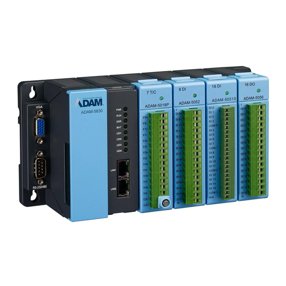
Overview ....................2 Figure 2.1 ADAM-5630E overview (the I/O module are optional, not included) ............... 2 LED Status Indicator ................. 2 Figure 2.2 ADAM-5630 series LED status indicator ....2 2.2.1 System Status Indicator ..............3 Chapter Wiring and Installation ......1... - Page 8 ADAM-5630_Series User Manual...
-
Page 9: Chapter 1 Introduction
Chapter Introduction... -
Page 10: Product Concepts And Positioning
4/8 I/O slots for sensing and control in energy and environment application, which plays an important role. To organize an ADAM-5630 Series Controller, you need to select I/O modules to interface the main unit with field devices or processes that you have previously deter- mined. -
Page 11: Hardware Specifications
Hardware Specifications 1.2.1 General Certification: CE, FCC Dimensions (W x D x H): – 4 slots: 231 x 75 x 110 mm – 8 slots: 355 x 75 x 110 mm Enclosure: ABS +PC Mounting: DIN-Rain, Wall-Mount ... -
Page 12: Safety Precautions
Operating Humidity: 20 ~ 95% (non-condensing) Shock Protection: IEC 60068-2-27 Vibration Protection: IEC 60068-2-64 (Random 1 Oct./min, 1hr/axis.) Safety Precautions The following messages inform how to make each connection. In most cases, you will simply need to connect a standard cable Warning! Always disconnect the power cord from your chassis whenever you are working on it. -
Page 13: Chassis Dimensions
Chassis Dimensions Figure 1.1 ADAM-5630E chassis dimensions Figure 1.2 ADAM-5630 chassis dimensions ADAM-5630_Series User Manual... - Page 14 ADAM-5630_Series User Manual...
- Page 15 Chapter Overview...
-
Page 16: Chapter 2 Overview
Overview The following figures show the indicators and connectors on ADAM-5630E. Figure 2.1 ADAM-5630E overview (the I/O module are optional, not included) LED Status Indicator Figure 2.2 ADAM-5630 series LED status indicator ADAM-5630_Series User Manual... -
Page 17: System Status Indicator
2.2.1 System Status Indicator Status Description Green Power is on Power is off Need to change Battery Normal Green Customers can define the Program- LED1~LED4 mable LED state according to the actual need. ADAM-5630_Series User Manual... - Page 18 ADAM-5630_Series User Manual...
-
Page 19: Chapter 3 Wiring And Installation
Chapter Wiring and Installation... -
Page 20: Wiring
Wiring 3.1.1 Power Supply Wiring ADAM-5630 supports power input ranging from 10 V to 30V Figure 3.1 Power Supply Wiring Table 3.1: DC Power Input Connector Pin Definition Function Screen Printing Function Description DC power input PIN DC power input PIN Power Input 3.1.2 Communication Ports... -
Page 21: Table 3.3: Usb Connector Pin Assignment
3.1.2.2 Terminal Connector 3.1.2.3 USB Connector Table 3.3: USB Connector Pin Assignment Signal Cable Color DATA- White DATA+ Green Black 3.1.2.4 LAN Connectors (LAN1~LAN2) Color Description Link Orange Lighting, Ethernet not connected Blinking, Ethernet data being transmit- Green ADAM-5630_Series User Manual... -
Page 22: Table 3.4: Vga Adaptor Cable Pin Assignments
Table 3.4: VGA Adaptor Cable Pin Assignments Assignment GREEN BLUE 3.1.2.6 Dial Switch Setting ADAM-5630 series have an 8-bit node ID. The detailed definition is as follows: Table 3.5: Node ID Setting Node ID 8-bit, support 0~255 devices. ADAM-5630_Series User Manual... -
Page 23: Jumper Setting
Jumper Setting 3.2.1 Jumper Setting The ADAM-5630 series has two types of jumper for user operation, as the below shown. Figure 3.2 The location of Jumper on the power board Table 3.6: Jumper Setting for COM1 Location Description RS-232 mode for COM1... -
Page 24: Table 3.7: Jumper Setting For Com2, 3
Table 3.7: Jumper Setting for COM2, 3 Location Description COM2 120 ohm TR in RS-485 mode COM2 300 ohm TR in RS-485 mode COM3 120 ohm TR in RS-485 mode COM3 300 ohm TR in RS-485 mode Figure 3.3 The location of Jumper on the main board ADAM-5630_Series User Manual... -
Page 25: Table 3.8: Jumper Setting For Com4
Table 3.8: Jumper Setting for COM4 Location Description RS-232 mode for COM4 RS-485 mode for COM4 COM4 120 ohm TR in RS-485 mode COM4 300 ohm TR in RS-485 mode ADAM-5630_Series User Manual... -
Page 26: Installation
Installation 3.3.1 System mounting ADAM-5630 series provides DIN-rail and wall mount, please refer the following examples: Figure 3.4 DIN-rail mounted Installation (8 slots as example) Figure 3.5 Wall mounted Installation (8 slots as example) ADAM-5630_Series User Manual... -
Page 27: Sd Card Installation
ADAM-5630 series are equipped with one Micro SD slots for data storage. Figure 3.6 SD Card Installation 3.3.3 Change RTC Battery ADAM-5630 series provide the external battery slot for user can easy change it. Figure 3.7 Battery replacement ADAM-5630_Series User Manual... - Page 28 No part of this publication may be reproduced in any form or by any means, electronic, photocopying, recording or otherwise, without prior written permis- sion of the publisher. All brand and product names are trademarks or registered trademarks of their respective companies. © Advantech Co., Ltd. 2018...
Need help?
Do you have a question about the ADAM-5630 Series and is the answer not in the manual?
Questions and answers