Table of Contents
Advertisement
Quick Links
Advertisement
Table of Contents

Subscribe to Our Youtube Channel
Related Manuals for Advantech UNO-348


Summary of Contents for Advantech UNO-348
- Page 1 User Manual UNO-348 電腦 Compact Embedded Edge Controller...
- Page 2 No part of this manual may be reproduced, copied, translated, or transmitted in any form or by any means without the prior written permission of Advantech Co., Ltd. The information provided in this manual is intended to be accurate and reliable.
- Page 3 UNO348ANN3A2504-T, UNO348ANN1AW2501-T, UNO348ANN3AW2501-T, UNO348ANN1A2601-T, UNO348ANN1A2604-T, UNO348ANN3A2601-T, UNO348ANN3A2604-T, UNO348ANN1AW2601-T, UNO348ANN3AW2601-T, UNO348ANN1A2701-T, UNO348ANN1A2704-T, UNO348ANN3A2701-T, UNO348ANN3A2704-T, UNO348ANN1AW2701-T, UNO348ANN3AW2701-T, UNO348ANN1A2505-T, UNO348ANN3A2502-T, UNO348ANN3A2505-T, UNO348ANN3AW2501-T, UNO348ANN3AW2502-T, UNO348ANN1A2602-T, UNO348ANN1A2605-T, UNO348ANN3A2602-T, UNO348ANN3A2605-T, UNO348ANN1AW2602-T, UNO348ANN3AW2602-T, UNO348ANN1A2702-T, UNO348ANN1A2705-T, UNO348ANN3A2702-T, UNO348ANN3A2705-T, UNO348ANN1AW2702-T, UNO348ANN3AW2702-T, UNO348ANN3A2503-T, UNO348ANN1A2603-T, UNO348ANN3A2603-T, UNO348ANN1A2703-T, UNO348ANN3A2703-T UNO-348 User Manual...
- Page 4 Product Warranty (2 years) Advantech warrants the original purchaser that each of its products will be free from defects in materials and workmanship for two years from the date of purchase. This warranty does not apply to any products that have been repaired or altered by persons other than repair personnel authorized by Advantech, or products that have been subject to misuse, abuse, accident, or improper installation.
- Page 5 甲類設備為其他符合甲類設備限制值之資訊技術設備,而非符合乙類資訊技術設備的 限制值;雖然不可限制此類設備之行銷,但使用場所必須被限制,不得進行居住的環 境中,且應於其機器本體及使用說明書中含有下列警語: Technical Support and Assistance Visit the Advantech website at www.advantech.com/support to obtain the latest product information. Contact your distributor, sales representative, or Advantech's customer service center for technical support if you need additional assistance. Please have the following information ready before calling: –...
- Page 6 This product is intended to be supplied by an UL certified power supply or dc source with mating connector, rated 10-36Vdc, 16A-4.44A minimum and Tma 50 degree. If you need further assistance, please contact Advantech for further information. Ensure that the voltage of the power source is correct before connecting the equipment to a power outlet.
- Page 7 If the equipment is used in a manner not specified by the Advantech, the protec- tion provided by the equipment may be impaired. The equipment contains no user-serviceable parts. Do not open, Return to man- ufacturer for servicing. Do not block air ventilation holes.
- Page 8 Attention: Surface chaude, ne pas toucher pour le dissipateur ther- mique supérieur. 安全指示 請仔細閱讀此安全操作說明。 請妥善保存此用戶手冊供日後參考。 用濕抹布清洗設備前,請確認拔除電源線。請勿使用液體或去污噴霧劑清洗設 備。 對於使用電源線的設備,設備周圍必須有容易接觸到的電源插座。 請勿在潮濕環境中試用設備。 請在安裝前確保設備放置在可靠的平面上,意外摔落可能會導致設備損壞。 設備機殼的開孔適用於空氣對,從而防止設備過熱。請勿覆蓋開孔。 當您連接設備到電源插座前,請確認電源插座的電壓符合要求。 請將電源線佈置在人們不易絆倒的位置,請勿在電源線上覆蓋任何雜物。 請注意設備上所有的警告標示。 如果長時間不使用設備,請拔除與電源插座的連結,避免設備被超標的電壓波動 損壞。 請勿讓任何液體流入通風口,以免引起火灾或短路。 請勿自行打開設備。為了確保您的安全,請透過經認證的工程師來打開設備。 如遇下列情况,請由專業人員維修: 電源線或插頭損壞; 設備內部有液體流入; 設備曾暴露在過度潮濕環境中使用; UNO-348 User Manual viii...
- Page 9 設備無法正常工作,或您無法透過用戶手冊來正常工作; 設備摔落或損壞; 設備有明顯外觀損; 請勿將設備放置在超出建議溫度範圍的環境,即不要低於 -40° C (-40° F)或 高於 85° C (185° F),否則可能會造成設備損壞。 注意:若電池更換不正確,將有爆炸危險。因此,只可以使用製造商推薦的同一 種或者同等型號的電池進行替換。請按照製造商的指示處理舊電池。 根據 IEC 704‐1:1982 規定,操作員所在位置音量不可高於 70 分貝。 限制區域:請勿將設備安裝於限制區域使用。 免責聲明:請安全訓示符合 IEC 704‐1 要求。研華公司對其內容之準確性不承 擔任何法律責任。 UNO-348 User Manual...
- Page 10 UNO-348 User Manual...
-
Page 11: Table Of Contents
Chapter Hardware Functionality.......7 Introduction ....................8 Figure 2.1 Diagram of Connector Locations on UNO-348 of Moth- erBoard (Top Side) ............. 8 Figure 2.2 Diagram of Key Components Location on UNO-348 of MotherBoard (Bottom Side)........8 Table 2.1: Key Components, Connectors on Board ....9 Figure 2.3 Diagram of Key Components Location on UNO-348-... - Page 12 Figure 2.15Illustration of antenna installed......... 21 Chapter Initial Setup........23 Chassis Grounding ................. 24 Figure 3.1 Chassis Grounding Connection Diagram of UNO-348- AXX1A (1 Slot) ............24 Figure 3.2 Chassis Grounding Connection Diagram of UNO-348- AXX3A (3 Slot) ............24 Connecting Power................... 25 Storage Installation (Optional) ..............
- Page 13 Table A.8: mPCIe Connector Pin Assignments ......49 COM Port RS232/422/485 Settings ............50 TPM 2.0 BIOS Setting................54 CPU Turbo Mode BIOS Setting ............. 55 xiii UNO-348 User Manual...
- Page 14 UNO-348 User Manual...
-
Page 15: Chapter 1 Overview
Chapter Overview This chapter overviews specifica- tions for UNO-348. Introduction Safety Precautions Accessories Hardware Specifications Dimensions... -
Page 16: Introduction
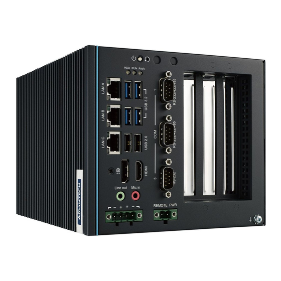
UNO-348 is a high-performance, fanless, embedded edge controller supports 10th gen. Intel® Core i CPU. Despite its compact size, UNO-348 offers multiple I/O includ- ing 4 x USB 3.2, 2 x USB 2.0, 3 x GigaLAN, 2 x RS-232/422/485, and 1 x RS-232 ports, as well as 1 x Line-out, 1 x Mic-in, 1 x DisplayPort, and 1 x HDMI interfaces. -
Page 17: Packing List
Simplified Chinese manual China RoHs sheet Warranty card For UNO-348-ANN1A/ UNO-348-ANN3A, there’s an additional accessory bag for post-assemble as below: 1 x Grease for CPU 17 x M3x6L Screw for Chassis 4 x M3x4L Screw for Mother Board ... -
Page 18: Hardware Specifications
Hardware Specifications 1.5.1 General UNO-348 (1 slot): 200 x 140 x 120 mm (7.8 x 5.5 x 4.7 in) Dimensions (W x D x H) UNO-348 (3 slot): 200 x 140 x 160 mm (7.8 x 5.5 x 6.3 in) UNO-348 (1 slot): 3.5 kg (7.7 lbs) -
Page 19: Environment
95% RH @ 40 °C/104 °F, non-condensing Shock Protection Operating, IEC 60068-2-27, 50G, half sine, 11ms Operating, IEC 60068-2-64, 4Grms, random, 5 ~500Hz, 1hr/ Vibration Protection axis (SSD) Ingress Protection IP20 1.5.5 Certification CE, FCC, CB, UL, CCC, BSMI, CAN ICES-003(A)/NMB- Certification 003(A) UNO-348 User Manual... -
Page 20: Dimensions
1.6.1 UNO-348-AXX1A Dimensions 200 x 140 x 120 mm (7.8 x 5.5 x 4.7 in) (W x D x H) Figure 1.1 UNO-348 (1 Slot) Dimensions 1.6.2 UNO-348-AXX3A Dimensions 200 x 140 x 160 mm (7.8 x 5.5 x 6.3 in) (W x D x H) Figure 1.2 UNO-348 (3 slot) Dimensions... -
Page 21: Chapter 2 Hardware Functionality
Chapter Hardware Functionality This chapter details setup instruc- tions for UNO-348’s hardware functions. It includes connecting peripherals and indicators. Introduction External I/O Connector Internal I/O Connector LED Indicators Reset Buttons Antenna Hole... -
Page 22: Introduction
Introduction The following diagram demonstrates the location of UNO-348’s motherboard’s key components and internal/external connectors. Figure 2.1 Diagram of Connector Locations on UNO-348 of MotherBoard (Top Side) Figure 2.2 Diagram of Key Components Location on UNO-348 of MotherBoard (Bottom Side) - Page 23 GPIO1 GPIO Connector Internal COM1 Serial Port Connector COM2 Serial Port Connector CN10 ATX/AT Header JCMOS1 CMOS Header BAT1 Battery Connector Figure 2.3 Diagram of Key Components Location on UNO-348-AXX1A (1 Slot) of Backplane Board (TOP Side) UNO-348 User Manual...
- Page 24 Figure 2.4 Diagram of Key Components Location on UNO-348-AXX1A (1 Slot) of Backplane Board (IO 1-slot Bottom Side) Table 2.2: Key components, Connectors on IO 1-slot Board Category Label Function Power Input connector External Remote connector iDoor Power connector SYSFAN1...
- Page 25 Figure 2.5 Diagram of Key Components Location on UNO-348-AXX3A (3 Slot) of Backplane Board (TOP Side) Figure 2.6 Diagram of Key Components Location on UNO-348-AXX3A (3 Slot) of Backplane Board (Bottom Side) UNO-348 User Manual...
- Page 26 Figure 2.7 Diagram of Key Components Location on UNO-348-AXX3AW (3 Slot) of Backplane Board (TOP Side) Figure 2.8 Diagram of Key Components Location on UNO-348-AXX3AW (3 Slot) of Backplane Board (Bottom Side) UNO-348 User Manual...
-
Page 27: External I/O Connector
2.2.1 Power Connector UNO-348 comes with a terminal block connector that carries 10 - 36 VDC external power input, and features reversed wiring protection. Therefore, the system will not accrue damage from reversed polarity of ground lines and power lines. -
Page 28: Display Connector
2.2.4 Display Connector The UNO-348 provides 1x DP 1.4 connector for a high resolution interface up to 4096 x 2306 @ 60Hz and provide 1 x HDMI 1.4 connector for a high resolution interface up to 4096 x 2160 @ 30Hz. It also supports DP++ that can be compatible with passive adapter. -
Page 29: Gpio
PIN9 GPIO3 GPIO4 GPIO5 GPIO6 GPIO7 2.2.7 Audio UNO-348 has two audio ports with phone jack connectors, one Line-Out and one Mic-In. 2.2.8 Remote Power Control UNO-348 provide two pins for remotely control power on/off or reset. UNO-348 User Manual... -
Page 30: Internal I/O Connectors And Switches
Internal I/O Connectors and Switches The following figure demonstrates the locations of internal connectors and switches on the UNO-348’s motherboard. Figure 2.12 Locations Internal I/O Connectors/Switches for UNO-348 Table 2.4: Internal Connectors and Jumper Switches Label Function M.2 B key for 2280 (support 3042/3052 by bracket) - Page 31 Table 2.5: Internal Connectors and Jumper Switches Label Function iDoor Power connector SYSFAN1 External system FAN power connector (reserve) PCIe x16 slot SATA Connector SATA Connector MINIPCIE2_MSATA1 miniPCIe connector PSON1 Remote jumper setting connector UNO-348 User Manual...
- Page 32 External system FAN power connector (reserve) PCIe x16 slot SATA Connector SATA Connector MINIPCIE2_MSATA1 miniPCIe connector PSON1 Remote jumper setting connector PCI1 PCI slot connector PCI2 PCI slot connector (For UNO-348-AXX3A) Note! *This power is from DC Power inputs UNO-348 User Manual...
-
Page 33: Connector
There’s one sockets for full size PCI Express mini cards, labeled “MINIPCIE2_MSA- TA1” on the board. It supports iDoor module for diversified applications such as isolated COM port, Pro- fibus, WLAN GPRS, LTE, and MRAM. Users can install the iDoor easily with optional extension kit. UNO-348 User Manual... -
Page 34: Pcie X16 Connector
There’s one sockets for full size PCI Express cards, labeled “CN6” on the I/O board. (PCIe card support 75W Max.) 2.3.4 PCI Connector For the 3 slot version UNO-348 (UNO-348-AXX3A), there are two sockets for half length PCI cards, labeled “PCI1 and PCI2" on the I/O board. (PCI card support 25W Max.) Others Figure 2.13 LED Indicators, Reset Buttons, and Antenna Hole of UNO-348-... -
Page 35: Reset Buttons
This product offers two antenna mounting holes covered by pre-cut holes for users to install an antenna kit for LTE or wireless functions. Note! Please be aware of the Maximum OD value of the Antenna Hole when selecting antenna Figure 2.15 Illustration of antenna installed UNO-348 User Manual... - Page 36 UNO-348 User Manual...
-
Page 37: Initial Setup
Chapter Initial Setup This chapter explains how to Ini- tialize the UNO-348. Chassis Grounding Connecting Power Storage Installation (Optional) Wireless Module Installation (Optional) Expansion Module Installation (Optional) Remote Power/On & Reset Set- ting BIOS Setting... -
Page 38: Chassis Grounding
Chassis Grounding The UNO-348 provides good EMI protection and a stable grounding base. There is an easy-to-connect chassis grounding point. Figure 3.1 Chassis Grounding Connection Diagram of UNO-348-AXX1A (1 Slot) Figure 3.2 Chassis Grounding Connection Diagram of UNO-348-AXX3A (3 Slot) Use the Grounding cable (16 AWG) from the accessory bag to connect the chassis ground with the Earth ground. -
Page 39: Connecting Power
This product is intended to be supplied by an approved power adapter or DC power source. This adapter is rated at 10 - 36Vdc, 16A~4.44A and has a Tmax of 50 °C (158 °F). If you need further assistance or information, please contact Advantech. Follow the following instructions: Insert the positive and negative wires into the V+ and V- contacts on the termi- nal block connector. -
Page 40: Storage Installation (Optional)
Storage Installation (Optional) UNO-348 supports the installation of one 2.5” HDD/ SDD and one M.2 2280 SSD. The installation is demonstrated in the following steps. 3.3.1 Installing a 2.5” HDD/SSD Remove 9 x screws(M3x4L) from UNO’s top cover. Remove 2 screws (M3x4L) to take out the SSD Bracket. - Page 41 Fix the 2.5” SSD to SSD Bracket with the 8 x (M3x4L) screws for each SSD pro- vided in accessory bag. Fix back the SSD bracket onto to the UNO-348 product with the screw from step UNO-348 User Manual...
-
Page 42: Installing M.2 2280 Module
3.3.2 Installing M.2 2280 Module Remove 9 x screws(M3x4L) from the top cover of UNO. Insert the M.2 2280 card on the location: “CN6”. Secure it with 1pc (M3x4L) screw provided in accessory bag. UNO-348 User Manual... -
Page 43: Installing M.2 3042/2242 Module
Screw 1 x M3x4L screw on the standoff (POST1) but not tighten it. Place M.2 adapter bracket to align with the screw then tighten it. * M3x4L screw and M.2 adapter bracket is provided in accessory bag. The M.2 adapter bracket is marked "A" on it. UNO-348 User Manual... -
Page 44: Installing M.2 3052 Module
Insert the M.2 3042 or 2242 card on the location: “CN6” and secure it with the M.2 Bracket with 1 x M3x4L screws provided in accessory bag. 3.3.4 Installing M.2 3052 Module Remove 9 x screws(M3x4L) from the top cover of UNO. UNO-348 User Manual... - Page 45 * M3x4L screw and M.2 adapter bracket is provided in accessory bag. The M.2 adapter bracket is marked "B" on it. Insert the M.2 3052 card on the location: “CN6” and secure it with the M.2 Bracket with 1 x M3x4L screws provided in accessory bag. UNO-348 User Manual...
-
Page 46: Installing Gpio
3.3.5 Installing GPIO Remove 9 x (M3x4L)screws from the top cover of UNO. Remove RS232 DB9 cable with 2 Hex Head screw UNO-348 User Manual... - Page 47 Fix the GPIO cable with 2 Hex Head screw *GPIO Cable is optional, the recommended PN is 1700030635-01. Cable connect the board on the location: “GPIO1”. UNO-348 User Manual...
-
Page 48: Installing Idoor
The PN is PCM-28P1BK-AE Remove 9 x screws(M3x4L) from the top cover of UNO. Remove 3 x screws(M3x4L) to take off the front panel of UNO-348 and remove 1 x screw (M3x4L) to take off the dummy PCIe/PCI bracket. - Page 49 Insert the mPCIe card of iDoor module to the location: “MINIPCIE2_MSATA1” and secure it with the 1 (M2x4L)screw provided in accessory bag. Fix the front cover back with the screw from step 2. UNO-348 User Manual...
- Page 50 (IDoor Module) Fix the IDOOR Module and the “iDoor PCIe I/O plate” with 2pcs (M3x5L)screw provide in accessory bag. Insert the Module to the UNO-348 product and fix the iDoor Module with 1pc (M3x4L) screw from step 2. UNO-348 User Manual...
-
Page 51: Wall Mount And Stand Mount Installation
Wall Mount and Stand Mount Installation 3.4.1 Wall mount Remove 4pcs M4x5 screws. Screw the wall mount kit on UNO-348 with the 4pcs screws from step1. UNO-348 User Manual... - Page 52 Mount UNO-348 on wall by 4 (M4x5L) screws. UNO-348 User Manual...
-
Page 53: Stand Mount
3.4.2 Stand mount Remove 4pcs M4x5 screws. Screw the wall mount kit on UNO-348 with the 4pcs screws from step1. UNO-348 User Manual... - Page 54 Mount UNO-348 on wall by 4 (M4x5L) screws UNO-348 User Manual...
- Page 55 UNO-348 User Manual...
-
Page 56: Remote Power/Reset Setting
Instruction (1-2) (Default) Remote power function (2-3) Remote reset function UNO-348 supports remote power/ reset function, and it can be adjusted via CN11 on the I/O board. The default setting is for remote power function.(for UNO-348- ANN3AW) CN11 Description Instruction... -
Page 57: Appendix A System Settings/Pin Assignment
Appendix System Settings/Pin Assignment... -
Page 58: Power Connector (Bp_Cn1)
1000BASE-T: In MDI and in MDI-X configuration, MDI2- MDI[2]+/- corresponds to BI_DC+/- and MDI[3]+/ - corresponds to BI_DD+/-. MDI3+ 100BASE-TX: Unused. MDI3- 10BASE-T: Unused. Left LED Right LED 10 Link 100 Link 1000 Link Active Orange Green Green UNO-348 User Manual... -
Page 59: Usb Connector (Lan1_Usb3C1, Lan2_Usb3C2, Lan3_Usb3C3)
USB 3.0 Connector Table A.4: USB 3.0 Connector Pin Assignments Signal Name Description VBUS Power USB2.0 differential pair Ground for power return StdA_SSRX- SuperSpeed receiver differential pair StdA_SSRX+ GND_DRIAN Ground for signal return StdA_SSTX- SuperSpeed transmitter differential pair StdA_SSTX+ UNO-348 User Manual... -
Page 60: Display Connector (Cn1), Hdmi Connector (Cn1)
Signal Name ML_Lane 0 (p) ML_Lane 0 (n) ML_Lane 1 (p) ML_Lane 1 (n) ML_Lane 2 (p) ML_Lane2 (2) ML_Lane 3 (p) ML_Lane 3 (n) CONFIG1 CONFIG2 AUX CH (p) AUX CH (n) Hot Plug Return DP_PWR UNO-348 User Manual... - Page 61 Table A.6: HDMI Adapter cable Pin Assignments Signal Name TMDS Data2+ TMDS Data2 Shield TMDS Data2- TMDS Data1+ TMDS Data1 Shield TMDS Data1- TMDS Data0+ TMDS Data0 Shield TMDS Data0- TMDS Clock+ TMDS Clock Shield TMDS Clock- DDC/CEC Ground Hot Plug Detect UNO-348 User Manual...
-
Page 62: Connector (Cn6)
Mechanical notch B Mechanical notch B Mechanical notch B Mechanical notch B Mechanical notch B Mechanical notch B WAKE_ON_WAN# M2_LTE_W2_DISABLE_N USB_Z_SSRX1- M2_SIM1_RESET USB_Z_SSRX1+ M2_SIM1_CLK M2_SIM1_DATA USB_C_SSTX1- M2_SIM1_PWR USB_C_SSTX1+ M2_SIM2_DET SATA1_RX+ SATA1_RX- SATA1_C_TX- SATA1_C_TX+ M2_SIM1_DET LTE_RST#_P67 +V3.3_M2 +V3.3_M2 UNO-348 User Manual... -
Page 63: Mpcie Connector (Minipcie2_Msata1)
Table A.7: M.2 B Key Connector Pin Assignments +V3.3_M2 mPCIe Connector (MINIPCIE2_MSATA1) Table A.8: mPCIe Connector Pin Assignments Signal Name Signal Name PCIE_WAKE#_3.3 +V3.3_MINI +V1.5 +V3.3 CLK_PCIE_mPCIe1- CLK_PCIE_mPCIe1+ WIFI_DISABLE# MINI_PLTRST# PCIE_mPCIe_RX4- +V3.3_MINI PCIE_mPCIe_RX4+ +V1.5 PCIE_TX2-_Z PCIE_TX2+Z USB_Z_P0- USB_Z_P0+ +V3.3_MINI +V3.3_MINI MPCIE_PWRSEL +V1.5 +V3.3_MINI UNO-348 User Manual... - Page 64 COM Port RS232/422/485 Settings Power on the UNO-348 system and press “Delete” to enter the BIOS configura- tion menu. On the “Advanced” tab, select the “NCT6126D Super IO” item. Select the "Serial Port 1/Port 2" item. UNO-348 User Manual...
- Page 65 Select the “Device Mode” item.to choose Com port mode (RS-232/RS-422/RS485), default RS-232 mode. Select the “Serial Port 3” item. UNO-348 User Manual...
- Page 66 Serial Port 3 only support RS-232 mode. Select the “Serial Port 4” item. UNO-348 User Manual...
- Page 67 Serial Port 4 for iBMC debug port (default is disable). UNO-348 User Manual...
- Page 68 TPM 2.0 BIOS Setting The UNO-348 systems support TPM 2.0 functionality. This can be enabled or dis- abled in the BIOS menu by following the instructions provided below: Power on the UNO-348 system and press “Delete” to enter the BIOS configura- tion menu.
- Page 69 CPU Turbo Mode BIOS Setting The UNO-348 systems support CPU Turbo mode. This can be enabled or disabled in the BIOS menu by following the instructions: Power on the UNO-348 system and press “Delete” to enter the BIOS configura- tion menu.
- Page 70 Then select the “CPU Power Management” item. Choose “enable/disable” to enable or disable the CPU Turbo mode (The default setting is to enable this function). UNO-348 User Manual...
- Page 71 UNO-348 User Manual...
- Page 72 No part of this publication may be reproduced in any form or by any means, electronic, photocopying, recording or otherwise, without prior written permis- sion of the publisher. All brand and product names are trademarks or registered trademarks of their respective companies. © Advantech Co., Ltd. 2022...
Need help?
Do you have a question about the UNO-348 and is the answer not in the manual?
Questions and answers