
Related Manuals for Advantech UNO-127


Summary of Contents for Advantech UNO-127
- Page 1 User Manual UNO-127 Intel® Atom™ Elkhart Lake x6413E Compact Fanless Edge Controller...
- Page 2 No part of this manual may be reproduced, copied, translated, or transmitted in any form or by any means without the prior written permission of Advantech Co., Ltd. The information provided in this manual is intended to be accurate and reliable.
- Page 3 UNO127E23B2210-T, UNO127E23B2211-T, UNO127E23B2212-T UNO127E23B2301-T, UNO127E23B2302T, UNO127E23B2303-T UNO127E23B2304-T, UNO127E23B2305-T, UNO127E23B2306-T UNO127E23B2307-T, UNO127E23B2308-T, UNO127E23B2309-T UNO127E23B2310-T, UNO127E23B2311-T, UNO127E23B2312-T UNO127E23B2401-T, UNO127E23B2402-T, UNO127E23B2403-T UNO127E23B2404-T, UNO127E23B2405-T, UNO127E23B2406-T UNO127E23B2407-T, UNO127E23B2408-T, UNO127E23B2409-T UNO127E23B2410-T, UNO127E23B2411-T, UNO127E23B2412-T UNO127E23B2501-T, UNO127E23B2502-T, UNO127E23B2503-T UNO127E23B2504-T, UNO127E23B2505-T, UNO127E23B2506-T UNO127E23B2507-T, UNO127E23B2508-T, UNO127E23B2509-T UNO127E23B2510-T, UNO127E23B2511-T, UNO127E23B2512-T UNO-127 User Manual...
- Page 4 Product Warranty (2 years) Advantech warrants the original purchaser that each of its products will be free from defects in materials and workmanship for two years from the date of purchase. This warranty does not apply to any products that have been repaired or altered by persons other than repair personnel authorized by Advantech, or products that have been subject to misuse, abuse, accident, or improper installation.
- Page 5 限制值;雖然不可限制此類設備之行銷,但使用場所必須被限制,不得進行居住的環 境中,且應於其機器本體及使用說明書中含有下列警語 : Technical Support and Assistance Visit the Advantech website at www.advantech.com/support to obtain the latest product information. Contact your distributor, sales representative, or Advantech's customer service center for technical support if you need additional assistance. Please have the following information ready before calling: –...
- Page 6 This equipment is not suitable for use in locations where children are likely to be present. If the equipment is used in a manner not specified by the Advantech, the protec- tion provided by the equipment may be impaired. UNO-127 User Manual...
- Page 7 Do not block air ventilation holes. This is open type equipment and should be installed in a suitable enclosure. DISCLAIMER: These instructions are provided according to IEC 704-1 standards. Advantech disclaims all responsibility for the accuracy of any statements contained herein. Consignes de sécurité...
- Page 8 設備無法正常工作,或您無法透過用戶手冊來正常工作; 設備摔落或損壞; 設備有明顯外觀損; 15. 請勿將設備放置在超出建議溫度範圍的環境,即不要低於 -20°C (-4°F)或高 於 50°C (122°F) ,否則可能會造成設備損壞。 16. 注意:若電池更換不正確,將有爆炸危險。因此,只可以使用製造商推薦的同一 種或者同等型號的電池進行替換。請按照製造商的指示處理舊電池。 17. 根據 IEC 704‐1:1982 規定,操作員所在位置音量不可高於 70 分貝。 18. 限制區域:請勿將設備安裝於限制區域使用。 19. 免責聲明:請安全訓示符合 IEC 704‐1 要求。研華公司對其內容之準確性不承 擔任何法律責任。 20. 消费者若使用电源适配器供电,则应购买配套使用获得 CCC 认证并满足标准要求 的电源适配器。 UNO-127 User Manual viii...
-
Page 9: Table Of Contents
Extension kit) ............5 Chapter Hardware Functionality.......7 Introduction ....................8 Figure 2.1 Diagram of Connector Locations on UNO-127 (Top Side) ................8 Figure 2.2 Diagram of Key Components Location on UNO-127 (Bottom Side).............. 8 Table 2.1: Key components, Connectors on Board..... 9 External I/O Connector................ - Page 10 3.5.1 4 x COM & 1 x LAN extension kit (UNO-127-RS1EA)....18 BIOS Setting ................... 20 Appendix A System Settings & Pin Defs ..... 21 Power Connector (DCIN1) ..............22 Table A.1: Power connector pin assignments ......22 LAN: Ethernet Connector (LAN1) ............22 Table A.2: Ethernet Connector Pin Assignments ......
-
Page 11: Chapter 1 Overview
Chapter Overview This chapter provides an overview of UNO-127 specifications. Sections include: Introduction Safety Precautions Accessories Hardware Specifications Dimensions... -
Page 12: Introduction
UNO-127 is equipped with an Intel® Atom® 6413E processor, 4 or 8 GB DDR4 RAM, and 64G eMMC storage, as well as 2 x LAN, 2 x USB and 1 x HDMI. It also supports 1 x full-size mini PCIe for convenient expansion to satisfy diverse industrial applica- tions. -
Page 13: Packing List
Packing List Please refer below for the packing list: UNO-127 (with din-rail mount) 1 x 2 PIN Plug-in block for Power 1 x Earth-Ground cable Quick Start Guide Warranty card If anything is missing or damaged, contact your distributor or sales representative immediately. -
Page 14: Environment
*Note: Operating Temperature to be -20 ~ 50 °C (-4 ~ 122 °F) without airflow. 1.4.5 Certifications Certification CE, FCC, CB, UL 61010-2-201, CCC, BSMI 1.4.6 Extension Kit (Optional) UNO-127 features a modularized design. Advantech offers an optional 2nd extension kit. UNO-127-RS1EA Extension unit Part number UNO-127-RS1EA Description 2nd stack extension kit to support 1 x M.2 B key Interface... -
Page 15: Dimensions
1.4.7 Dimensions 33.5 x 70 x 100 mm (W x D x H mm) Figure 1.1 UNO-127 Dimensions Figure 1.2 UNO-127 Dimensions (With UNO-127-RS1EA Optional Extension kit) UNO-127 User Manual... - Page 16 UNO-127 User Manual...
-
Page 17: Chapter 2 Hardware Functionality
Chapter Hardware Functionality This chapter shows how to setup the UNO-127’s hardware func- tions, including connecting peripherals, setting switches and indicators. Sections include: Introduction External I/O Connector Internal I/O Connector LED Indicators Reset Buttons Antenna Hole... -
Page 18: Introduction
The following diagram demonstrates the location of UNO-127's motherboard's key components and internal/external connectors. DIMM3 DIMM1 CPU1 Figure 2.1 Diagram of Connector Locations on UNO-127 (Top Side) DIMM3 DIMM1 CPU1 Figure 2.2 Diagram of Key Components Location on UNO-127 (Bottom Side) UNO-127 User Manual... -
Page 19: External I/O Connector
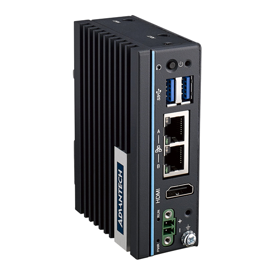
Riser Connector MINI1 MiniPCIe Connector DIMM1 Memory Slot Internal DIMM2 Memory Slot DIMM3 Memory Slot DIMM4 Memory Slot External I/O Connector 2.2.1 UNO-127 Base Unit Figure 2.3 Front Panel of UNO-127 Figure 2.4 Top View of UNO-127 UNO-127 User Manual... -
Page 20: Power Connector
2.2.4 USB Connector UNO-127 features 2 x USB ports that comply with USB EHCI, 3 for Rev. 3.2 specifi- cations. The USB connectors support plug-and-play and hot-swap- ping functionality for external devices. Additionally, this can be enabled/disabled in the BIOS menu. -
Page 21: Internal I/O Connectors And Switches
RS232 RS232 RS422 RS422 RS485 RS485 Internal I/O Connectors and Switches The following figure demonstrates the locations of internal connectors and switches on the UNO-127’s motherboard. BAT1 PSON1 LAN1 USB1 PWR1 DCIN1 Figure 2.5 Internal I/O Connectors/Switches Table 2.3: Internal Connectors and Jumper Switches... -
Page 22: Connector
PWR (Power): Green indicates "normal" and orange indicates "standby". RUN (Programmable): Users can configure the LED indicator's behavior through GPIO signal controls. Green indicates under programming. 2.4.2 Reset Buttons Press the "Reset" button to initiate a hardware reset. UNO-127 User Manual... -
Page 23: Chapter 3 Initial Setup
Chapter Initial Setup This chapter introduces how to initialize the UNO-127. Sections include: Chassis Grounding Connecting Power Wireless Module Installation (Optional) Extension Module Installation (Optional) Remote Power/On & Reset Set- ting BIOS Settings... -
Page 24: Chassis Grounding
Chassis Grounding The UNO-127 provides good EMI protection and a stable grounding base. There is an easy-to-connect chassis grounding point. Figure 3.1 Chassis Grounding Connection Diagram Earth terminal shall be used 16 AWG minimum size with green and yellow conductor to connector to earth. -
Page 25: Storage Installation (Optional)
Storage Installation (Optional) UNO-127 supports the installation of one mPCIe mSATA SSD. The installation is 3.3.1 Installing mPCIE Remove the five screws from UNO’s back cover. Insert the mSATA storage in the location “CN15”. UNO-127 User Manual... - Page 26 Secure it with the screws from accessories box.. Install the 5 screws onto the back cover. (Note. The sign “II” always faces to the front IO). UNO-127 User Manual...
-
Page 27: Mounting Type: Din-Rail
Mounting type: Din-rail UNO-127 supports WiFi modules. Follow the steps below for installation: Remove five screws from the back cover of UNO. Remove the plug of antenna pre-cut hole(s) on the top panel for antenna instal- lation Install the SMA connector of Antenna cable onto the Antenna hole Connect the MHF of Antenna cable with the module Fix the washers and screw nut. -
Page 28: Extension Kit Installation (Optional)
The accessory list for iDoor extension kit (PN: UNO-127-RS1EA) 3 x M2.5x4L screws for back cover installation 2 x plugs for hollow holes installation Follow the steps below for extension kit Installation: Remove M2.5 x4L x 5 screws from the back cover of UNO-127. UNO-127 User Manual... - Page 29 M3 x4L x 3 screws #2 for attaching the base unit and extension kit. Re-attached 3 screws back into the position labeled “II”, and installed the plugs in the hollow holes. (Note. Sign “II” always faces to the front IO) UNO-127 User Manual...
-
Page 30: Bios Setting
"Del" key during the Power On Self Test (POST) process to enter the BIOS setup screen, otherwise the system will continue the POST process. (Please refer to User Manual- Appendix A.10/ A.11 for more settings) UNO-127 User Manual... -
Page 31: Appendix A System Settings & Pin Defs
Appendix System Settings & Pin Defs... -
Page 32: Power Connector (Dcin1)
MDI[1]+/- is used for the transmit pair. MDI2+ In BASE-T: Media Dependent Interface[3:2]: 1000BASE-T: In MDI and in MDI-X configuration, MDI2- MDI[2]+/- corresponds to BI_DC+/- and MDI[3]+/- corre- sponds to BI_DD+/-. MDI3+ 100BASE-TX: Unused. 10BASE-T: Unused. MDI3- UNO-127 User Manual... -
Page 33: Usb Connector (Usb1)
Table A.3: USB 3.0 Connector Pin Assignments Signal Name Description VBUS Power USB 2.0 differential pair Ground for power return StdA_SSRX- SuperSpeed receiver differential pair StdA_SSRX+ GND_DRIAN Ground for signal return StdA_SSTX- SuperSpeed transmitter differential pair StdA_SSTX+ UNO-127 User Manual... -
Page 34: Hdmi Connector (Cn1)
Signal Name Signal Name M2_SATA1_DET +V3.3_M2 +V3.3_M2 M2_LTE_PWR_OFF# M2_LTE_USB_DP M2_LTE_W1_DISABLE_N M2_LTE_USB_DN +V3.3_M2 Mechanical notch B Mechanical notch B Mechanical notch B Mechanical notch B Mechanical notch B Mechanical notch B Mechanical notch B Mechanical notch B WAKE_ON_WAN# M2_LTE_W2_DISABLE_N UNO-127 User Manual... - Page 35 Table A.5: M.2 B Key Connector Pin Assignments USB_Z_SSRX1- M2_SIM1_RESET USB_Z_SSRX1+ M2_SIM1_CLK M2_SIM1_DATA USB_C_SSTX1- M2_SIM1_PWR USB_C_SSTX1+ M2_SIM2_DET SATA1_RX+ SATA1_RX- SATA1_C_TX- SATA1_C_TX+ M2_SIM1_DET LTE_RST#_P67 +V3.3_M2 +V3.3_M2 +V3.3_M2 UNO-127 User Manual...
-
Page 36: Mpcie Connector (Mini1)
Connector (MINI1) Table A.6: mPCIe Connector Pin Assignments Signal Name Signal Name PCIE_WAKE#_3.3 +V3.3_MINI +V1.5 +V3.3 CLK_PCIE_mPCIe1- CLK_PCIE_mPCIe1+ WIFI_DISABLE# MINI_PLTRST# PCIE_mPCIe_RX4- +V3.3_MINI PCIE_mPCIe_RX4+ +V1.5 PCIE_TX2-_Z PCIE_TX2+Z USB_Z_P0- USB_Z_P0+ +V3.3_MINI +V3.3_MINI MPCIE_PWRSEL +V1.5 +V3.3_MINI UNO-127 User Manual... -
Page 37: Com Port Rs232/422/485 Settings
COM1/COM2 RS232/422/485 Settings SW1 Default Description This switch is used to select RS232/422/485 mode settings Default RS232 mode A.7.2 COM3/COM4 RS232/422/485 Setting SW2 Default Description This switch is used to select RS232/422/485 mode settings Default RS232 mode UNO-127 User Manual... - Page 38 RS485 Mode Bit 1,3,6,7,8,9,10 OFF Bit 1,2,4,5 ON RS422 Mode Bit 3,6,7,8,9,10 OFF Bit 6 ON RS232 Mode Bit 1,2,3,4,5,7,8,9,10 OFF Bit 7,9,10 ON COM2 RS485 Mode Bit 1,2,3,4,5,7,8 OFF Bit 6,7,9,10 ON RS422 Mode Bit 1,2,3,4,5,8 OFF UNO-127 User Manual...
- Page 39 RS485 Mode Bit 1,3,6,7,8,9,10 OFF Bit 1,2,4,5 ON RS422 Mode Bit 3,6,7,8,9,10 OFF Bit 6 ON RS232 Mode Bit 1,2,3,4,5,7,8,9,10 OFF Bit 7,9,10 ON COM4 RS485 Mode Bit 1,2,3,4,5,7,8 OFF Bit 6,7,9,10 ON RS422 Mode Bit 1,2,3,4,5,8 OFF UNO-127 User Manual...
-
Page 40: Com Port Rs422/485 Termination Resistor Setting
PSON1 using jumper for setting AT/ATX mode. The default setting is AT mode. See the follow- ing table for jumper installation for mode. PIN 1 2 Default Description Instruction PSON1 ATX Mode Closed 2-3 AT Mode (Default) Closed 1-2 UNO-127 User Manual... -
Page 41: Riser Connector
Riser Connector Signal Name Signal Name DCIN DCIN DCIN DCIN SMB_CLK SMB_DAT USB+ USB- PCIeX4_EN CLK+ CLK- RX0+ RX0- TX0+ TX0- SLP_S3 RX1+ RX1- TX1+ TX1- RX2+ RX2- TX2+ TX2- RX3+ RX3- TX3+ TX3- PLTRST SATA0_DET SATA1_DET UNO-127 User Manual... -
Page 42: Tpm 2.0 Bios Setting
A.10 TPM 2.0 BIOS Setting The UNO-127 systems support TPM 2.0 functionality. This can be enabled or dis- abled in the BIOS menu by following the instructions provided below: Power on the UNO-127 system and press “Delete” to enter the BIOS configura- tion menu. -
Page 43: Cpu Turbo Mode Bios Setting
A.11 CPU Turbo Mode BIOS Setting The UNO-127 systems support CPU Turbo mode. This can be enabled or disabled in the BIOS menu by following the instructions: Power on the UNO-127 system and press “Delete” to enter the BIOS configura- tion menu. - Page 44 No part of this publication may be reproduced in any form or by any means, electronic, photocopying, recording or otherwise, without prior written permis- sion of the publisher. All brand and product names are trademarks or registered trademarks of their respective companies. © Advantech Co., Ltd. 2022...
Need help?
Do you have a question about the UNO-127 and is the answer not in the manual?
Questions and answers