
Related Manuals for Advantech IPC-623 Series


Summary of Contents for Advantech IPC-623 Series
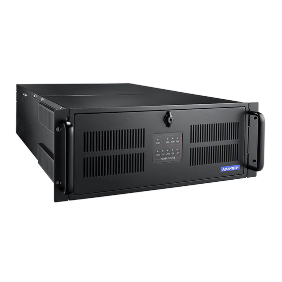
- Page 1 IPC-623 Series 4U-High Multi-segment Rackmount Industrial PC Chassis User’s Manual...
- Page 2 Copyright Notice This documentation and the software included with this product is copyrighted, January 2005, by Advantech Co., Ltd. All rights are reserved. Advantech Co., Ltd. reserves the right to make improvements in the products described in this manual at any time without notice.
- Page 3 Advantech equipment is destined for the laboratory or the factory floor, you can be assured that your product will provide the reliability and ease of operation for which the name Advantech has come to be known. Your satisfaction is our primary concern. Here is a guide to Advantech’s customer services.
- Page 4 Advantech assumes no liability under the terms of this warranty as a consequence of such events. If an Advantech product is defective, it will be repaired or replaced at no charge during the warranty period. For out-of-warranty repairs, you will be billed according to the cost of replacement materials, service time and freight.
- Page 5 Initial Inspection Before you installing your backplane, please make sure that the following materials have been shipped: IPC-623 Chassis User’s Manual Warranty Card Accessory box with a pack of screws (for fixing disk drives, backplane and ear handles), a pair of keys, rubber cushions, two ear handles, a spare filter and three 4-pin power wires inside.
-
Page 6: Table Of Contents
Contents CHAPTER 1 GENERAL INFORMATION........2 1.1 I ................2 NTRODUCTION 1.2 S ................3 PECIFICATIONS 1.3 P ...............4 OWER UPPLY PTIONS Table 1-1 Power Supply Options...........4 1.4 E ............5 NVIRONMENT PECIFICATIONS Table 1-2 Environment Specifications..........5 1.5 D IPC-623...............6 IMENSIONS OF Figure 1-1: Dimensions of IPC-623 ..........6 1.6 S ..............7 AFETY... - Page 7 Table 3-2: LED indicators for Power Status ........21 3.2 R ............22 EPLACING THE OOLING Figure 3-1: Replacing the cooling fan..........22 3.3 R ...............23 EPLACING THE ILTER 3.3.1 R ............23 EPLACING THE FRONT FILTER Figure 3-2: Replacing the filter behind the front door ....23 3.3.2 R ............24 EPLACING THE SIDE FILTER...
- Page 9 General Information IPC-623B User’s Manual...
-
Page 10: Chapter 1 General Information
The IPC-623 is a 4U-high rackmount industrial computer chassis designed for multi-system applications. It supports a single or multi-segment IPC system, and any Advantech ATX motherboard. It can be configured with a 400 W single or redundant power supply, or an N+1 redundant power supply with output of 800 W or greater. -
Page 11: Specifications
1.2 Specifications # Construction: Heavy-duty steel # Disk drive capacity: Three front accessible 5.25” disk drives, one 3.5" FDD, and one internal 3.5" HDD # Dual top covers: a) Top front cover for disk drive, cooling fan and power supply maintenance b) Top rear cover for backplane, add-on cards and thermal sensors maintenance... -
Page 12: Power Supply Options
1.3 Power Supply Options Model Name 1757000131 RPS-40XZ-V 1757000133 400 W max. 400 W max. 500 W max. Watt (with PFC) (1 + 1 redundant) (with PFC) 100 ~ 240 Vac 100 ~ 240 Vac 115 ~ 240 Vac Input rating (Full range) (Full range) (Full range) -
Page 13: Environment Specifications
1.4 Environment Specifications Environment Operating Non-operating 0 to 40°C (32 to -20 to 60°C (-4 to Temperature 104°F) 140°F) 10 to 85% @ 40°C, 10 to 95% @ 40°C, Humidity non-condensing non-condensing Vibration 1G rams 10G with 11 ms Shock duration, half-sine wave Altitude... -
Page 14: Dimensions Of Ipc-623
1.5 Dimensions of IPC-623 unit: mm Figure 1-1: Dimensions of IPC-623... -
Page 15: Safety Precautions
1.6 Safety Precautions Always completely disconnect the power cord from Warning! your chassis whenever you work with the hardware. Do not make connections while the power is on. Sensitive electronic components can be damaged by sudden power surges. Only experienced electronics personnel should open the PC chassis. - Page 16 This device complies with the requirements in part 15 of the FCC rules: Operation is subject to the following two conditions: 1.This device may not cause harmful interference, and 2.This device must accept any interference received, including interference that may cause undesired operation This equipment has been tested and found to comply with the limits for a Class A digital device, pursuant to Part 15 of the FCC Rules.
- Page 17 System Setup IPC-623B User’s Manual...
-
Page 18: Chapter 2 System Setup
Chapter 2 System Setup The following procedures instruct users to install the backplane, add-on cards, disk drives into the IPC-623 chassis. Please refer to Appendix A, Exploded Diagram, for all the detailed parts names of IPC-623. Note: Use caution when installing or operating the components with the chassis open. -
Page 19: Removing The Chassis Covers
The rear section includes: 1. Backplane. 2. Add-on cards. 3. Thermal sensors. 4. Alarm board. 5. Hold-down clamp with rubber pad underneath. 2.2 Removing the chassis covers There are dual top covers for IPC-623, top front cover and top rear cover. -
Page 20: Figure 2-1-B: Removing The Top Rear Chassis Cover
Figure 2-1-b: Removing the top rear chassis cover 2.3 Installing the backplane IPC-623 supports backplanes of up to 20 slots. To install the backplane, please refer to Figure 2-2 and proceed as follows: 1. Unscrew the 4 screws located on both sides of the hold-down clamp, then pull out the clamp. -
Page 21: Figure 2-2 Installing The Backplane
Figure 2-2 Installing the backplane 2.4 Installing CPU and add-on cards IPC-623 supports up to 20 add-on cards. To install a CPU card or add-on cards, please proceed as follows: 1. Remove the top rear chassis cover and hold-down clamp. Please refer to section 2.2 and 2.3 for details. -
Page 22: Figure 2-3: Adjusting The Location Of Thermal Sensor
properly and the other edge of the card has been inserted into the plastic guiding fillister. Fasten the card by a screw on top of the I/O bracket. 5. Repeat Step 3 and 4 if there is more than one add-on card. 6. -
Page 23: Figure 2-4-A: Installing A Full-Length Cpu Card
Figure 2-4-a: Installing a full-length CPU card Figure 2-4-b: Installing an add-on card IPC-623B User’s Manual... -
Page 24: Hold-Down Clamp
2.5 Hold-down clamp The hold-down clamp protects all the cards from vibration and shock. After inserting the CPU card and add-on cards, remember to install the hold-down clamp according to the following steps. 1. After plugging in the CPU card and add-on cards, please insert the rubber cushions provided into the notches of the hold-down clamp and adjust them so that their positions correspond with the locations of the cards. -
Page 25: Figure 2-5-B: The Circle Hole Should Face The Rear Panel
Figure 2-5-b: The circle hole should face the rear panel 2.6 Installing Disk Drives The disk drive bay in the front right section can hold three 5.25” disk drives (such as CD-ROM drive, CD-R/W drive, DVD-ROM drive, or removable disk drives, etc.), an external 3.5” FDD and an internal 3.5” HDD. -
Page 26: Figure 2-6-A: Removing The Disk Drive Housing
Figure 2-6-a: Removing the disk drive housing Figure 2-6-b: Installing the disk drives... - Page 27 Operation IPC-623B User’s Manual...
-
Page 28: Chapter 3 Operation
Chapter 3 Operation 3.1 The Front Panel of IPC-623 In the middle of the front panel, there is one Power On/Off switch, four System Reset buttons, and one Alarm Reset button. There are 9 LED indicators on the lockable front door. Their individual functions are described as below. -
Page 29: Led Indicators For Power Status
If the system is connected with a single PS/2 power supply, the PWR LED is always green when the power is on. When the PWR LED is RED, it indicates a redundant power supply module failure. To stop the alarm beep, press the Alarm Reset button. Examine the redundant power supply module right away and replace the failed module with a good one. -
Page 30: Replacing The Cooling Fan
3.2 Replacing the Cooling Fan There are three cooling fans located in the middle of the chassis. All of them are hot-swappable and provide the system with ample cooling by blowing air rearwards. To replace the cooling fan, please refer to Figure 3-1 and proceed as below. -
Page 31: Replacing The Filter
3.3 Replacing the Filter The filter is to block the dust or the particles from the work environment and extend the system longevity. It’s better to replace the new filter periodically. There is one filter behind the front door and four filters on left and right sides of the chassis. To replace the filter, please refer to Figure 3-2 and proceed as follows. -
Page 32: Replacing The Side Filter
3.3.2 Replacing the side filter 1. Remove the two screws located on the edges of the filter cover and pull it up. Please see Figure 3-3. 2. Remove the filter and replace it with a new one. 3. Tighten the two screws to secure the filter cover on the chassis. 4. -
Page 33: Replacing The Power Supply
3.4 Replacing the power supply IPC-623 supports various power supply models. Please see details below. 3.4.1 The redundant power supply model In this configuration, there is a redundant power supply with various (2, 3, or 4) modules, which are front-accessible and hot-swappable. To change the module, please be sure to open the front door as wide as possible (to an angle of at least 90 degrees) or users won’t be able to remove the module successfully. -
Page 34: Figure 3-5: Replacing The Redundant Power Supply Module
the currently installed one. 7. Slide the power supply module inward until it locks into the right position. 8. For the 570 W or 810 W redundant power supply, secure the screw. 9. Return the handle to its original place. 10. -
Page 35: Figure 3-6: Single Power Supply Configuration
fasten it with the four screws. 7. Plug the ATX power connector and +12V power connector to the backplane, disk drives and the essential peripheral power connectors. 8. Return the power supply bracket to the chassis and fasten it. 9. Return the front top cover and plug in the AC inlet. Figure 3-6: Single power supply configuration Figure 3-7: Replacing the single power supply IPC-623B User’s Manual... - Page 36 This extra drive bay in the front middle section can hold six 3.5" HDDs, but we strongly suggest to install up to three HDDs so the system can maintain good performance. To install the HDD into this drive bay, please refer to Figure 3-8 and proceed as follows: 1.
-
Page 37: Figure 3-8: Installing The 3.5" Hdd To The Middle Drive Bay
Figure 3-8: Installing the 3.5” HDD to the middle drive bay IPC-623B User’s Manual... - Page 39 Alarm Board IPC-623B User’s Manual...
-
Page 40: Chapter 4 Alarm Board
Chapter 4 Alarm Board The alarm board is located behind the cooling fan near the middle section. The alarm board makes an audible alarm when: Any power supply module of the redundant power supply fails b. One of the cooling fans fai1s Internal temperature of the chassis is too high To stop the alarm beep, simply press the Alarm Reset button on the front panel. -
Page 41: Alarm Board Specifications
4.2 Alarm Board Specifications Input Power: +5V, +12V Input Signals: $ 7 FAN connectors $ One thermal board connector (can connect up to 8 thermal boards in series way) $ One power good input $ One alarm reset input. $ One voltage signal connector (connect from backplane, includes ±12V, ±5V, +3.3V) $ One Hard Disk LED connector (connect from CPU card) Output Signals:... - Page 42 CN17: Alarm Reset Connector Pin 1 ALARM RESET Pin 2 CN18: LED Connector Temperature Good Pin 1 Pin 9 Pin 2 Power Good +5V Pin 10 Temperature Fail LED Pin 3 Power Good +12V Pin 11 FAN Good LED Pin 4 Power Good -5V Pin 12 FAN Fail LED...
-
Page 43: Switch Settings
4.3 Switch Settings FAN Number Setting FAN NUMBER SW 1-1 SW 1- 2 SW 1- 3 SW 1- 4 IPC-623B User’s Manual... -
Page 44: Thermal Sensor
4.4 Thermal Sensor There are two thermal sensors located at the rear plate of the chassis. They attached to the upper left and upper right corners of the chassis back plate. Please refer to Figure 4-2. thermal sensor Figure 4-2: Thermal sensor location When inside temperature of the chassis is overheated, the thermal sensors send a signal to the alarm board and a continuous alarm will sound. -
Page 45: Figure 4-3: Thermal Sensor Module
Figure 4-3: Thermal sensor module Table 4.2: Connector Pin Definition: CN1: Temperature Sensor Connector Pin 1 Pin 3 T_SDAT Pin 2 T_SCLK Pin 4 CN2: Temperature Sensor Connector Pin 1 Pin 3 T_SDAT Pin 2 T_SCLK Pin 4 Table 4.3: Thermal Switch Setting TEMP INDEX SW 1 -1 SW 1 - 2... - Page 46 installing the cards because of the location of the thermal sensors, you should do the following steps. 1. Remove the screw which secures the thermal sensor to the chassis. 2. Move the sensor away from its location. See figure 2-11. 3.
-
Page 47: Parts List
Exploded Diagram and Parts List IPC-623B User’s Manual... -
Page 48: A.1 Exploded Diagram & Part List
A.1 Exploded Diagram & Parts List Figure A-1 Exploded Diagram & Parts List... -
Page 49: Table A.1: Parts List
Table A.1: Parts List Part No Q’ty Desciption Part No Q’ty Desciption FILTER 1962623790 9692062304 FAN BOARD COVER EMI FILTER 1999000480 1962623730 FILTER (SIDE) POWER 1960001565 1962623700 CHASSIS MOUNT BRA POWER BRA 1992200000 PCB GUIDE 1962623680 (REAR) POWER 9692100011 1962623690 ASS'Y SNMP BRACKET-2 RACK MOUNT... - Page 51 BackpIane Options IPC-623B User’s Manual...
-
Page 52: Backplane Options
B.1 Backplane Options IPC-623 supports a variety of backplanes, from 18-slot to 20-slot. Users can contact an Advantech local sales representative for detailed backplane specification and relevant information. Table B.1: Backplane models Slots Per Segment Model Name Segment PICMG PICMG/PCI... -
Page 53: Safety Instructions
Safety Instructions IPC-623B User’s Manual... -
Page 54: English
The sound pressure level at the operator's position according to IEC 704-1:1982 is equal to or less than 70 dB (A). DISCLAIMER: This set of instructions is given according to IEC 704-1. Advantech disclaims all responsibility for the accuracy of any statements contained herein. -
Page 55: German/Wichtige/Sicherheishinweise
German/Wichtige/Sicherheishinweise 1. Bitte lesen sie Sich diese Hinweise sorgfältig durch. 2. Heben Sie diese Anleitung für den späteren Gebrauch auf. 3. Vor jedem Reinigen ist das Gerät vom Stromnetz zu trennen. Verwenden Sie Keine Flüssig-oder Aerosolreiniger. Am besten dient ein angefeuchtetes Tuch zur Reinigung. - Page 56 Der arbeitsplatzbezogene Schalldruckpegel nach DIN 45 635 Teil 1000 beträgt 70dB(A) oder weiger. DISCLAIMER: This set of instructions is provided according to IEC704-1. Advantech disclaims all responsibility for the accuracy of any statements contained herein.
Need help?
Do you have a question about the IPC-623 Series and is the answer not in the manual?
Questions and answers