Table of Contents

Subscribe to Our Youtube Channel
Related Manuals for Advantech IPC-602


Summary of Contents for Advantech IPC-602
- Page 1 IPC-602 2U 6-slot Industrial Rackmount Chassis User’s Manual...
- Page 2 Copyright Notice This document is copyrighted, September 2004, by Advantech Co., Ltd. All rights are reserved. Advantech Co., Ltd. reserves the right to make improvements to the products described in this manual at any time with- out notice. No part of this manual may be reproduced, copied, translated or transmit- ted in any form or by any means without the prior written permission of Advantech Co., Ltd.
- Page 3 A Message to the Customer Advantech customer services Each and every Advantech product is built to the most exacting specifica- tions to ensure reliable performance in the harsh and demanding condi- tions typical of industrial environments. Whether your new Advantech...
- Page 4 Advantech assumes no liability under the terms of this warranty as a consequence of such events. If an Advantech product is defective, it will be repaired or replaced at no charge during the warranty period. For out-of-warranty repairs, you will be billed according to the cost of replacement materials, service time and freight.
- Page 5 602 mechanically and electrically before shipment. It should be free of marks and scratches and in perfect working order upon receipt. As you unpack the IPC-602, check it for signs of shipping damage. (For example, damaged box, scratches, dents, etc.) If it is damaged or it fails to meet the specifications, notify our service department or your local sales represen- tative immediately.
- Page 6 IPC-602 User’s Manual...
-
Page 7: Table Of Contents
Contents Chapter 1 General Information ........2 Introduction ............... 2 Specifications ..............2 1.2.1 Passive Backplane Options..........2 1.2.2 Power Supply Options ............ 3 1.2.3 Environmental specifications.......... 3 Dimensions................ 4 Figure 1-1:Dimension Diagram ........4 Safety Precautions ............5 Chapter 2 System Setup.............8 Introduction ............... - Page 8 AIMB-744 User’s Manual viii...
- Page 9 General Information...
-
Page 10: Chapter 1 General Information
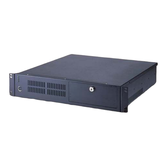
With its rugged, sturdy and well-cooled steel chassis specially designed to withstand heavy shocks and thick dust, the IPC-602 can be used in the harsh- est of environments. It is ideal for Computer Telephony or network system configurations that require high availability within a lim- ited space, such as computer telephony and networking systems. -
Page 11: Power Supply Options
1.2.2 Power Supply Options Part Number Watt Input Output Mini-load Safety MTBF PS-300ATX- 300 W DC -36 ~ -72 V +5 V @ 30 A +5 V @ 0.3 A UL/CSA/CE/TUV/ 100,000 hours DC48 +12 V @ 15 A +3.3V @ 0.3A @25°C -5 V @ 0.3 A +12V @ 0.2A... -
Page 12: Dimensions
1.3 Dimensions unit: mm [inch] Figure 1-1: Dimension Diagram IPC-602 User’s Manual... -
Page 13: Safety Precautions
1.4 Safety Precautions Warning! Always completely disconnect the power cord from your chassis whenever you work with the hardware. Do not make connections while the power is on. Sensitive electronic components can be damaged by sudden power surges. Only experienced electronics personnel should open the PC chassis. - Page 14 The user is advised that any equipment changes or modifications not expressly approved by the party responsible for compliance would void the compliance to FCC regulations and therefore, the user's authority to operate the equipment. IPC-602 User’s Manual...
- Page 15 System Setup Chapter 2...
-
Page 16: Chapter 2 System Setup
Chapter 2 System Setup 2.1 Introduction The following procedures are provided to assist you in installing drives and plug-in cards into the IPC-602. 2.2 Removing the Cover Unscrew the six screws on the front and rear panels, then slide the top cover toward the rear chassis and open it. -
Page 17: Installing Disk Drives
2.3 Installing Disk Drives After removing the cover, you can easily install disk drives. Please refer to Figure 2-2 below and do the following: 1. Remove the four outer screws which mount the drive bay to the chassis. 2. Slide the drive bay backwards to a location where it is not obstructed by the top rim. -
Page 18: Installing Plug-In Cards
Then replace the L-form support and fasten it. 4. After all cards are installed completely, put card cage back into the correct location in the chassis. Finally, fasten the screws. Figure 2-3: Installing plug-in cards IPC-602 User’s Manual... -
Page 19: Replacing The Fan
Figure 2-4: Replacing the fan 2.6 Replacing the Filter The filter is located next to the lockable door. If IPC-602 is under use constantly, the filter should be changed about once a month. To replace the filter, refer to Figure 2-5 below and do the following: 1. -
Page 20: Figure 2-5:Replacing The Filter
Figure 2-5: Replacing the filter 2.7 Installing the L form holder Before users mounting IPC-602 Chassis to the rack, please install the L form holders to both sides of the chassis. Please refer to Figure 2-6 and proceed as following steps. - Page 21 Optional Passive Backplanes Appendix A...
-
Page 22: Appendix A Optional Passive Backplanes
8-PIN +12V, -12V, +3.3V, +5V, -5V, GND and 5VSB connector 3-PIN PS_ON, GND and 5VSB for ATX power 3-PIN +12V, GND and +5V DC power connector To CPU card K/B connector To front part K/B connector ATX1 ATX Power connector IPC-602 User’s Manual... - Page 23 2. Pin Definition Name PS-ON Name 5VSB 5VSB Name +12V +3.3V -12V +12V FAN1 KB1, KB3 Name Name KBCLK +12V KB-DT ATX1 Name Name +3.3V +3.3V +3.3V -12V PS-ON 5VSB +12V 3. PCI Routing table PCI Slot ID SEL interrupt route INTA INTB...
-
Page 24: Pca-6106P3V: 1 Isa / 3 Pci / 2 Picmg Slots
AT power connector 90D VATX1 ATX Power connector 90D HCN1 PS-ON Function, to CPU card for ATX Power signal, 3 pin connector HCN2 8 pin Alarm Board Power connector HCN3 3 pin +5V and +12V Power connector IPC-602 User’s Manual... - Page 25 2. Pin Definition VKBA1,VKBA2,VKBA3; VATX1 Name Name KBCLK +3.3V KBDATA +3.3V KBGND KBVCC HCN1 Name PS-ON 5VSB +12V 5VSB +3.3V -12V HCN2 Name PS-ON 5VSB +3.3V -12V +12V VAT1 Name HCN3 Name +12V +12V -12V 3. PCI Routing table PCI Slot ID SEL interrupt route...
-
Page 26: Pca-6106Pv4: 1 Isa / 4 Pci / 1 Cpu Slots
KB-In, from CPU card K/B connector KB2~KB3 KB-Out, 5 pin external K/B connector PS-ON Function, to CPU card for ATX power signal, 3 pin 8 pin Alarm Board Power connector 8 pin +5V and +12V FAN connector IPC-602 User’s Manual... - Page 27 2. Pin Definition Name ATX1 PS-ON Name Name +3.3V +3.3V 5VSB +3.3V -12V PS-ON Name 5VSB 5VSB +12V +3.3V -12V +12V Name +12V KB~1/2/3 Name KBCLK KBDAT KBGND KBVCC 3. PCI Routing table PCI Slot IDSEL PCI Interrupt Pin Route INT A INT B INT C...
- Page 28 IPC-602 User’s Manual...
- Page 29 Parts Ordering Guide Appendix B...
-
Page 30: Appendix B Parts Ordering Guide
LED LAMP BRACKET HOLDER 9686610603 BACKPLANE 1994000060 2 LED HOUSING 1962002730 BRACKET 1759081200 DUAL FAN 1962011510 1 PCI CARD BRACKET 9692A10000 PS/2 K/B & 196202K130 1 CPU CARD USB PCB HOLDER 199902K000 FILTER PE 1995000090 FILTER HOUSING IPC-602 User’s Manual... - Page 31 1653104030 ATX POWER Code Part No. Q’ty Screw Descrip- SUPPLY tion 1703020550 WIRE MOUNT 193900036 HEX/W HOLE M3x0.5x5L 1601000001 RESET BUT- 1939006320 8 HEX/W#6-32 1602002100 POWER 1935330400 6 R/W M3x0.5x5L SWITCH 1962002770 SIDE FIXING 0939000410 8 R/W M4x0.7x5L HOLDER 1962002790 FRONT WIN- 1930030500 17 FLAT M3x0.5x5L...
- Page 32 IPC-602 User’s Manual...
-
Page 33: Safety Instructions
Safety Instructions Appendix C... -
Page 34: Appendix C Safety Instructions
The equipment has been exposed to moisture. The equipment does not work well, or you cannot get it to work according to the installation reference guide. The equipment has been dropped and damaged. The equipment has obvious signs of breakage. IPC-602 User’s Manual... -
Page 35: German - Wichtige Sicherheishinweise
The sound pressure level at the operator's position according to IEC 704- 1:1982 is equal to or less than 70 dB(A). DISCLAIMER: This set of instructions is given according to IEC 704-1. Advantech disclaims all responsibility for the accuracy of any state- ments contained herein. C.2 German - Wichtige Sicherheishinweise 1. - Page 36 60° C (140° F), weil diesen Temperaturen das Gerät zerstören könten. Der arbeitsplatzbezogene Schalldruckpegel nach DIN 45 635 Teil 1000 beträgt 70dB(A) oder weiger. DISCLAIMER: This set of instructions is provided according to IEC704-1. Advantech disclaims all responsibility for the accuracy of any statements contained herein. IPC-602 User’s Manual...
Need help?
Do you have a question about the IPC-602 and is the answer not in the manual?
Questions and answers