Table of Contents
Advertisement
Quick Links
Advertisement
Table of Contents

Subscribe to Our Youtube Channel
Related Manuals for Advantech IPC-603MB


Summary of Contents for Advantech IPC-603MB
- Page 1 IPC-603MB Ultra Compact 2U-high Rack- mount IPC Chassis User Manual...
- Page 2 No part of this man- ual may be reproduced, copied, translated or transmitted in any form or by any means without the prior written permission of Advantech Co., Ltd. Information provided in this manual is intended to be accurate and reli- able.
- Page 3 Product Warranty (2 years) Advantech warrants to you, the original purchaser, that each of its prod- ucts will be free from defects in materials and workmanship for two years from the date of purchase. This warranty does not apply to any products which have been repaired or...
-
Page 4: Declaration Of Conformity
This product has passed the CE test for environmental specifications when shielded cables are used for external wiring. We recommend the use of shielded cables. This kind of cable is available from Advantech. Please contact your local supplier for ordering information. - Page 5 Visit the Advantech web site at www.advantech.com/support where you can find the latest information about the product. Contact your distributor, sales representative, or Advantech's cus- tomer service center for technical support if you need additional assistance. Please have the following information ready before you...
- Page 6 SAME OR EQUIVALENT TYPE RECOMMENDED BY THE MANUFACTURER, DISCARD USED BATTERIES ACCORD- ING TO THE MANUFACTURER'S INSTRUCTIONS. The sound pressure level at the operator's position according to IEC 704- 1:1982 is no more than 70 dB (A). IPC-603MB User Manual...
- Page 7 DISCLAIMER: This set of instructions is given according to IEC 704-1. Advantech disclaims all responsibility for the accuracy of any statements contained herein. Wichtige Sicherheishinweise Bitte lesen sie Sich diese Hinweise sorgfältig durch. Heben Sie diese Anleitung für den späteren Gebrauch auf.
- Page 8 Der arbeitsplatzbezogene Schalldruckpegel nach DIN 45 635 Teil 1000 beträgt 70dB(A) oder weiger. Haftungsausschluss: Die Bedienungsanleitungen wurden entsprechend der IEC-704-1 erstellt. Advantech lehnt jegliche Verantwortung für die Richtigkeit der in diesem Zusammenhang getätigten Aussagen ab. Safety Precaution - Static Electricity Follow these simple precautions to protect yourself from harm and the products from damage.
-
Page 9: Table Of Contents
Installing Disk Drives............9 Installing Add-in Cards ........... 11 Installing Rackmount Brackets & Handles ..... 11 Chapter 3 Operation ............14 The Front Section of IPC-603MB........14 3.1.1 Switches ............... 14 3.1.2 LED indicators ............. 14 Table 3.1: System Status LED Summary ....14 Replacing the Fans ............ - Page 10 IPC-603MB User Manual...
- Page 11 General Information...
-
Page 12: Chapter 1 General Information
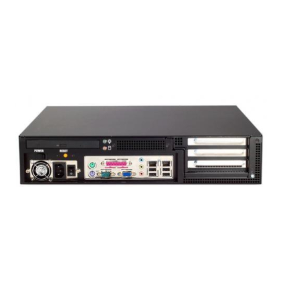
Chapter 1 General Information 1.1 Introduction IPC-603MB is an ultra compact 2U-high rackmount industrial computer chassis designed for space-conscious applications. With only 310 mm depth, IPC-603MB can accept any of Advantech ATX/mATX mother- boards, and up to three half-sized add-in cards with the supported riser card. -
Page 13: Environmental Specifications
1.3 Environmental Specifications • Temperature: (Operating) 0 ~ 40° C (32 ~ 104° F) (Storage) -20 ~ 60° C (-4 ~ 140° F) • Humidity: (Operating) 10 ~ 95% @ 40° C, non-condensing • Vibration (5 ~ 500 MHz): (Operating) 1Grms (Non-operating) 2 G •... -
Page 14: Dimensions Of Ipc-603Mb
1.5 Dimensions of IPC-603MB Figure 1-1 Dimension of IPC-603MB IPC-603MB User Manual... - Page 15 System Setup...
-
Page 16: Chapter 2 System Setup
Chapter 2 System Setup The following procedures are provided to assist you in installing a moth- erboard, drives, and add-in cards into an IPC-603MB chassis. Refer to Appendix A, Exploded Diagram, for the names of each part used in this manual. -
Page 17: Removing The Cover
2.1 Removing the Cover To remove the top cover of IPC-603MB, please refer to Figure 2-2. Figure 2-2 Removing the top cover 2.2 Installing a Motherboard IPC-603MB accepts both ATX and microATX motherboards. To install a motherboard, refer to Figure 2-1 and proceed as follows:... - Page 18 Check all devices, such as CPU, CPU cooler, and RAMs and make sure they have been installed on the motherboard correctly. Care- fully place the motherboard in the IPC-603MB chassis and fix it with screws. Note If you choose Advantech’s AIMB-740, 741, 742,...
-
Page 19: Installing Disk Drives
Re-install the L-form riser card holder (together with the riser card) and fasten it with screws. 2.3 Installing Disk Drives The IPC-603MB accepts one slim type CD-ROM/-RW and one internal SATA/ATA HDD. To install the disk drives, refer to Figures 2-4 and 2-5 and proceed as follows:... - Page 20 S l i m C D - R O M Figure 2-5 Place the drive bay bracket kit into IPC-603MB chassis Open the top cover of IPC-603MB chassis. Remove the four screws that mount the drive bay bracket kit in IPC-603MB chassis.
-
Page 21: Installing Add-In Cards
2.4 Installing Add-in Cards The IPC-603MB can accept up to three half-sized PCI add-in cards via the riser card, which is inserted in the sixth slot of the enclosed ATX motherboard and mounted on the L-form riser card bracket. To install an... - Page 22 IPC-603MB User Manual...
- Page 23 Operation...
-
Page 24: Chapter 3 Operation
Chapter 3 Operation 3.1 The Front Section of IPC-603MB 3.1.1 Switches Two switches are used for system power on-off and system reset. Press the System Reset Switch to reinitialize the system. Press the Power On- Off Switch to turn the system power on or off. -
Page 25: Replacing The Fans
3.2 Replacing the Fans There are two fans on the rear plate of IPC-603MB chassis. To change any failed fan, refer to Figure 3-1 and proceed as follows: Open the top cover of IPC-603MB chassis. Unplug the power connector of a failed fan from the motherboard and the fan filter behind the failed fan. -
Page 26: Replacing The Filters
3.3 Replacing the filters To change the filters, refer to Figure 3-2 and proceed as follows: Open the top cover of IPC-603MB chassis. Remove the filter(s) with two fingers and replace it with a new one. filter filter filter Figure 3-2 Changing the filters... -
Page 27: Replacing The Power Supply
3.4 Replacing the power supply IPC-603MB supports a single 1U-high power supply. To change the power supply, refer to Figure 3-3 and proceed as follows: Floppy Drive Power Connector +12V Power Connector Peripheral Power Connector ATX Power Connector Figure 3-3 Changing the power supply Unplug the power cord from the power supply of IPC-603MB. - Page 28 Plug the ATX power connector and +12V power connector into the motherboard, and the peripheral power connector(s) into the proper disk(s). Replace the cover of IPC-603MB and plug in the power cord. IPC-603MB User Manual...
- Page 29 Exploded Diagram...
-
Page 30: Appendix A Exploded Diagram
Appendix A Exploded Diagram IPC-603MB User Manual...
Need help?
Do you have a question about the IPC-603MB and is the answer not in the manual?
Questions and answers