Table of Contents
Advertisement
Advertisement
Table of Contents

Related Manuals for Advantech IPC-610-H


Summary of Contents for Advantech IPC-610-H
- Page 1 IPC-610-H 4U Rackmount Chassis User’s Manual...
- Page 2 Acknowledgments PC-LabCard is a trademark of Advantech Co., Ltd. IBM and PC are trademarks of International Business Machines Corporation. MS-DOS, Windows, Microsoft Visual C++ and Visual BASIC are trademarks of Microsoft Corporation.
- Page 3 On-line Technical Support For technical support and service, please visit our support website at: http://www.advantech.com/support Note: DDDDDDDDDDDDDDDDDDDDDDDDDDDDDDDDDDDDDDDDD DDDDDDDDDDDDDDDDDDDDDDDDDDDDDDDDDDDDDDDDD DDDDDDDDDDDDDDDDDDDDDDDDDDDDDDDDDDDDDDDDD DDDDDDDDDDDDDDDDDDDDDDDDDDDDDDDDDDDDDDDDD Part No. 2003178400 1st Edition Printed in Taiwan July 2002...
-
Page 4: Table Of Contents
Figure 2-1............8 2.1.3 Chassis Front and Rear Sections ......9 Figure 2-2............9 Figure 2-3............10 2.1.4 Drive Bay Installation ........10 Figure 2-4............11 2.2 IPC-610-H S ........ 12 ERIES NSTALLATION 2.2.1 IPC-610BP-00XH ..........12 2.2.2 IPC-610MB-00XH..........12 2.3 LED I... - Page 5 2.5 I CPU C & A ....15 NSTALLING ARDS ARDS APPENDIX A BACKPLANE............18 Figure 1.1 ............18 Table 1.1 Connectors........19 Table 1.2 Routing Table ........20...
- Page 7 General Information...
-
Page 8: Chapter 1 General Information
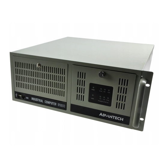
Chapter 1 General Information 1.1 Introduction IPC-610-H is a 4U height 14-slot rackmount IPC chassis designed for building mission-critical applications. The unit includes a versatile 14-slot passive-backplane by option (which supports ATX M/B form factor), a high-efficiency 300W ATX with power factor correction (PFC) power supply, and dual easy maintenance cooling fan which provides abundant cooling. -
Page 9: Passive Backplane Options
Storage temperature: -40° to +60°C (-40° to +140°F) Relative Humidity: 10 ~ 95%@40°C, non-condensing Vibration: (Operating) 5Hz ~ 500Hz, 0.5G rams Shock (operating): 2.0 G with 11m Sec duration, 1/2 sine wave Acoustic Noise: Less than 52 dB sound pressure at +5° to +28°C (+41°... -
Page 10: Power Supply Options
PS-250ATX-Z AC 95~132V +12V @ 13A +5V @ 0.5A UL/cUL/CSA/TUV/C 100,000 hours@25℃ 250 W (ATX,PFC) AC 190~264V -12V @ 0.8A +12V @ 0.3A B/CCC -5V @ 0.3A +5 Vsb @ 2 A Tablel 1-1 Installation Flow Chart IPC-610-H User's Manual... -
Page 11: System Regulation
1.5 System Regulation With Backplane or Model Name With Power Supply Regulation MotherBoard IPC-610P4-25ZH PS-250ATX-Z(ATX PFC) PCA-6114P4-C IPC-610BP-00XH None IPC-610BP-25ZH PS-250ATX-Z(ATX,PFC) w/o IPC-610BP-30ZH PS-300ATX-Z(ATX PFC) w/o IPC-610MB-00XH w/o None IPC-610MB-25ZH PS-250ATX-Z(ATX,PFC) w/o None IPC-610MB-30ZH PS-300ATX-Z(ATX PFC) w/o None Tablel 1-2 Installation Flow Chart 1.6 Dimensions Fig. -
Page 12: Exploded Diagram
1.7 Exploded Diagram Fig. 1-2 Installation Flow Chart IPC-610-H User's Manual... - Page 13 System Setup...
-
Page 14: Chapter 2 System Setup
First, remove the chassis cover. You don’t need any screwdriver. Top cover is fixed to the chassis by two thumbscrews To remove the top covers: 1. Release two thumbscrews on rear upper location the chassis. 2. Pull back and lift off the cover. Figure 2-1 IPC-610-H User's Manual... -
Page 15: Chassis Front And Rear Sections
2.1.3 Chassis Front and Rear Sections The front panel switches which behind the door are used for system power switch and system reset. The door cover is on the right side of door cover, there are system LED status and key lock switch. The USB and P/S 2 keyboard connector are on the left side of front panel. -
Page 16: Figure 2-3
14-slot I/O brackets and the sheet metal kit for section of M/B version includes M/B rear window, 7-slot I/O brackets, ATX M/B I/O cover. Figure 2-3 2.1.4 Drive Bay Installation The Standard Drive Bay of the IPC-610-H can hold 5.25” x 3 and 3.5” x 1 devices IPC-610-H User's Manual... -
Page 17: Figure 2-4
Installation disk drives 1. Remove the top cover 2. Undo the four screws of cushion and four screws fixing the Standard Drive Bay on right side 3. Lift off the Standard Drive Bay. See Figure 2-4 4. Insert the drives into their proper locations in the drive bay and secure them with the screws provided. -
Page 18: Ipc-610-H Series Installation
2.2 IPC-610-H Series Installation The IPC-610-H can be of two basic models, IPC-610BP-00XH and IPC-610MB-00XH. 2.2.1 IPC-610BP-00XH IPC-610BP-00XH has no backplane, no power supply and has momentary switch on front panel. The momentary switch is suitable for ATX power supply such as PS-250ATX-Z, PS-300ATX-Z. -
Page 19: Led Indicators
2.3 LED Indicators 2.3.1 System Status LED The System Status LED shows as following: Description GREEN System Power Normal Hard Drive Data access activity Tablel 2-1 2.3.2 Power Status LED The Power Status LED indicates the status of the backplane voltage signals. -
Page 20: Cooling Fan And Filter
Press the location A and then pull the B which is showed on Figure 2-6 then the connector could be released. Please refer Figure 2-7 to change the filter if you found the filter was blocked with dust or other particles Figure 2-5 Figure 2-6 IPC-610-H User's Manual... -
Page 21: Figure 2-7
Figure 2-7 2.5 Installing CPU Cards & Add-On Cards To install slot board computers and other add-on boards: Remove the chassis cover. Take out the hold down cramp Insert the CPU or add-on cards on suitable location Align and fix the screw to tighten the card to a fixed position Return the top cover after fix the hold down cramp... - Page 23 Backplane...
-
Page 24: Appendix A Backplane
Appendix A Backplane PCA-6114P4-C 26.5 8.25 2.54 12.7 20.32 40.94 20.32 20.32 78.74 16.51 21.3 64.5 71.68 45.72 Figure 1.1 IPC-610-H User's Manual... -
Page 25: Table 1.1 Connectors
1. Connectors Connector Description ISA1, 4~10 16 Bit ISA Bus connectorr PCI1~4 32 Bit PCI Bus connector ISA 2, 3 PICMG connector KB-In, from CPU card K/B connector KB2~KB3 KB-Out, 5 pin extemal K/B connector KB-Out, 6 pin PS/2 external K/ B connector BIG1 Big 4 Pin Power connectorr AT Power connector... -
Page 26: Table 1.2 Routing Table
INT D INT A PCI2 AD30 INT C INT B INT C INT D PCI3 AD29 INT D INT A INT B INT C PCI4 AD28 INT A INT B INT C INT D Table 1.2 Routing Table IPC-610-H User's Manual...
Need help?
Do you have a question about the IPC-610-H and is the answer not in the manual?
Questions and answers