
Related Manuals for Advantech IPC-622 Series


Summary of Contents for Advantech IPC-622 Series
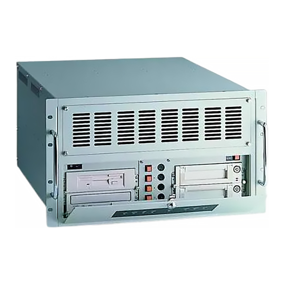
- Page 1 User Manual IPC-622 Series 6U, Multi-Segment, Rackmount Industrial Computer Chassis...
- Page 2 Advantech Co., Ltd. Informa- tion provided in this manual is intended to be accurate and reliable. However, Advan- tech Co., Ltd.
-
Page 3: Declaration Of Conformity
Declaration of Conformity This product has passed the CE test for environmental specifications. Test conditions for passing included the equipment being operated within an industrial enclosure. To protect the product from damage by electrostatic discharge (ESD) and electromag- netic interference (EMI) leakage, we strongly recommend using of CE-compliant industrial enclosure products. - Page 4 Technical Support and Assistance Visit the Advantech website at http://support.advantech.com to obtain the latest product information. Contact your distributor, sales representative, or Advantech’s customer service center for technical support if you need additional assistance. Please have the following information ready before calling: –...
-
Page 5: Safety Instructions
The sound pressure level at the operator position does not exceed 70 dB (A), as per the IEC 704-1:1982. DISCLAIMER: These instructions are provided in accordance with the IEC 704-1. Advantech disclaims all responsibility for the accuracy of any statements contained herein. IPC-622 User Manual... - Page 6 Safety Precautions - Static Electricity Follow these simple precautions to protect yourself from harm and the products from damage. To avoid electrical shock, always disconnect the power from the PC chassis before working on it. Do not touch any components on the CPU card or other cards while the PC is turned on.
-
Page 7: Table Of Contents
Contents Chapter General Information ......1 Introduction ....................2 Specifications .................... 2 Power Supply Options................3 Table 1.1: Power Supply Options ..........3 Environmental Specifications ..............3 Table 1.2: Environmental Specifications ........3 Dimension Diagram................... 4 Figure 1.1 Dimension diagram............. 4 Chapter System Setup ........5... - Page 8 Chapter Intelligent System Module (SAB-2000) .............21 Getting Started..................22 Specifications..................22 4.2.1 Hardware Specifications ............. 22 4.2.2 Dimensions ................. 22 4.2.3 Sensor Input Specifications ............22 4.2.4 System Status Monitoring and Management......22 4.2.5 Management Functions .............. 22 4.2.6 Alarm Notifications..............23 Table 4.1: LEDs and Beeps ............
-
Page 9: Chapter 1 General Information
Chapter General Information This chapter provides general information about the IPC-622. Introduction Specifications Power Supply Options Environmental Specifications Dimension Diagram... -
Page 10: Introduction
Introduction The IPC-622 is a 6U, rackmount industrial computer chassis designed for multi-sys- tem applications. The device supports a backplane with up to 20 slots for a quad-seg- ment industrial system, and can be configured to support a 400W, 500W, or 700W PS/2 power supply, or a 500W or 750W redundant power supply. -
Page 11: Power Supply Options
Power Supply Options Table 1.1: Power Supply Options Model 1757004407-01 1757004335-01 1757004336-01 1757004393-01 1757004588-01 Name Vendor FSP500- G.P, YH5751- FSP400-60PFG FSP500-60PFG FSP700-80PSA Name 80MRA(S) 1EA03R 500W Mini- 750W Mini- Watt 400W 500W 700W RPSU, 1+1 RPSU, 1+1 Input 90 ~ 264 V-rms 90 ~ 264 V-rms 90 ~ 264 V-rms 90 ~ 264 V-rms... -
Page 12: Dimension Diagram
Dimension Diagram 257.6 [10.14] 432.0 [17.01] 128.9 [5.07] 465.0 [18.31] 482.0 [18.98] 465.0 [18.31] 482.0 [18.98] Unit: mm [inch] Figure 1.1 Dimension diagram IPC-622 User Manual... -
Page 13: Chapter 2 System Setup
Chapter System Setup This chapter explains the installa- tion process. Backplane Installation CPU Card / Add-on Card Instal- lation Disk Drive Installation Ear and Handle Attachment... -
Page 14: Top Cover Removal
The following section outlines the procedures for installing the backplane, add-on cards, and disk drives into the IPC-622 chassis. Please refer to Appendix A, Exploded Diagram, for the specific names of the IPC-622 components. Caution! Use caution when installing or manipulating the components with the chassis open. -
Page 15: Backplane Installation
Backplane Installation The IPC-622 supports backplanes with up to 20 slots. To install a backplane, please refer to Figure 2.2 and proceed as follows: Attach the EMI spring shielding to the backplane. Place the backplane in the correct location and fasten to the chassis. For the PICMG1.0 backplane, connect the orange-white wire from connector HCN1 on the backplane to connector ATXF1 on the CPU card. -
Page 16: Cpu Card/Add-On Card Installation
CPU Card/Add-on Card Installation 2.3.1 Single CPU card/add-on card installation IPC-622 supports up to 20 add-on cards. To install a CPU card or add-on cards, please proceed as follows: Select a vacant PICMG slot for a full-length CPU card or PCI/ISA slot for add-on cards and remove the corresponding I/O bracket attached to the rear plate of the chassis. -
Page 17: Dual Cpu Card Installation On A Dual-Segment Backplane
2.3.2 Dual CPU Card Installation on a Dual-Segment Backplane Note! Before installing two CPU cards onto a dual-segment backplane, we recommend changing the system from ATX to AT mode by following the instructions below. Locate the green-black lines from the redun- dant power supply, and retrieve the AT switch from the accessory box. -
Page 18: Hold Down Clamp
2.3.3 Hold Down Clamp The hold down clamp is designed to protect CPU card from vibration and shock. Regarding PCIe card installation, one rubber foot is required to secure the add-on card into position. Figure 2.4 Top cover with rubber pad IPC-622 User Manual... -
Page 19: Installing Disk Drives
Installing Disk Drives The IPC-622 supports up to four 5.25" disk drives (for example, one CD-ROM drive, one CD-R/W drive, one DVD-ROM drive, and one removable disk drive). To install disk drives, follow the instructions below. Unscrew the four screws on the front of the disk drive shield. Hold the two thumb screws to remove the disk drive housing (Figure 2.5). -
Page 20: Ear And Handle Attachment
Ear and Handle Attachment A pair of ears and a pair of handles are provided in the accessory box. Fasten them to the front-right and front-left edges of the chassis with the screws provided. IPC-622 User Manual... -
Page 21: Chapter 3 Operation
Chapter Operation This chapter provides the system operation information. The Front Panel Cooling Fan Replacement Filter Cleaning Power Supply Replacement... -
Page 22: The Front Panel
The Front Panel The front panel features one Power On/Off switch, one Alarm Reset button, four Sys- tem Reset buttons, and four USB ports. Nine LED indicators are located on the lock- able front door; the individual functions of each are explained below. 3.1.1 Switch and Buttons Power On/Off switch: Press this button to turn the system power on or off. -
Page 23: Led Indicators For Power Status
3.1.3 LED Indicators for Power Status The LEDs that indicate the status of the backplane voltage signals are explained in the table below. Table 3.2: LED Indicators for Power Status Description LED on LED off +5 V +5 V signal Normal Abnormal +12 V... -
Page 24: Filter Replacement
Filter Replacement The filter blocks dust or particles in the work environment from entering the chassis and extends the system life. Ideally, the filters should be replaced periodically. One filter is located behind the front upper cover and one filter is located on the lower left and lower right sides of the front door. -
Page 25: Power Supply Replacement
Power Supply Replacement The IPC-622 supports either a PS/2 power supply or redundant power supply. To replace the power supply, follow the instructions below. 3.4.1 Redundant Power Supply Module The redundant power supply module is rear-accessible and hot-swappable. To change the module, follow the instructions below. Press the Alarm Reset button on the front panel to stop the alarm. -
Page 26: Power Supply Module
3.4.2 Power Supply Module For the PS/2 power supply module, following the instructions below to replace the power supply. Unplug the power cord from the power supply. Remove the top cover. Unplug the 12-pin AT power connector (or 20-pin (24-pin) ATX power connec- tor), 6-pin +3.3V, and 6-pin +5V power connectors from the backplane. -
Page 27: Figure 3.8 Replacing The Redundant Power Supply
Figure 3.8 Replacing the redundant power supply IPC-622 User Manual... - Page 28 IPC-622 User Manual...
-
Page 29: Chapter 4 Intelligent System Module (Sab-2000)
Chapter Intelligent System Module (SAB-2000) This chapter introduces the alarm board and thermal sensor specifi- cations. Getting Started Specifications Connectors and Switch Settings SAB-2000 Board Layout SAB-2000 Pin Definitions... -
Page 30: Getting Started
Getting Started Configuring SAB-2000 SAB-2000 is pre-installed in the system chassis. The hardware switch should be adjusted according to the system layout. Please refer to the user manual for the location of the hardware switch. For different system layouts, SAB-2000 can be configured using the H/W switch. Please refer to the “Switch Settings”... -
Page 31: Alarm Notifications
4.2.6 Alarm Notifications Table 4.1: LEDs and Beeps Item Status Criteria Beep Normal Normal Redundant power module Keep Warn fail beep Get IPMI and SUSI Blinking Keep Command to search Warn beep Normal Normal Data transferring Blinking Normal > 500 rpm Normal Keep CPU FAN fail... -
Page 32: Connectors And Switch Settings
Connectors and Switch Settings Table 4.2: Hardware Switch Label Function SW1 ~ 10 Hardware Switch Table 4.3: Connectors Label Function Thermistor Connector Thermistor Connector Thermistor Connector Thermistor Connector ALMRST1 Alarm Reset Connector IPMB1 IPMI module connector PMBUS1 PMBUS Connector LEBOARD1 LED Board Connector SMB_3V_1 SMBus Device Connector... -
Page 33: Table 4.4: Sw1 ~ 3
Table 4.4: SW1 ~ 3 SW1.Pin1 SW1.Pin2 SW1.Pin3 Cable Status MB FAN CPU TEMP No Connect Disable Disable Connect Disable Connect Disable Connect Connect Connect Connect Connect Table 4.5: SW4 ~ 6 SW1.Pin4 SW1.Pin5 SW1.Pin6 SYS FAN Qty Disable 1 (FAN1) 2 (FAN1~2) 3 (FAN1~3) 4 (FAN1~4) -
Page 34: Board Layout
Board Layout Figure 4.1 SAB-2000 connector locations Pin Definitions Table 4.8: SMB_MB1 Pin 1 I2C_SCLK Pin 2 I2C_SDAT Table 4.9: IPMB1 Pin 1 Pin 3 S_SDAT_R Pin 2 S_SCLK_R Pin 4 Table 4.10: PSBUS1 Pin 1 +V_PMBUS Pin 4 I2C_SDAT Pin 2 Pin 5 I2C_SCLK... -
Page 35: Table 4.13: Ledboard1
Table 4.13: LEDBOARD1 Pin 1 Pin 9 T-G_LED Pin 2 +V5_R Pin 10 T-F_LED Pin 3 +V12_R Pin 11 F-G_LED Pin 4 -V5_R Pin 12 F-F_LED Pin 5 -V12_R Pin 13 Pin 6 HDD_LED Pin 14 +V3.3_R Pin 7 P-G_LED Pin 15 +V5_SB_R Pin 8... -
Page 36: Table 4.22: Pwr1
Table 4.22: PWR1 Pin 1 +V12 Pin 4 Pin 2 Pin 5 IPC-622 User Manual... -
Page 37: Appendix A Exploded Diagram
Appendix Exploded Diagram... -
Page 38: Exploded Diagram
Exploded Diagram Figure A.1 Exploded diagram (1) Figure A.2 Exploded diagram (2) IPC-622 User Manual... -
Page 39: Appendix B Backplane Options
Appendix Backplane Options... -
Page 40: Backplane Options
Backplane Options The IPC-622 supports a variety of backplanes ranging from 18-slot to 20-slot. For detailed backplane specifications and information, please contact your local Advan- tech sales representative. Table B.1: PCIMG 1.0 Backplane Options Slots per Segment Segment PICMG PICMG/PCI PCA-6120P18 Single PCA-6120P12... - Page 41 IPC-622 User Manual...
- Page 42 No part of this publication may be reproduced in any form or by any means, including electronically, by photocopying, recording, or otherwise, without the prior written permission of the publisher. All brand and product names are trademarks or registered trademarks of their respective companies. © Advantech Co., Ltd. 2015...
Need help?
Do you have a question about the IPC-622 Series and is the answer not in the manual?
Questions and answers