Table of Contents
Advertisement
Quick Links
Advertisement
Table of Contents

Subscribe to Our Youtube Channel
Related Manuals for Xerox WorkCentre PE16


Summary of Contents for Xerox WorkCentre PE16
- Page 1 WorkCentre PE16 SERVICE Manual WorkCentre PE16 CONTENTS 1. Precautions 2. Reference Information 3. Specifications 4. Summary of product 5. Disassembly and Reassembly 6. Alignment and Adjustments 7. Troubleshooting 8. Exploded Views and Parts List 9. Block Diagram 10. Connection Diagram...
-
Page 3: Precautions
A personal injury hazard exists in the area where you see the sign. Symbols Marked on the Product Hot surface on or in the printer. Use caution to avoid personal injury. Use caution (or draws attention to a particular component). Refer to the manual(s) for information. Service Manual WorkCentre PE16 July 2003... -
Page 4: Laser Safety Statement
R PPNAD OCH SP RREN R URKOPPLAD. BETRAKTA EJ STR LEN. STR LEN R FARLIG. VARO! - AVATTAESSA JA SUOJALUKITUS OHITETTAESSA OLET ALTTIINA N KYM TT M LLE LASER- S TEILYLLE L KATSO S TEESEEN. Service Manual July 2003 WorkCentre PE16... -
Page 5: Power Source
■ if the equipment is dropped or damaged, ■ if you suspect that the product needs servicing or repair, ■ whenever you clean the product. Service Manual WorkCentre PE16 July 2003... - Page 6 ■ Handle IC’s and EPROM’s carefully to avoid bending pins. ■ Pay attention to the direction of parts when mounting or inserting them on Printed Circuit Boards (PCB’s). Service Manual July 2003 WorkCentre PE16...
-
Page 7: General Guidelines
Make sure all covers and the products’s front panel are in place and all interlock switches are functioning correctly after you have completed a unit service call. If you bypass an interlock switch during a service call, use extreme caution when working on or around the product. Service Manual WorkCentre PE16 July 2003... - Page 8 This product uses heat to fuse the toner image to media. The Fuser Assembly is VERY HOT. Turn the unit power off and wait at least 5 minutes for the Fuser to cool before you attempt to service the Fuser Assembly or adjacent components. Service Manual July 2003 WorkCentre PE16...
-
Page 9: Reference Information
(Isopropyl Alcohol) dry cloth or a liquid neutral detergent. Tweezers Standard: For general home use, small type. Software(Driver) installation CD Driver Standard : "-" type, "+" type (M3 long, M3 short, M2 long, M2 short). Service Manual WorkCentre PE16 July 2003... -
Page 10: Acronyms And Abbreviations
Samsung Printer Graphic Processor Hard Disk Drive Samsung Printer Language high voltage Spool Simultaneous Peripheral Operation Online HVPS High Voltage Power Supply Switch interface Sync Synchronous or synchronization Input and Output Universal Serial Bus integrated circuit Service Manual July 2003 WorkCentre PE16... - Page 11 The following test patterns are the standard patterns used to test the product in the factory. Cartridge life span and printing speed are measured with the patterns shown below. (The picture in the manual is 70% size of the actual A4 size.) 2.3.1 A4 5% Pattern Service Manual WorkCentre PE16 July 2003...
- Page 12 Reference Information 2.3.2 A4 2% Pattern Service Manual July 2003 WorkCentre PE16...
- Page 13 Reference Information 2.3.3 A4 IDC 5% Pattern Service Manual WorkCentre PE16 July 2003...
- Page 14 Reference Information Service Manual July 2003 WorkCentre PE16...
-
Page 15: Specifications
Normal 600 *600dpi Toner Save Memory 8 MB FPOT Stand by Approx. 12 seconds Power Save Less than 54 seconds Printable Area 208 X 271 mm (Letter) 202 X 289 mm (A4) Toner Save Service Manual WorkCentre PE16 June 2003... -
Page 16: Scan Specification
Letter : 125 sec, A4 : 130 sec & 300dpi.(USB) Resolution Optical 600 dpi Enhanced 4800 dpi Halftone 256 level Scan Width Width Max.216mm (8.5") Length(Adf) Max. 356mm (14.0") Length(Platen) Max. 297mm (11.7") Scan-to E-mail, Image, OCR, FAX, WEB From SmarThru3 Service Manual June 2003 WorkCentre PE16... -
Page 17: Copy Specification
3 level(by LED) Copy Mode TEXT/MIXED/PHOTO Collation Copy Yes(300dpi only) Auto return to default mode Yes(after 1 minute) N-up copy 2-up, 4-up ADF Only AutoFit Copy Platen Only Clone Platen Only Poster Platen Only Service Manual WorkCentre PE16 June 2003... -
Page 18: Telephone Specification
Report & List Print out Tx/Rx Journal Confirmation 2 types available (with Image TCR, w/o image TCR) Help List Auto Dial List System Data List List all user setting Sound Control Ring Volume Yes(Off,Low,MED,HIGH) Key Volume Yes(On,Off) Speaker Yes(On,Off) Service Manual June 2003 WorkCentre PE16... -
Page 19: Fax Specification
Up to 99 locations Forced Memory TX Cover page Delayed fax Memory RX Functions Voice Request Polling Earth/Recall Auto Reduction Junk Fax barrier Security Mode Battery Backup Yes (Min. 15 minutes) Not Battery (Using Super Cap.) Service Manual WorkCentre PE16 June 2003... -
Page 20: Paper Handling
Win 3.x Win 95 Win 98&WinME Win NT 4.0 Win 2000 Win XP WHQL for Printer Only Mac Printer Only Linux Driver Printer SPL(GDI) TWAIN PC-FAX PC Fax is only avail- able through PC Modem Service Manual June 2003 WorkCentre PE16... - Page 21 Specifications 3.9 Consumables Items Descriptions Remarks Type Single Cartridge How to install Front door open and front loading Toner Life Initial 2,000 sheets IDC 5% running 3,500 sheets character printing Level Sensor Toner Count Service Manual WorkCentre PE16 June 2003...
- Page 22 Specifications Service Manual June 2003 WorkCentre PE16...
-
Page 23: Summary Of Product
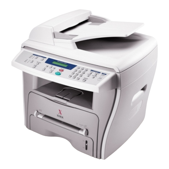
4.1 Printer Components 4.1.1 Front View Document Document Cover Guides Document Automatic Input Tray Document Feeder Document Glass Document Output Tray Control Panel Front Cover Paper Output Extension Paper Tray Paper Level Indicator Bypass Tray Service Manual WorkCentre PE16 July 2003... -
Page 24: Rear View
Summary of Product 4.1.2 Rear View Rear Cover Rear Output Slot (Face up) Parallel Power Switch Telephone Line Connector Connector AC Power Cord Connector Connector Service Manual July 2003 WorkCentre PE16... -
Page 25: Control Panel
Sends you back to the upper menu level. Stops an operation at any time. In Standby Mode, clears/cancels the copy options, such as the contrast, the image setting, the copy size and the number of copies. Starts a job. Service Manual WorkCentre PE16 July 2003... - Page 26 Allows you to save on toner by using less toner to print a document. Allows you to save on call costs by sending a fax at a preset toll-saving time. Using this feature, you can take advantage of lower long distance rates at night, for example. Service Manual July 2003 WorkCentre PE16...
-
Page 27: System Layout
4.2.4.4 Pressure roller The pressure roller mounted right under the heat roller is made of the silicon resin. The toner fuses onto the paper when it passes between the heat roller and the pressure roller. Service Manual WorkCentre PE16 July 2003... - Page 28 1.Operating frequency: 66 MHz 2.Image sensor interface: 200/300/600 dpi CIS or CCD 3.Line time: Copy, FAX, Binary (Lineart, Halftone) PC Scan: 1.5ms/Line Color PC Scan (Grey, 256 Color, True Color): 4.5ms/Line 4.A/D conversion: 10bit conversion Service Manual July 2003 WorkCentre PE16...
- Page 29 After detecting the /HSYNC signal, the image data is sent to the LSU to begin transfer of the image left margin to the paper. Each surface of the polygon mirror provides one line for scanning. Service Manual WorkCentre PE16 July 2003...
-
Page 30: Toner Cartridge
- Management of excess toner: Collect the toner by using electric charge (Cleanerless Type- No excess toner) - OPC Drum protecting Shutter: None - Classifying device for toner cartridge: ID is classified by interruption of the frame channel. Service Manual July 2003 WorkCentre PE16... -
Page 31: Main Pba
ASIC SUPER1284 BUFFER EXPANSION I/O MODEM CLOCK MOTOR DRIVE IC (INVERTER) (HCT273) U44/ CN13 U43/ U41 CN14 OSC2 OSC3 CN12 U75/ CN10 CN7 CN9 U118 U113/U114 OSC5 U95/ U125 U115 U135 U134 U120 U123 Service Manual WorkCentre PE16 July 2003... -
Page 32: Flash Memory
• Capacity : 0.5 M Byte • Access Time : 70 nsec 4.3.3 SDRAM The SDRAM is used as a buffer, system working memory area, etc. while printing. • Access Time : 60 nsec Service Manual 4-10 July 2003 WorkCentre PE16... -
Page 33: Sensor Input Circuit
The motor driving circuit is formed when the Driver IC is selected. The A3977 (Motor driver IC) is used in this case. The resistance Rs value of sensing and the voltage value of the V reference can be changed by the motor driving voltage value. Service Manual 4-11 WorkCentre PE16 July 2003... - Page 34 The HVPS creates the high voltage for THV/MHV/Supply/Dev and supplies it to the developer to be used in optimizing the image display. The HVPS uses the 24V as an input and outputs the high voltage for THV/MHV/BIAS, toner, OPC cartridge, and transfer roller. Service Manual 4-12 July 2003 WorkCentre PE16...
- Page 35 - Output voltage: : -630V DC ± 50V (Use ZENER, DEV Gear) - Error: 1. If SUP is GND, a density is reduced significantly. 2. If SUP is floating due to poor ground contact, etc., density drops to to almost non-existant levels. Service Manual 4-13 WorkCentre PE16 July 2003...
- Page 36 1.5 A 0.5A 1.5 A 1.0 A AVG : 350 Wh Sleep-Mode 0.3A 0.0A 0.0A 0.06A AVG : 20 Wh 4) Length of Power Cord : 1830 ± 50mm 5) Power Switch : Service Manual 4-14 July 2003 WorkCentre PE16...
-
Page 37: Fuser Ac Power Control
1) Triac (THY1) feature - 12A,600V SWITCHING 2) Phototriac Coupler (PC3) - Turn On If Current : 15mA ~ 50mA(Design: 16mA) - High Repetitive Peak Off State Voltage : Min 600V Service Manual 4-15 WorkCentre PE16 July 2003... - Page 38 AD converter. The voltage value for impressing to the transfer roller is decided by the changed value. Service Manual 4-16 July 2003 WorkCentre PE16...
- Page 39 Error Description Polygon motor error When the polygon motor does not reach normal speed Hsync error The polygon motor speed is normal, but the Hsync signal is not created. Service Manual 4-17 WorkCentre PE16 July 2003...
-
Page 40: Liu Pba
OPE board consists of various function keys and LCDs to display key operations. MICOM creates a circuit using HT48R50 MICOM of HOLTEC CO. and applies LED and LCD. The communication method with the Main Board CPU is a UART, and related signals are /Reset, TXD, and RXD. Service Manual 4-18 July 2003 WorkCentre PE16... -
Page 41: Disassembly And Reassembly
4. Use a flat and clean surface. 5. Replace only with authorized components. 6. Do not force plastic-material components. 7. Make sure all components are in their proper position. 8. Observe ESD precautions when handling sensi- tive electronic components. Service Manual WorkCentre PE16 July 2003... -
Page 42: Rear Cover
3. Unlatch the (Cover Face Up) securing the Rear cover, as shown below.Then lift the (Cover Face Up) out. Cover Face Up 2. Remove the Rear Cover from the Frame Ass'y and Scanner Ass'y. Rear Cover Service Manual July 2003 WorkCentre PE16... - Page 43 3. Pull down and back on the LH and RH Side Covers should remove: and lift them out in the direction of the arrows. - Rear Cover (see page 5-2) Side Cover(LH) 2. Unplug the Speaker Harness, as shown below. Speaker Harness Side Cover(RH) Service Manual WorkCentre PE16 July 2003...
-
Page 44: Front Cover
Disassembly and Reassembly 5.4 Front Cover 1. Take out the Cassette. 3. Unlatch the Front Cover securing the Frame Ass'y. Then remove the Front Cover, as shown below. Cassette Front Cover 2. Open the Front Cover. Service Manual July 2003 WorkCentre PE16... - Page 45 3. Unplug the four connectors from the Connector PBA , 5. Disconnect the cover wiring harness then pull the as shown below, and remove the ground wire. Platen Cover upward and remove it. Connection Board Connection Board Service Manual WorkCentre PE16 July 2003...
- Page 46 7. Lift the OPE Unit out. Then unplug the two connec- tors from the OPE Unit and remove it. 9. Unlatch the Scan Upper securing the Scan Ass’y Then pull the Scan Upper upward and remove it. Scan Upper Service Manual July 2003 WorkCentre PE16...
- Page 47 12. Pull up the CCD Shaft and take out the Scanner Module. Scanner Module CCD Cable CCD Shaft Belt Holder 11. Push the Belt Holder and take out the Belt, as shown below. Belt Service Manual WorkCentre PE16 July 2003...
- Page 48 14. Remove the two screws and take out the Motor 16. Unlatch the Open Sensor and remove it, as shown Bracket. below. Motor Bracket Open Sensor 15. Unplug the one connector from the Open Sensor Ass'y. Service Manual July 2003 WorkCentre PE16...
- Page 49 Open Cover ADF Motor Ass’y ADF Lower Ass’y 4. Pull the White Bush, then rotate it until it reaches the slot, as shown below. Then lift the Pick-Up Ass'y out. Pick up Ass’y White Bush Service Manual WorkCentre PE16 July 2003...
-
Page 50: Ope Unit
1. Remove the seven screws securing the OPE PBA 3. Remove the Key Pad from the OPE Cover. to the OPE Cover. OPE Cover OPE PBA Key Pad 2. Remove the Contact Rubber from the OPE Cover. Contact Rubber Service Manual 5-10 July 2003 WorkCentre PE16... - Page 51 5. Remove the Exit Gear, Bearing and Exit Roller as shown below. Exit Gear 3. Unlatch the Middle Cover Securing the Frame Ass'y, Bearing using a proper tool as shown below. Then lift the Exit Roller Middle Cover out. Middle Cover Service Manual 5-11 WorkCentre PE16 July 2003...
- Page 52 2. Remove the two screws securing and unplug the FPC cable From the Main PBA. Then remove the LIU PBA LIU PBA Engine Shield Ass’y 3. Unplug the two connectors. Thermistor connector Fan Connector Service Manual 5-12 July 2003 WorkCentre PE16...
- Page 53 1. Before you remove the Main PBA, you should remove: - Engine Shield Ass’y(see page 5-12) Main PBA 2. Unplug the one connector and remove the five screws securing the Main PBA. Then lift the Main PBA out, as shown. Service Manual 5-13 WorkCentre PE16 July 2003...
- Page 54 SMPS out, as shown below. SMPS 2. Remove the three screws securing the Inlet Bracket and remove it Inlet Bracket 3. Unplug the one connector and remove the one screw securing the Engine Shield. Service Manual 5-14 July 2003 WorkCentre PE16...
- Page 55 Idle Gear 3. Remove the two screws securing the Thermostat. Then lift the Thermostat out Thermostat 6. Remove the four screws securing the Fuser Cover and remove it, as shown below. Claw Fuser Cover Service Manual 5-15 WorkCentre PE16 July 2003...
- Page 56 Disassembly and Reassembly 7. Unwrap the Thermister Harness, as shown below. 8. Remove the one screw securing the Thermister and remove it, as shown below. Thermister Harness Thermister Service Manual 5-16 July 2003 WorkCentre PE16...
- Page 57 1. Before you remove the Fan, you should remove: 2. Unplug the connector from the SMPS and remove the - Rear Cover (see page 5-2) one screw. Then take out the Fan. - Side Cover (RH) (see page 5-3) DC Fan Service Manual 5-17 WorkCentre PE16 July 2003...
- Page 58 3. Take out the Drive Ass'y, then unplug the connector remove: from the Main PBA, as shown below. - Rear Cover (see page 5-2) - Side Cover (LH) (see page 5-3) 2. Remove the six screws securing the Drive Ass'y. Drive Ass’y Service Manual 5-18 July 2003 WorkCentre PE16...
- Page 59 2. Remove the three screws securing the Transfer Earth and remove it. Transfer Earth 4. Unlatch the Bushing and remove it. Then lift the Transfer Roller out, as shown below. Transfer Roller Bushing Service Manual 5-19 WorkCentre PE16 July 2003...
- Page 60 Guide paper 5. Remove the Idle Gear and Feed Gear2. Feed Gear2 3. Pull up the Feed Idle Bushing and Feed Idle Shaft, as shown below. Feed Idle Idle Gear Shaft Bushing Service Manual 5-20 July 2003 WorkCentre PE16...
- Page 61 Disassembly and Reassembly 6. Remove the Feed Gear1 Ass'y. 7. Pull up the Feed Roller and Feed Roller1. Feed Roller Feed Gear1 Ass’y Feed Roller1 Service Manual 5-21 WorkCentre PE16 July 2003...
- Page 62 5. Remove the two screws securing the Manual Solenoid and Pick-Up Solenoid. Then remove Manual Solenoid and Pick-Up Solenoid. 3. Remove the Pick-Up Gear Ass,y. (Pick up) Solenoid Pick up Gear (Manual) Ass’y Solenoid Service Manual 5-22 July 2003 WorkCentre PE16...
-
Page 63: Alignment And Adjustments
DCU using method, Jam removing method, and so on. 6.1 Paper path Scanner Part Doc-Paper(30Sheets) Sensor-Regi Sensor-Regi Sensor-Doc Sensor-Doc Sensor-Scan White-Sheet White-Sheet CCD-Module Engine Part L S U Fuser Toner Cartridge Service Manual WorkCentre PE16 June 2003... -
Page 64: Printer Paper Path
ALIGNMENT & A D J U S T M E N T S 6.1.1 Copy & Scan Document Path Scanner Part White-Sheet White-Sheet CCD-Module 6.1.2 Printer Paper Path 1) After receiving a print job, the printer feeds the paper from the cassette or manual feeder. 2) The fed paper passes the paper feeding sensor. -
Page 65: Clearing Paper Jams
The covering of a metal part can be removed which can cause an electric leakage. L S U L S U Fuser Toner Cartridge Fuser Toner Cartridge Paper Jam0 Paper Jam1 L S U L S U Fuser Toner Cartridge Fuser Toner Cartridge Paper Jam2 Bypass Jam Service Manual WorkCentre PE16 July 2003... -
Page 66: Clearing Document Jams
3) Close the ADF top cover. Then load the documents back into the ADF. NOTE : To prevent document jams,use the document glass for the thick, thin or mixed documents. 2) Pull the document gently to the right and out of the ADF. Service Manual July 2003 WorkCentre PE16... - Page 67 Remove the document from the ADF or the feed area by carefully pulling it towards the right by using both hands. 3) Close the document cover. Then load the documents back into the ADF. Service Manual WorkCentre PE16 July 2003...
- Page 68 3) Remove the jammed paper by gently pulling it straight out. If there is any resistance when you pull the paper, or the paper is not seen in this area, skip to the fuser area around the toner cartridge Service Manual July 2003 WorkCentre PE16...
- Page 69 6) Open and close the front cover to resume printing. 3) If there is any resistance when you pull the paper, or the paper is not seen in the front output tray, open the rear cover. Service Manual WorkCentre PE16 July 2003...
- Page 70 1) Open the front cover and remove the toner cartridge. 3) Replace the toner cartridge and close the front cover. Printing automatically resumes. 2) Remove the jammed paper by gently pulling it straight out. Service Manual July 2003 WorkCentre PE16...
-
Page 71: Tips For Avoiding Paper Jams
• Use only recommended print materials. See “Paper Specifications ” • Ensure that the recommended print side is facing down when loading paper in the paper tray and facing up in the Bypass tray. Service Manual WorkCentre PE16 July 2003... -
Page 72: User Mode
Junk Fax List ECM Mode 7.Sound/Volume 8.Machine Setup 9.Maintenance Speaker Machine ID Clean Drum Ringer Date&Time Notify toner Key Sound Clock Mode Clear Memory Alarm sound Dial Mode Language Power Save CCD Power Save USB Mode Service Manual July 2003 WorkCentre PE16... -
Page 73: Tech Mode
To enter the Tech mode To enter the Tech mode, press in sequence, and the LCD briefly displays ‘TECH’, the machine has entered service (Tech) mode. 6.4.2 Setting-up System in Tech Mode WorkCentre PE16 Service Manual WorkCentre PE16 July 2003... -
Page 74: Data Setup
Brazil France Oman Italy Poland Spain Bangladesh Austria Kuwait Netherlands Moroco Belgium Algeria Country Portugal Pakistan Sweden Norway Bahrain Denmark Srilanka Finland SaudiArabia Switzerland Chile Greece Peru Ireland Argentina Turkey Hungary Romania Bulgaria Czech Service Manual July 2003 WorkCentre PE16... -
Page 75: Flash Upgrade
1. sending and receiving fax must be the same model. 2. A sending fax must be set up in ECM mode, and receiving memory must be set up as 100%. If not, the function will operate abnormally. Service Manual WorkCentre PE16 July 2003... -
Page 76: Machine Test
3. After the scan, CCD SHADING PRO- FILE will be print out. 4. If the printed image is different to the image, the CCD is defect. NOTE : When you test CCD, make sure that the cover is closed. Service Manual July 2003 WorkCentre PE16... -
Page 77: Protocol List
Use this list to check for send and receive errors. If a communication error occurs while the machine is in TECH mode, the protocol list will print automatically. SYSTEM DATA This feature provides a list of the user system data settings and tech mode settings. Service Manual WorkCentre PE16 July 2003... -
Page 78: Engine Test Mode
1 : On, 2 : Off (+1300V ± 20V) THV ADC 1300V 1 : On, 2 : Off (ADC Value : 101 ± 5) THV ADC 600V~3500V 1 : On, 2 : Off (Compare each ADC Value) Service Manual July 2003 WorkCentre PE16... -
Page 79: Identify Sale Date
Press MENU, #, 1, 9, 3, # in sequence.Firmware version is displayed on LCD. Press 1( in the number keypad) : The LCD display shows "Updated date" Press 2( in the number keypad) : The LCD display shows "Product first use date" Service Manual WorkCentre PE16 July 2003... -
Page 80: Consumables And Replacement Parts
COMPONENT REPLACEMENT CYCLE ADF Rubber 20,000 Pages ADF Roller 60,000 Pages Pick-up Roller 60,000 Pages Friction Pad 60,000 Pages Transfer Roller 60,000 Pages Fuser 60,000 Pages Toner Cartridge 3,500 Pages (A4 IDC 5% Pattern) Service Manual July 2003 WorkCentre PE16... -
Page 81: Abnormal Image Printing And Defective Roller
Black spot Supply Roller 37.0mm Horizontal density band Develop Roller 35.2mm Horizontal density band Transfer Roller 45.3mm Black side contamination/transfer fault Heat Roller 66.3mm Black spot and fuser ghost Pressure Roller 75.5mm Black side contamination Service Manual WorkCentre PE16 July 2003... -
Page 82: Error Messages
Solution : Load a document and try again. MEMORY FULL Meaning : The memory has become full. Solution : Either delete unnecessary documents, or retransmit after more memory becomes available, or split the transmission into more than one operation. Service Manual July 2003 WorkCentre PE16... - Page 83 Solution : Toner may be unevenly distributed. Remove the toner cartridge and shake it gently to evenly dis- tribute the toner. Then replace the toner cartridge and retry. Scanner Locked Meaning : Scanner is locked by locker. Solution : Check locker. Connect the Flat-Cable. Service Manual WorkCentre PE16 July 2003...
- Page 84 ALIGNMENT & A D J U S T M E N T S Service Manual July 2003 WorkCentre PE16...
-
Page 85: Troubleshooting
3. Clean with soft cloth dampened with IPA(Isopropyl Alcohol) or water. 4. If the paper feeds into the printer and 4. Replace the Housing-Pickup and/or Jam 0 occurs, perform DCU to Shaft-Pickup. check feed-sensor of the engine board. Service Manual WorkCentre PE16 July 2003... - Page 86 3. Remove the jammed paper after disas- sembling the fuser : Clean the surface of the pressure roller with dry gauze. • Remove the toner particles stained on the rib. • Check the assembly and perfor- mance of the exit. Service Manual WorkCentre PE16 July 2003...
-
Page 87: Paper Rolled In The Fuser
(Background, Hot off set) Heat-roller and and remove the foreign matter off of the pressure roller. 2. If background appears badly in the printing, fix it by referring to the solutions for background. (See 7.3.8 Background) Service Manual WorkCentre PE16 July 2003... -
Page 88: Defective Adf
1. Check if ADF rubber and HOLDER rubber are dam- 1. Replace the contaminated or damaged part. aged. 2. Check if the document sensors of ADF Ass’y 2. Replace the ADF ASS’Y. (3 paper sensors) are normal. Service Manual WorkCentre PE16 July 2003... - Page 89 1. Disassemble and reassemble the OPE Ass'y. Replace defective part. 2. Confirm you can hear a click sound, while pressing a key 2. Replace the OPE Ass'y and the Main PBA in on the OPE panel. sequence. Service Manual WorkCentre PE16 July 2003...
-
Page 90: Paper Empty
1. Bending or deformation of the actuator of the paper sen- 1. Replace the defective actuator. sor. 2. The function of the Main PBA is defective Perform 2. Replace the Main PBA. Engine Test Mode : Perform Engine Test Mode diagnos- tic code 2. Service Manual WorkCentre PE16 July 2003... -
Page 91: Door Open
Check and Cause Solution Check the Connector(CN1) and Circuit of the Cover Switch 1. Check the insertion of the Door S/W Connect. department in the Main PBA. 2. Replace the Main PBA or Door Open S/W. Service Manual WorkCentre PE16 July 2003... -
Page 92: Defective Motor Operation
1. Replace the power supply cord or SMPS. 2. Check inside the LED-Panel on the front-cover, if the 2. Replace the control board. LED-Panel does not appear after normal warm-up. 3. Replace the LED-panel. Service Manual WorkCentre PE16 July 2003... - Page 93 1. If the supply of +24v is unstable in the Main Control board 1. Replace LSU. linking with LSU, check drive by Engine Test Mode : Diagnostic Code 1 LSU Motor on. 2. Replace the Main Control board. Service Manual WorkCentre PE16 July 2003...
-
Page 94: Printing Quality Problems
4. Open the front cover and check odically at the top of a black image. that the ribs corresponds to the position of the lines. 5. If the problems are not solved, replace the developer cartridge. Service Manual 7-10 WorkCentre PE16 July 2003... -
Page 95: Horizontal Black Band
4. In case of 37.7 mm interval not removable in 1, replace the developer cartridge and try to print out. 5. Clean paper particles and foreign matter from the inside of the machine. Service Manual 7-11 WorkCentre PE16 July 2003... -
Page 96: Light Image
Developer and charge terminal of HVPS. 3. If steps 1 and 2 above did not correct the problem, replace the HVPS . Service Manual 7-12 WorkCentre PE16 July 2003... -
Page 97: Uneven Density
3. The vertical movement of the transfer 3. Clean the bush part of the transfer roller. roller is too great? 4. The HVPS is normal? 4. Replace the HVPS. (Perform Engine Test Mode diagnostic code 4) Service Manual 7-13 WorkCentre PE16 July 2003... - Page 98 OHP, the software application and after use, we rec- Digital Printer higher transfer voltage is required. ommend returning to the original Mode. Digital Printer Digital Printer Digital Printer Service Manual 7-14 WorkCentre PE16 July 2003...
- Page 99 PC Cleaning Mode Print 2 or 3 times. And Digital Printer perform Self-Test 2 or 3 times to remove contamination. 3. Replace the Transfer Roller.. Service Manual 7-15 WorkCentre PE16 July 2003...
- Page 100 Mode diagnostic Mode code 0 if the Pick-up correctly. Solenoid is normal. 3. If not solved by the Steps1-2, replace the engine board. 4. Turn the power off, clear the print job on the computer, and try printing again. Service Manual 7-16 WorkCentre PE16 July 2003...
-
Page 101: No Dial Tone
3. Check the connection of HARNESS between the 3. If the problem still persists, replace the LIU and the LIU and the Main PBA. Main PBA in that order. Notes: Product supports the MF DIAL type only. Service Manual 7-17 WorkCentre PE16 July 2003... - Page 102 2. Check the RECEIVE condition by trying to send a FAX to another fax machine from the sending FAX. 3. Check if the telephone line is connected to the product. Check if it has excessive noise. Service Manual 7-18 WorkCentre PE16 July 2003...
- Page 103 Check if the RECEIVE Mode is TEL MODE or FAX After the RECEIVE mode is changed to FAX MODE, if it MODE. cannot receive, replace the LIU PBA and the Main PBA in sequence. Service Manual 7-19 WorkCentre PE16 July 2003...
-
Page 104: Defective Automatic Receiving
1. If the RECEIVE Mode is set to the TEL MODE, reset it MODE. to the FAX MODE. 2. After the RECEIVE mode is changed to FAX MODE, if it cannot receive, replace the LIU PBA and the Main PBA in sequence. Service Manual 7-20 WorkCentre PE16 July 2003... -
Page 105: Copy Problems
Black page is printed out when Copying. Check and Cause Solution 1. Check the CCD problem in Main PBA. 1. Check the CCD harness contact. 2. Check shading profile. 2. Remake shading profile in the tech mode. Service Manual 7-21 WorkCentre PE16 July 2003... -
Page 106: Defective Image Quality
1. Remake shading profile in the Tech Mode. 2. A gap exceeding 0.5 mm can cause a blurred image. 2. Check the gap between original and scanner glass. 3. See “Printing Quality Problems”. 3. Check printing quality. Service Manual 7-22 WorkCentre PE16 July 2003... -
Page 107: Scanning Problems
CCD Ass’y. 2. Check if the resolution is set too low in PC Scan 2. If the resolution is set too low, refer the user to the options. (Refer to User's Manual.) User's Manual. Service Manual 7-23 WorkCentre PE16 July 2003... -
Page 108: Service For The Life Of Toner Cartridge
Troubleshooting 7.7 Toner Cartridge Service This product should only be used with Xerox Toner Cartridges specified in this document and the User Manual. 7.7.1 Precautions on Safe-keeping of Toner Cartridge Exposure to direct light for more than a few minutes may cause damage to the cartridge. -
Page 109: Signs And Measures At Poor Toner Cartridge
(1)Check whether foreign sub- stances or toner are stuck to the terminal (contact point) of the toner cartridge. (2)Check whether the state of the terminal assembly is normal. Service Manual 7-25 WorkCentre PE16 July 2003... - Page 110 Exchange the transfer roller irregular intervals, the transfer because the life of the transfer roller's life has expired or the roller has been exceeded. transfer voltage is abnormal. (Exchange the SMPS PBA) Service Manual 7-26 WorkCentre PE16 July 2003...
- Page 111 Clean the terminals on the terminal (point of of the developing roller, then contact) of the developer and recheck it. for damage to the assembly. (Especially check the developing roller terminal.) Service Manual 7-27 WorkCentre PE16 July 2003...
- Page 112 Troubleshooting Service Manual July 2003 WorkCentre PE16...
-
Page 113: Exploded Views And Parts List
8.9 Cassette Ass’y Exploded view ........page(8-20) Service Manual WorkCentre PE16 June 2003... -
Page 114: Main Assembly
E X P LO D E D VIEW & PA RTS LIST 8.1 Main Assembly Service Manual June 2003 WorkCentre PE16... - Page 115 E X P LO D E D VIEW & PA RTS LIST Main Assembly Parts List Description Part Number Q’ty Remark WorkCentre PE16 ELA HOU-UNIT SCAN 500 N 00105 COVER-LCD WINDOW Not Spared ELA HOU-ADF 101 N 01337 AS-ELA HOU-OPE(XEROX)
- Page 116 030 N 00654 MEA UNIT-SHIELD ENGINE 055 N 00277 25-1 “SHIELD-ENGINE, ROCKY” Not Spared 25-2 SUPPORTER Not Spared CBF HARNESS-SCAN 152 N 11462 SUPPORTER 030 N 00655 CBF-HARNESS-DUPLEX GND 152 N 11463 SHEET-OVERLAY(XEROX) 002 N 02194 Service Manual June 2003 WorkCentre PE16...
- Page 117 GEAR-RDCN 53/26 Not Spared GEAR-RDCN 113/33 Not Spared GEAR-RDCN 57/18 Not Spared WASHER-PLAIN Not Spared BRACKET-P-MOTOR 1400 Not Spared GEAR-RDCN 103/41 Not Spared GEAR-RDCN 90/31 Not Spared MOTOR STEP-HUMMINGBIRD Not Spared PMO-IMPELLER_DRV Not Spared Service Manual WorkCentre PE16 June 2003...
-
Page 118: Adf Assembly
1-3-1 1-3-2 1-3-3 2-16 3-18 3-11 3-18 3-16 3-15 3-14 2-11 3-17 3-10 3-16 3-20 3-13 3-18 3-16 3-19 2-15 3-13 3-12 3-19 2-15 2-17 2-19 2-12 2-18 2-11 2-10 2-11 2-13 2-19 2-14 Service Manual June 2003 WorkCentre PE16... - Page 119 E X P LO D E D VIEW & PA RTS LIST 4-3-2 4-3-5 4-3-4 4-3-3 4-3-1 Service Manual WorkCentre PE16 June 2003...
- Page 120 101 N 01341 BRACKET-GEAR Not Spared MOTOR BLOWER-ADF Not Spared GEAR-CLUTCH 29 Not Spared PMO-WHITE CLUTCH SUB 29 Not Spared GEAR-CLUTCH 39 Not Spared RING-C Not Spared GEAR-IDLE 35 ADF Not Spared GEAR-40/21 ADF Not Spared Service Manual June 2003 WorkCentre PE16...
- Page 121 Not Spared MEA UNIT-COVER OPEN 002 N 02197 COVER-M-OPEN Not Spared PMO-GUIDE PAPER Not Spared MEA UNIT-PICKUP 130 N 01270 PMO-BUSHING WHITE Not Spared GEAR-ADF 38 Not Spared RING-C Not Spared ADF-ROLLER 022 N 02018 Service Manual WorkCentre PE16 June 2003...
- Page 122 E X P LO D E D VIEW & PA RTS LIST 8.4 OPE Unit Assembly Service Manual 8-10 June 2003 WorkCentre PE16...
- Page 123 003 N 00896 KEY-M-TONER SAVE 003 N 00897 KEY-M-TOLL SAVE 003 N 00898 RUBBER-COPY 003 N 00899 RUBBER-SCROLL 003 N 00900 RUBBER-TEL/FAX 003 N 00901 PBA SUB-OPE 140 N 62754 SCREW-TAPTITE Not Spared Service Manual 8-11 WorkCentre PE16 June 2003...
- Page 124 E X P LO D E D VIEW & PA RTS LIST 8.5 Scanner Assembly 1-3-1 1-3-2 1-3-3 1-3-4 2-12 2-11 2-15 2-10 2-15-4 2-15-3 2-13 2-15-7 2-15-6 2-15-5 2-15-1 2-16 2-14 2-15-2 Service Manual 8-12 June 2003 WorkCentre PE16...
- Page 125 BRACKET-M-SCAN MOTOR Not Spared 2-15-2 MOTOR STEP-SCAN Not Spared 2-15-3 GEAR-REDUCTION Not Spared 2-15-4 GEAR-IDLE Not Spared 2-15-5 GEAR-TIMING Not Spared 2-15-6 PMO-HOLDER BELT Not Spared 2-15-7 RING-E Not Spared 2-16 DUMPER-CCD Not Spared Service Manual 8-13 WorkCentre PE16 June 2003...
- Page 126 ROLLER-EXIT F/DOWN Not Spared RMO-RUBBER EXIT Not Spared PMO-BUSHING_F/DOWN Not Spared SPRING-CS Not Spared HOLDER-M-EXIT F/DOWN Not Spared PMO-ROLLER_EXIT,MAIN Not Spared PMO-ROLLER_EXIT,FR Not Spared WASHER-PLAIN Not Spared COVER-M-REAR UPPER Not Spared ROLLER-M_DECURL Not Spared Service Manual 8-14 June 2003 WorkCentre PE16...
- Page 127 E X P LO D E D VIEW & PA RTS LIST 8.7 Frame Assembly Service Manual 8-15 WorkCentre PE16 June 2003...
- Page 128 Not Spared 27-4 PMO-IDLE PICK_UP Not Spared 27-5 SPONGE-ROLLER PICK_UP 022 N 02016 27-6 BUSH-M-PICK_UP R Not Spared 27-7 HOUSING-M-PICK_UP Not Spared IPR-P-EARTH TRANSFER 117 N 01616 HOLDER-PTL Not Spared LENS-PTL 062 N 00246 Service Manual 8-16 June 2003 WorkCentre PE16...
- Page 129 GEAR-IDLE 23 Not Spared SPRING-TS Not Spared SPRING-TS Not Spared IPR-P-TERMINAL DEVE KEY Not Spared CBF HARNESS-OPC_FUSE Not Spared PBA MAIN-PTL 140 N 62757 SCREW-TAPTITE Not Spared SCREW-TAPTITE Not Spared SCREW-ASS? TAPT Not Spared Service Manual 8-17 WorkCentre PE16 June 2003...
- Page 130 E X P LO D E D VIEW & PA RTS LIST 8.8 Fuser Assembly Service Manual 8-18 June 2003 WorkCentre PE16...
- Page 131 HOLDER-ACTUATOR Not Spared PMO-ACTUATOR_EXIT 120 N 00428 IPR-P-FRAME_FUSER Not Spared GUIDE-M-INPUT Not Spared SPRING-TS Not Spared RMO-RUBBER_EXIT Not Spared NUT-HEXAGON Not Spared LABEL(P)-CAUTION, HOT_FUSER Not Spared COVER-M-EXIT LOWER Not Spared PLATE-P-CLAW Not Spared Service Manual 8-19 WorkCentre PE16 June 2003...
- Page 132 E X P LO D E D VIEW & PA RTS LIST 8.9 Cassette Assembly Service Manual 8-20 June 2003 WorkCentre PE16...
- Page 133 Not Spared SPRING ETC-LOCKER,PLATE Not Spared ADJUST-M-CASSETTE_L Not Spared ADJUST-M-CASSETTE_R Not Spared GEAR-PINION Not Spared INDICATOR-M-LEVER INDICATOR 018 N 00182 RPR-FRICTION PAD 019 N 00742 IPR-PLATE PAD Not Spared RPR-PAD CASSETTE Not Spared Service Manual 8-21 WorkCentre PE16 June 2003...
- Page 134 E X P LO D E D VIEW & PA RTS LIST Service Manual 8-22 June 2003 WorkCentre PE16...
-
Page 135: Block Diagram
BLOCK DIAGRAM 9. Block Diagram Service Manual WorkCentre PE16 June 2003... - Page 136 B L O C K D I A G R A M Service Manual June 2003 WorkCentre PE16...
-
Page 137: Connection Diagram
CONNECTION DIAGRAM 10. Connection Diagram Service Manual 10-1 WorkCentre PE16 June 2003... - Page 138 C O N N E C T I O N D I A G R A M Service Manual 10-2 June 2003 WorkCentre PE16...
Need help?
Do you have a question about the WorkCentre PE16 and is the answer not in the manual?
Questions and answers