Table of Contents
Advertisement
Corporate Headquarters
GarrettCom, Inc.
47823 Westinghouse Dr.
Fremont, CA 94539-7437
Phone (510) 438-9071
Fax (510) 438-9072
Magnum 6K32F, 6K32FR, 6K32FC &
Website: http://www.GarrettCom.com
6K32FRC
email support@garrettcom.com
Industrial Managed Switch
Installation and User Guide
Hardware User Manual
www GarrettCom com
.
.
www GarrettCom com
.
.
Advertisement
Table of Contents

Related Manuals for GarrettCom Magnum 6K32F


Summary of Contents for GarrettCom Magnum 6K32F
- Page 1 Corporate Headquarters GarrettCom, Inc. 47823 Westinghouse Dr. Fremont, CA 94539-7437 Phone (510) 438-9071 Fax (510) 438-9072 Magnum 6K32F, 6K32FR, 6K32FC & Website: http://www.GarrettCom.com 6K32FRC email support@garrettcom.com Industrial Managed Switch Installation and User Guide Hardware User Manual www GarrettCom com www GarrettCom com...
- Page 2 If problems are experienced with Magnum 6K32F Series of Switch products, consult Section 6, Troubleshooting, of this User Guide. Copyright © 2008 GarrettCom, Inc. All rights reserved. No part of this publication may be reproduced without prior written permission from GarrettCom, Inc.
- Page 3 Magnum 6K32F/FR/FC/FRC Managed Switch Installation and User Guide (05/08) Contacting GarrettCom, Inc Please use the mailing address, phone and fax numbers and email address listed GarrettCom, Inc. below: 47823Westinghouse Dr. Fremont, CA 94539-7437 Phone (510) 438-9071 Fax (510) 438-9072 Website: http://www.GarrettCom.com email support@garrettcom.com...
-
Page 4: Table Of Contents
Magnum 6K32F/FR/FC/FRC Managed Switch Installation and User Guide (05/08) TABLE OF CONTENTS................Page SPECIFICATIONS ................1 Technical Specifications............... 1 Ordering Information ................4 INTRODUCTION.................. 9 Inspecting the Package and Product............. 9 Product Description - Magnum 6K32FC/FRC Managed Switch ..10 2.2.1a... - Page 5 APPENDIX A: WARRANTY INFORMATION ......... 63 APPENDIX B : INTERNAL DC POWER SUPPLY OPTIONS....64 APPENDIX C: INTERNAL DC DUAL-SOURCE POWER OPTION ..67 Revisions Rev A 05/08 : Initial release of the Magnum 6K32F Series manual. www GarrettCom com...
- Page 6 Magnum 6K32F/FR/FC/FRC Managed Switch Installation and User Guide (05/08) The Magnum Line INDUSTRIAL NETWORKING PRODUCTS "DESIGNED AND MANUFACTURED IN THE USA" OVERVIEW GarrettCom, Inc. offers premium-quality Magnum™ line INDUSTRIAL connectivity products with industry-standard functionality and built-in fiber configurability. Magnum products are designed for use in demanding Industrial Grade, Carrier Class, POWER UTILITY and OEM applications where reliability is a primary consideration.
-
Page 7: Specifications
Magnum 6K32F/FR/FC/FRC Managed Switch Installation and User Guide (05/08) SPECIFICATIONS Technical Specifications Performance Filtering / Forwarding Rate: Ethernet:14,880 pps Fast Ethernet: 148,800 pps Gigabit Ethernet: 1,488,000 pps Switching Processing Type: Store and Forward with IEEE 802.3x full- duplex flow -control, non-blocking... - Page 8 Magnum 6K32F/FR/FC/FRC Managed Switch Installation and User Guide (05/08) Maximum Standard Gigabit Ethernet Segment Lengths: 1000BASE-T (CAT5E or higher is recommended) - 100 m 1000BASE-SX, full-duplex, multi-mode(62.5μm cable) - 220m 1000BASE-SX, full-duplex, multi-mode(50μm cable) - 550m 1000BASE-LX, full-duplex, single-mode(9μm cable)
- Page 9 Magnum 6K32F/FR/FC/FRC Managed Switch Installation and User Guide (05/08) Fuse Required – 3 Amps 125VDC and 100VDC Input Voltage : 88 to 300VDC Fuse Required – 1 Amp Std. Terminal Block : “ -, GND, + ” Power Consumption: same as for AC models, see above Warning- All the fuse replacement must be replaced with same value.
-
Page 10: Ordering Information
MODEL DESCRIPTION Magnum 6K32F or 6K32FR (Reverse model) 32-10/100 RJ-45 ports or 8 Gigabit ports managed switch with four modular slots which may be configured with a selection of 10/100/1000Mb fiber and copper connector types, max. 32 ports 10/100 or 8 ports Gigabit max., or combination. - Page 11 Magnum 6K32F/FR/FC/FRC Managed Switch Installation and User Guide (05/08) 6KP8-MTRJ SFF Fiber module, w/eight 100Mb mm FX MT-RJ connectors 6KP8-MLC SFF Fiber module, w/eight 100Mbps mm FX LC connectors 6KP8-SLC SFF Fiber module, w/eight 100Mbps sgl-m FX LC connectors 6KP8-45MT “4+4”...
- Page 12 Magnum 6K32F/FR/FC/FRC Managed Switch Installation and User Guide (05/08) GBIC-TP GBIC transceiver module for use in GBPM-xOTX. One 802.3ab 1000BASE-T port with RJ-45 connector Modules with Gb, not using GBICs (all modules include front panel) 6KP5-1CU4RJ “G+4” module, with one GBIC copper (Auto-negotiating) transceiver and four 10/100 RJ-45 connectors 6KP5-1CU4MT “G+4”...
- Page 13 Magnum 6K32F/FR/FC/FRC Managed Switch Installation and User Guide (05/08) 6K32F Series PoE Modules with 48VDC Pass-Through Configuration options: All module slots of 6K32F Series switch with 48VDC power input may be configured with a PoE Module (typical configuration has slot A loaded...
- Page 14 Magnum 6K32F/FR/FC/FRC Managed Switch Installation and User Guide (05/08) 6K32F Series PoE Modules with 48VDC Power Inside NOTE: For configuring in 6K Switches having AC /125VDC power input Configuration options: only one A, B, C or D (left to right) module slot of 6K32F...
-
Page 15: Introduction
Magnum 6K32F/FR/FC/FRC Managed Switch Installation and User Guide (05/08) Introduction Inspecting the Package and Product Examine the shipping container for obvious damage prior to installing this product; notify the carrier of any damage that you believe occurred during shipment or delivery. -
Page 16: Product Description - Magnum 6K32Fc/Frc Managed Switch
10Mb FL ports, 8 ST 100Mb FX ports and 2 RJ45 Gigabit ports. The Magnum 6K32F Series has the flexibility to configure up to thirty two 100Mb Fiber ports, or thirty two 10/100Mb Copper ports, or eight Gigabit(1000Mb) ports providing a combination of options to handle high and low bandwidth applications efficiently. - Page 17 (CLI) Evolving mixed-media requirements for 10Mb and 100Mb fiber, copper, and 1000Mb Gigabit Ethernet can be simply and reliably handled by the Magnum 6K32F Series products. The port flexibility feature is achieved using a large family of 6K modules with various copper and fiber capabilities built-in.
-
Page 18: Magnum 6K32F/Fr Managed Switch Chassis
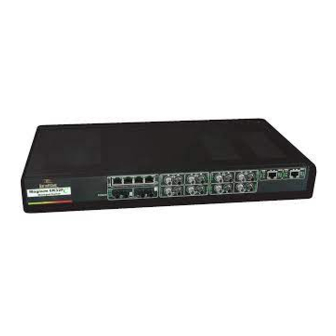
2.2.1a Magnum 6K32F / FR (Fan cooled) Managed Switch Chassis The high port density and fan cooled Magnum 6K32F / FR was designed for heavy duty Carrier class and Industrial applications that require high port density and secure devices which save in cost, rack space and run cool to provide long term reliability. -
Page 19: Eight-Port Sff Fiber Modules (6Kp8-Mtrj, 6Kp8-Mlc)
Ethernet requirements with cost-effective secure solutions. The Magnum 6K32F is also available in a Reverse model option, where the LEDs are on the front and the available ports along with the power supply area found on the rear side. -
Page 20: Eight-Port Copper Module, 6Kp8-Rj45 (Mdix)
Magnum 6K32F/FR/FC/FRC Managed Switch Installation and User Guide (05/08) when ON (half-duplex when OFF), and the blinking ACT LED indicates receiving Activity on the port. A fiber cable must be connected into a SFF port and the Link (LK) indicator for that port must be ON (indicating there is a powered-up device at the other end of the cable) in order for a LK LED to provide valid indications of operating conditions on that port. -
Page 21: Poe(Power Inside), Pi6Kp8-45Rj (Mdix), 8-Port 10/100Mb
Magnum 6K32F/FR/FC/FRC Managed Switch Installation and User Guide (05/08) 2.2.3a PoE(Power Inside), model PI6KP8-45RJ (MDIX), 8-port 10/100Mb The New PoE RJ-45 ports act similar to regular RJ-45 ports, except they have capability of providing power on each port to power up the PD devices, per the IEEE802.3af PoE standard. -
Page 22: Six-Port "4 + 2"Combo Modules Fiber St Or Sc
Magnum 6K32F/FR/FC/FRC Managed Switch Installation and User Guide (05/08) modules. Please check the ordering information Sec.1.2 for all the various P6K PoE modules option. The LEDs on 6KP8-RJ45- PoE module are slightly different compared to regular (non-PoE) RJ-45 modules as shown in Fig 2. When the PoE port is in use, the PoE LED is ON when connected properly to an 803.af compliant PD device on that port. -
Page 23: Four-Port 10 Mb Mm Fiber St Modules
3, 4, 7, 8 are not present. The default setup on the 10Mb fiber module is half- duplex, which allows the Magnum 6K32F Series Switch to connect to any 10Mb hub or media converter or almost any other device with a 10Mb fiber Ethernet port. User mode control per port through the MNS software is the same as the other 6K32F Series modules. -
Page 24: Packet Prioritization, 802.1P Qos
Magnum 6K32F/FR/FC/FRC Managed Switch Installation and User Guide (05/08) The 1000Mb Gigabit fiber-port modules on the Magnum 6K32F Series switches are normally set (factory default) to operate at AUTO mode for best fiber distance and performance. The 1000Mbps SC fiber-optic module on the Gigabit -SX and Gigabit-LX transceivers are compatible with the IEEE 802.3z Gigabit standards. -
Page 25: Managed Network Software 6K32F Series
Magnum 6K32F/FR/FC/FRC Managed Switch Installation and User Guide (05/08) When the Magnum 6K32F Series Switch detects that its free buffer queue space is low, the Switch sends industry standard (full-duplex only) PAUSE packets ou t to the devices sending packets to cause “flow control”. This tells the sending devices... -
Page 26: Features And Benefits
Modular design for port flexibility, in a 1U space-saving rack-mount package The 1U Magnum 6K32F Series chassis has 4 slots for port configurations. A family of 2, 4, 6 or 8 port modules allows the user to select the desired mix of port types and speeds. -
Page 27: Applications
The network administrator determines which ports and nodes are in which broadcast domains by setting membership profiles for each of them. The Magnum 6K32F’s VLAN capability can be configured in two types of virtual LANs; Port-based VLANs and Tag-based VLANs. - Page 28 Full-duplex future proof fiber media can easily connect long distance subnets and provide a stable secure network to all applications. The SNMP management capability of the Magnum 6K32F Series Switch helps create a database of all the network subnets to easily manage the network. Secure web-based management is also included, with authentication and encryption to keep out even determined trouble-makers.
- Page 29 Dual Source is especially useful in telecom central offices. The Magnum 6K32F Series with two Gigabit ports in a modular slot allows it to connect into a Gigabit mesh structure with an RSTP and S-Ring combination used in a no-single-point-of-failure self-healing LAN topology along with a ring of multiple 6K at the edge to allow the system to efficiently recover from a fault in the network.
- Page 30 The Magnum 6K32F Series with two slots filled with Gigabit modules and a robust management firmware with MNS-6K qualify this requirement efficiently. The New IGMP L2-Mode feature on Magnum 6K32F’s and loaded with management...
- Page 31 Magnum 6K32F/FR/FC/FRC Managed Switch Installation and User Guide (05/08) Equipped with IGMP-L2 mode enhanced features allow the Magnum 6K32F Series to meet the fastest growing application of video monitoring or video surveillance demand of industry and provide an economical and effective solution to meet that expectation.
-
Page 32: Installation
Locate an AC receptacle that is within six feet (2 meters) of the intended Magnum 6K32F site. The rugged metal case of the Magnum 6K32F Series will normally protect it from accidental damage in a lab or workplace setting. Maintain an open view of the front to visually monitor the status LEDs. -
Page 33: Connecting Ethernet Media
Magnum 6K32F/FR/FC/FRC Managed Switch Installation and User Guide (05/08) Connecting Ethernet Media The Magnum 6K32F Series Switches are specifically designed to support all standard Ethernet media types within a single Switch unit. This is accomplished by using a family of different port Modules which can be individually selected and configured per-port. -
Page 34: Connecting Fiber Optic Sc-Type, "Snap-In
Connecting Twisted Pair (RJ-45,CAT3, CAT5, Unshielded or Shielded) The RJ-45 ports of the Magnum 6K32F Series can be connected to the following two media types: 100BASE-TX and 10BASE-T. CAT 5 cables should be used when making 100BASE-TX connections. When the ports are used as 10BASE-T ports, CAT 3 may be used. -
Page 35: Connecting Twisted Pair (Cat-5E Or Better)
Connecting Twisted Pair (CAT-5e or better, Unshielded or Shielded) The RJ-45 1000BASE-TX Gigabit ports of the Magnum 6K32F Series can be connected via copper media with the following minimum specifications; 1000BASE-T, CAT-5e, or for better results, 100-ohm UTP shielded twisted pair (STP) balanced cable. -
Page 36: Gigabit Sfp (Small Form-Factor Pluggable) Transceivers
Magnum 6K32F/FR/FC/FRC Managed Switch Installation and User Guide (05/08) 3.2.6 Gigabit SFP (Small Form-factor Pluggable) Optical Transceivers The small form-factor pluggable (SFP) is a compact optical transceiver used in optical communications for both telecommunication and data communications applications. Due to its compact, hot pluggable characteristics, SFPs are becoming a very popular choice for various applications. -
Page 37: Power Budget Calculations 6K32F Series Pm's
Magnum 6K32F/FR/FC/FRC Managed Switch Installation and User Guide (05/08) The various SFPs transceivers supported by GarrettCom 6KQs D slot are- Module Model# Gigabit Gb Modules, fixed ports--SFP (Small Form Factor) 6KP2-2GSFP 2 SFP 6KP2-1GSFP1CU 1SFP 1 CU 6KP1-1SFP 1SFP 6KP1-1GCU... - Page 38 Magnum 6K32F/FR/FC/FRC Managed Switch Installation and User Guide (05/08) and the “Cable Loss” for 9/125 (Single-mode) is 0.25 dB/km(LXSC40) and the “Cable Loss” for 9/125 (Single-mode) is 0.2 dB/km (LXSC70) The following data has been collected from component manufacturer’s (Agilent’s and Lucent’) web sites and catalogs to provide guidance to network designers and installers.
-
Page 39: Rack-Mounting (For 19" Retma)6K32F & 6K32Fc's
Rack-mounting (for 19” RETMA racks) Magnum 6K32F & 6K32FC Installation of a Magnum 6K32F & 6K32FC Fiber Switch in a 19” rack is a simple procedure. The units are 1U (1.70”) high. When properly installed, the front- mounted LED status indicators should be in plain view and easy to read. -
Page 40: Rack-Mounting, Reverse Version Of The Magnum 6K32F's
With each bracket type, there are three different mounting options as shown in Fig. 3.3.2. The case of the Magnum 6K32F has mounting holes prepared for each of the mounting arrangements. Users may choose the mounting arrangement most suitable for their installation. -
Page 41: Alarm Contacts For Monitoring Internal Power Traps
See the Appendices of this manual for more details. Use an RFQ for other variations. 3.4.1 Alarm Contacts for monitoring internal power, and Software Traps The Alarm Contacts feature, optional on Magnum 6K32F Series, provides two Form C Normally Closed (NC) contacts to which the user can attach two sets of status monitoring wires at the green terminal block. -
Page 42: 6K32F Series Port Module (6Kpm) Installation
Magnum 6K32F/FR/FC/FRC Managed Switch Installation and User Guide (05/08) 6K32F Series Port Module (6KPM) Installation The Magnum 6K32F Series Switches are received from the factory with the customers required 6KPM modules installed. There may be situations where 6KPM cards need to be added or replaced. In cases where a 6KPM module needs to be added in the modular slots, the faceplate for an available front-mounted slot must be removed. - Page 43 Step 2. Remove Chassis Cover The Magnum 6K32F chassis are combined with top, bottom and module panel parts and assembled together with the help of 34 Philips-head screws. First Remove the side panel (2 screws located on the right side of chassis). Second, remove the module panel screws (total 16) as shown in the fig 3.5.1a.
-
Page 44: Installing 6Kpm Cards In The 6K32F Series
Magnum 6K32F/FR/FC/FRC Managed Switch Installation and User Guide (05/08) Looking down into the Magnum 6K32F Series unit, notice that there are individual PM installation spaces and female latch (white) connectors provided on the far right side of the main board along with four stand-off’s for 6KPM card position. (See Figure 3.5.1c). - Page 45 Magnum 6K32F/FR/FC/FRC Managed Switch Installation and User Guide (05/08) Step 3. The figure here illustrates the basic layout of an individual PM card. 6KPM card fits into the space provided on the main board over the grand-daughter Bd. a nd the male latched cream color connectors ( as shown in below fig.
-
Page 46: Removing 6Kpm Cards
Magnum 6K32F/FR/FC/FRC Managed Switch Installation and User Guide (05/08) NOTE:. When leaving 6KPM slots empty, always use a face plate (Magnum 6KM- BLNK) to cover the slot opening in the front panel. This will maintain proper cooling air flow, safety, and operation as required by FCC, CE, and other regulations. - Page 47 Magnum 6K32F/FR/FC/FRC Managed Switch Installation and User Guide (05/08) Step 2. Remove retaining screws placed on top for the 6KPM On the top of the daughter module there are seven retaining screws for each 6KPM card. These screws are used to secure a 6KPM card in position (see Figure 3.5.3a). Remove the...
-
Page 48: Connecting The Console Terminal To 6K32F Series
Connecting the Console Terminal to Magnum 6K32F Series Management) Use a DB-9 “null modem” cable to connect the Magnum 6K32F Series Console Port (the RS-232 port on the 6K32F Switch) to the your PC, so that your PC becomes the 6K32F’s Console Terminal. - Page 49 Magnum 6K32F/FR/FC/FRC Managed Switch Installation and User Guide (05/08) connect directly to the switch using a straight through cable. Note: For using Console port to configure the managed switch, a serial (Null-modem) female to female cable is required to communicate properly. The Null-Modem (DB-9)
-
Page 50: Operation
10 or 100Mb separate traffic domains for fiber ports to maximize bandwidth utilization and network performance. All ports can communicate to all other ports in a Magnum 6K32F, but local traffic on a port will not consume any of the bandwidth on any other port. -
Page 51: Status Leds
10 or 100Mb through software.. The Managed Magnum 6K32F Series Fast Ethernet copper ports can be set for either fixed 100Mb speed or N-way auto-negotiation per the IEEE802.3u standard. The selection is made via 6K-MNS software. -
Page 52: Flow-Control, Ieee 802.3X Standard
The Path Delay Value (PDV) bit-times must account for all devices and cable lengths within that domain. For Magnum 6K32F Series Fast Ethernet switched ports operating at 100Mb half-duplex, the bit time delay is 50BT. -
Page 53: 6K32F Series Managed Switch Port Modules
Refer to Chapter 5 for specific return procedures. 6KPM Module Description An important feature of the Magnum 6K32F Series is the use of one Port Module for flexible mixed-media connectivity to RJ-45 and fiber media in the www GarrettCom com... -
Page 54: 6Kp6-Rjmst Multi-Mode Fx-St "Twist Lock" Module
100BASE-FX network segments. When installed in a Magnum 6K32F Series Managed Switch, the copper port supports the standard distance 100m on each port and the fiber port supports fiber optic cable distances up the IEEE-standard 100Mb ps distance limits, i.e., typically 2km at full-... -
Page 55: 1B 6Kp4-F10St Multi-Mode Fx-St "Twist Lock" Module
Magnum 6K32F/FR/FC/FRC Managed Switch Installation and User Guide (05/08) connector functions as a fiber optic transceiver to support 10BASE-FX network segments. When installed in a Magnum 6K32F Series Managed Switch, the copper port supports the standard distance 100m on each port and the fiber port supports fiber optic cable distances up to the IEE E-standard 10Mbps distance limits, i.e., typically 2km at... -
Page 56: 6Kp6-Rjmsc Multi-Mode Fx-Sc "Snap-In" Module
Magnum 6K32F/FR/FC/FRC Managed Switch Installation and User Guide (05/08) provide a convenient way for the half duplex hub to connect to the switch through 10Mb fiber ports. Whereas the 100Mb ST module allows it to connect the 100Mb demand of the Switch devices. -
Page 57: 6Kp6-Rjsscl Fx-Sc-Type, "Snap-In" Connector
6K32F Series Switch supporting four Copper and two single-m ode fiber network segments. The 6KP6-RJSSC, when installed in a Magnum 6K32F Series Switch operate on copper at the 100m distance. The Fiber is single -mode and cable lengths can be as much as 25+ Km (see Power Budget, Section 4.5) -
Page 58: 6Kp8-Mtrjj Small-Form-Factor
This combo module provides more flexibility to the user to conn ect their gacy 10 Mb fiber as well as 100Mb to the Magnum 6K32F Series Switch. When installed in a Magnum 6K32F Series Switch, the 100Mb MTRJ connector supports fiber optic cable distances up to the IEEE-standard 100Mbps distance limits, i.e., typically 2km at full-duplex and 412m at half-duplex. -
Page 59: 6Kp8-45Mt Mtrj Small-Form-Factor
Magnum 6K32F/FR/FC/FRC Managed Switch Installation and User Guide (05/08) the same as the ST and SC-types. It has the same LEDs per port indicating port activity ACT), Link (LK), and FDX or HDX operation 6KP8-45MT, 4@ 10/100Mbps RJ-45 and 4@100Mb multi-mode 5.2.6... -
Page 60: 6Kp8-45Lc 10/100 Mbps Rj-45 Connector
6KP8-45LC is equipped w 4 10/100 RJ-45 ports an LC( Small form factor) multi-mode fiber ports. When installed in a Magnum 6K32F Series Switch, it supports the standard distances as er mentioned on 5.2.8. and the LEDs also act similarly as mentioned above. -
Page 61: 10A. Poe (Power Pass-Through)P6Kp8V-Rj45 (Mdix)
Magnum 6K32F/FR/FC/FRC Managed Switch Installation and User Guide (05/08) Each port has an Activity (ACT) LED indicating packets being received, a Link (LK) LED that indicates proper connectivity with the remote device when lit, a FDX/HDX LED to indicate full-duplex mode when lit (or half-duplex when off), and a “10/100”... -
Page 62: 10B. Poe(Power Inside), Model Pi6Kp8-45Rj (Mdix)
Magnum 6K32F/FR/FC/FRC Managed Switch Installation and User Guide (05/08) informati on Sec.1.2 for all the various P6K PoE modules option. The LEDs on 6KP8-RJ45- PoE modules are slightly different compared to regular (non-PoE) RJ-45 modules as shown in Fig 2. When the PoE port is in use, PoE LED is ON when connected p roperly to an 803.af compliant PD device on that port. -
Page 63: 6Kp8-45-2Mt Mtrj Small-Form-Factor
6KP8-45-2MT is equipped with six 10/100 RJ-45 ports and two 100Mb MTRJ fiber ports. When installed in a Magnum 6K32F Series Switch, it supports the standard distances as mentioned on 5.2.3. and the LEDs also act similarly. www GarrettCom com... -
Page 64: 11A 6Kp8-45-2Lc Single-Mode Fx , Lc Small-Form-Factor
The 6KP8-45- 2SLC is equipped with 6 10/10 RJ-45 ports and 2 Single-mode fiber ports. When installed in a Magnum 6K32F Series Switch, it supports the stan dard distances as mentioned on 5.2.4. and the LEDs also act similarly. -
Page 65: Gbpm-2Otx (Two Gigabit Option)
Magnum 6K32F/FR/FC/FRC Managed Switch Installation and User Guide (05/08) 5.2.12a GBPM-2OTX (Two Gigabit option) The Magnum 6K32-Series offered a wide selection of Gigabit speed with multiple choice of copper or Fiber or mix for the modular slot via GBPM-2OTX (2 x Giga module). -
Page 66: 6Km-Blnk
Please follow the suggestions listed below prior to contacting your supplier. However, if you are unsure of the procedures described in this section or if the Magnum 6K32F Series Switch is not performing as expected, do not attempt to repair the unit;... -
Page 67: Before Calling For Assistance
(About 90% of network downtime can be attributed to wiring and connector problems.) Make sure that an AC power cord is properly attached to each Magnum 6K32F Series Switch unit. Be certain that each AC power cord is plugged into a functioning electrical outlet. -
Page 68: Return Material Authorization (Rma) Procedure
Date of installation Failure symptoms, including a full description of the problem. GarrettCom will carefully test and evaluate all returned products, will repair products that are under warranty at no charge, and will return the warranty-repaired units to the sender with shipping charges prepaid (see Warranty Information, Appendix A, for complete details). -
Page 69: Shipping And Packaging Information
Magnum 6K32F/FR/FC/FRC Managed Switch In tallat ion and User Guide (05/08) Shipping and Packaging Information Should you need to ship the unit back to GarrettCom, please follow these instructions: Package the unit carefully. It is recommended that you use the original container if available. -
Page 70: Appendix B : Internal Dc Power Supply Options
Power Consumption: Same as for AC models (see Section 1.1) With the exception of the power supply, all specifications and functions of Magnum 6K32F Series Switch -48VDC, 24VDC and 125VDC models are identical to those listed in the main manual. - Page 71 6K32F Series is located on the rear of the unit and is equipped with three (3) screw- down lead posts. It is similar for 24VDC and 125VDC options on Magnum 6K32F Series. The leads are identified as negative (-), positive (+), and chassis ground (GND).
- Page 72 48V or –48V supply must be connected to the post labeled “+”. An ON-OFF manual switch is optional for DC power. This can be used to cut off power connections and as a RESET for the Magnum 6K32F Series Switch. B4.1 UL Requirements for DC-powered units Minimum 18AWG cable for connection to a Centralized DC power source.
-
Page 73: Appendix C: Internal Dc Dual-Source Power Option
Two separate sources, each at 88 - 150 VDC With the exception of the dual DC input power connections and the power supply, all specifications and configuration options for the Magnum 6K32F -48VDC, 24VDC and 125VDC models with this Dual-Source option are identical to those listed in the Magnum 6K32F Series Fiber Switches Installation and User Guide, including Appendix B “Internal DC Power Supply Option”... - Page 74 Magnum 6K32F/FR/FC/FRC Managed Switch Installation and User Guide (05/08) C3.0 DUAL-SOURCE OPTION, THEORY OF OPERATION The Dual-Source DC power option is designed using diodes inside of the chassis on each DC power input line. A diode is placed in each of the four input lines (behind the four external power connection terminals) so that power from an external source can only flow into the unit.
- Page 75 Switch’s power terminals, positive (+) and negative (-) screws. Ensure that each lead is securely tightened. The 24VDC and 125VDC terminal block on Magnum 6K32F Series is similar to that described in the –48VDC information above. C5.1 UL Requirements The following must be adhered to in order to conform to UL requirements: Minimum 18 AWG cable for connection to a Centralized DC power source.
Need help?
Do you have a question about the Magnum 6K32F and is the answer not in the manual?
Questions and answers