Table of Contents
Advertisement
Quick Links
Advertisement
Table of Contents

Related Manuals for GarrettCom Magnum 6K32


Summary of Contents for GarrettCom Magnum 6K32
-
Page 1: Managed Switch
Corporate Headquarters GarrettCom, Inc. Magnum 6K32 47823 Westinghouse Drive Fremont, CA 94539 Managed Switch Phone (510) 438-9071 Fax (510) 438-9072 Website: http://www.GarrettCom.com email support@garrettcom.com Hardware Installation and User Guide www GarrettCom com www GarrettCom com... - Page 2 If problems are experienced with Magnum 6K32 Switch products, consult Section 6, Troubleshooting, of this User Guide. Copyright © 2005 GarrettCom, Inc. All rights reserved. No part of this publication may be reproduced without prior written permission from GarrettCom, Inc.
- Page 3 Magnum 6K32 Managed Switch Installation and User Guide (05/05) Contacting GarrettCom, Inc Please use the mailing address, phone and fax numbers and email address listed GarrettCom, Inc. below: 213 Hammond Ave. Fremont, CA 94539 Phone (510) 438-9071 Fax (510) 438-9072 Website: http://www.GarrettCom.com...
-
Page 4: Table Of Contents
Technical Specifications... 1 Ordering Information ... 4 INTRODUCTION... 6 Inspecting the Package and Product... 6 Product Description - Magnum 6K32 Managed Switch ... 7 2.2.1 Magnum 6K32 and 6K32R chassis ... 8 2.2.2 Eight-port SFF fiber modules 100Mb fiber... 9 2.2.3... - Page 5 APPENDIX C: INTERNAL DC DUAL-SOURCE POWER OPTION ... 57 Revisions Rev A 05/05 : Minor updates, Auto-Cross(MDIX) Rev A 02/05 : Minor updates and tweak on LC connector diagram Rev A 08/04 : This revision is the initial release of the 6K32 manual. www GarrettCom com...
-
Page 6: Magnum 6K32 Managed Switch Installation And User Guide
ETHERNET CONNECTIVITY PRODUCTS "DESIGNED AND MANUFACTURED IN THE USA" OVERVIEW GarrettCom, Inc. offers the premium-quality Magnum™ line of Ethernet LAN connectivity products with industry-standard functionality and built-in fiber configurability. Magnum products are designed for use in demanding Carrier Class, Industrial Grade and OEM applications where reliability is a primary consideration. -
Page 7: Specifications
Magnum 6K32 Managed Switch Installation and User Guide (02/05) SPECIFICATIONS Technical Specifications Performance Filtering / Forwarding Rate: Ethernet:14,880 pps Fast Ethernet: 148,800 pps Gigabit Ethernet: 1,488,000 pps Switching Processing Type: Store and Forward with IEEE 802.3x full- duplex flow -control, non-blocking... - Page 8 Magnum 6K32 Managed Switch Installation and User Guide (02/05) Fiber connector types supported: ST-type (twist-lock) SC-type (snap-in) MTRJ-type Small Form Factor (SFF) LC-type Small Form Factor (SFF) GBIC modules LEDs: Per Port LK: Steady ON when media link is operational...
- Page 9 NEBS L3 and ETSI Compliant for Carrier Central Offices IEEE P1613 Environmental Standard for Electric Power Substations. IEC61850 EMC and Operating Conditions Class C for Power Substations Warranty: Three years, return to factory For a Configuration Guide, see the GarrettCom web site at http://www.garrettcom.com/techsupport/insertion_guides/6k32cg.pdf mktg@GarrettCom.com Email for additional details.
-
Page 10: Ordering Information
Magnum 6K32R-125VDC: Same as 6K32R except the power input is 125VDC Configuration Options: Each Magnum 6K32 and 6K32R base unit has one port module slot to be configured with one of the port modules listed below: Magnum 6K32 Port Modules... - Page 11 CONSOLE USB Console attachment cable, serial to USB, cable with one DB9 for the managed Switch and a USB interface for the USB connector to a PC. See also the “Configuration Guide” for the 6K32 on the GarrettCom web site at http://www.garrettcom.com/techsupport/insertion_guides/6k32cg.pdf.
-
Page 12: Introduction
Inspect the contents of this package for any signs of damage and ensure that the items listed below are included. This package should contain: Magnum 6K32 Managed Switch, base unit (configured with user-selected port module option in modular slot) AC Power Cord (U.S. and other 115 VAC only) Set of metal “Ears”... -
Page 13: Product Description - Magnum 6K32 Managed Switch
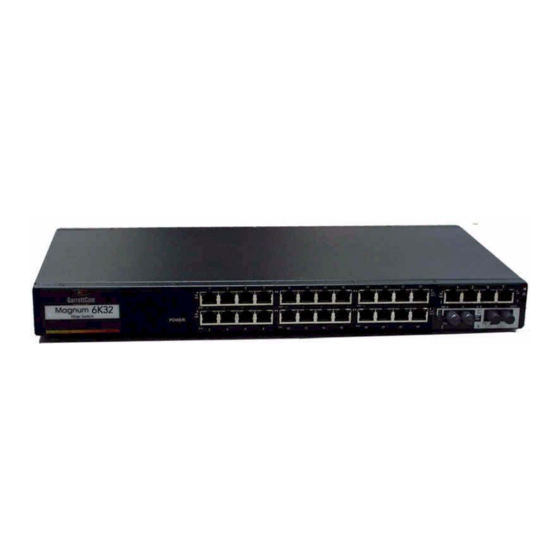
Installation and User Guide (02/05) Product Description - Magnum 6K32 Managed Switch The Magnum 6K32 Managed Switch provides high port density, with up to 32 ports in a 1U rack-mount package. It is used to boost the performance of large Ethernet LANs, typically serving as a “backbone”... -
Page 14: Magnum 6K32 And 6K32R Chassis
Gb module that accepts GBICs. The port types configurable using the modular slots allows the 6K32 to efficiently serve a large variety of applications, even those using some fiber media. The Magnum 6K32 port modules are normally factory installed, but may be changed or added in the field. -
Page 15: Eight-Port Sff Fiber Modules 100Mb Fiber
Using the 6K32’s MNS software, the user may select full- or half-duplex mode per-port through set-up of the software (See Magnum 6K32 MNS Software Manual) for the flexibility to adapt to any FDX or HDX type of Fast Ethernet devices). -
Page 16: Eight-Port Copper Module, 6K8-Rj45
RJ-45 port. MNS-6K Software allow to select 10Mb or 100Mb speed and full- or half-duplex mode per-port as per user requirement. (See Magnum MNS-6K Software Manual for details info). See Section 4.3 for Up-Link switch. 2.2.4 Six-Port “4 + 2”... -
Page 17: Four-Port 10 Mb Mm Fiber St Modules
10Mb fiber Ethernet port. User mode control per port through the MNS software is the same as the other 6K32 modules. The fiber ports support fiber cabling distances according to the 10BASE-FL standard, i.e., 2km distance for multi-mode fiber. -
Page 18: Gigabit (1000Mbps) Port Modules
Quality of Service means providing consistent predictable data delivery to users from datagram paths that go all across a network. As a LAN device, the Magnum 6K32 can do its part to prevent any QOS degradation while it is handling Ethernet traffic through its ports and buffers. -
Page 19: Frame Buffering And Flow Control
When the Magnum 6K32 Switch detects that its free buffer queue space is low, the Switch sends industry standard (full-duplex only) PAUSE packets out to the devices sending packets to cause “flow control”. -
Page 20: Managed Network Software (Mns-6K) For Magnum 6K32
2.2.9 Managed Network Software (MNS-6K) for Magnum 6K32 Magnum 6K32 Managed Switches are factory-loaded with licensed MNS-6K software. For additional information about MNS-6K, see the Magnum MNS-6K Software User guide in pdf format, a separate document normally accessed via the web- ftp://ftp.garrettcom.com/... -
Page 21: Features And Benefits
Modular design for port flexibility, in a 1U space-saving rack-mount package The 1U Magnum 6K32 chassis has 1 slot for port configurations. A family of 2, 4, 6 or 8 port modules allows the user to select the desired mix of port types and speeds. -
Page 22: Applications
Gb backbone services. The performance characteristic of the 6K32 Switches enables them to inter-connect a series of subnets (one subnet per 6K32 Switch port) in a LAN traffic center. The subnet connections may be via fiber or twisted pair cabling, 100Mbps or 10 Mbps speed, and full-or half-duplex mode. - Page 23 Full-duplex future proof fiber media can easily connect long distance subnets and provide a stable secure network to all applications. The SNMP management capability of the Magnum 6K32 Switch helps create a database of all the network subnets to easily manage the network. Secure web-based management is also included, with authentication and encryption to keep out even determined trouble-makers.
- Page 24 The -48VDC input power option with Dual Source is a useful option in telecom central offices. The Magnum 6K32 with two Gigabit ports in the modular slot allows it to connect into a Gb mesh structure with RSTP and S-Ring combo used in a no- single-point-of-failure self-healing LAN topology along with a ring of multiple 6K25s at the edge to efficiently recover from a fault in the network.
- Page 25 The figure below has Magnum 6K32’s and 6K25’s connected over the gigabit mesh structure for a high bandwidth secure redundant LAN setup.
-
Page 26: Installation
Ethernet media types. Locating Magnum 6K32 Switches The location of a Magnum 6K32 Switch is dependent on the physical layout of the network. Typically the Switch is placed in a central wiring location where groups of network devices need to be connected in order to communicate with each other. -
Page 27: Connecting Fiber Optic St-Type, "Twist-Lock
Connecting Fiber Optic ST-type, “twist-lock” The following procedure applies to installations using a PM with ST-type fiber connectors. This procedure applies to ports using a 6K32 module, MST-type port. Before connecting the fiber optic cable, remove the protective dust caps from the tips of the connectors on the PM. -
Page 28: Connecting Single-Mode Fiber Optic
3.2.4 Connecting Twisted Pair (RJ-45,CAT3, CAT5, Unshielded or Shielded) The RJ-45 ports of the Magnum 6K32 can be connected to the following two media types: 100BASE-TX and 10BASE-T. CAT 5 cables should be used when making 100BASE-TX connections. When the ports are used as 10BASE-T ports, CAT 3 may be used. -
Page 29: Table-Top Or Shelf Mounting
3.3.1 Rack-mounting (for 19” RETMA racks), regular Magnum 6K32s Installation of a Magnum 6K32 Fiber Switch in a 19” rack is a simple procedure. The units are 1U (1.70”) high. When properly installed, the front-mounted LED status indicators should be in plain view and easy to read. -
Page 30: 3.3.2 Rack-Mounting, Reverse Version Of The Magnum 6K32S
The bracket mounting holes in the sides of the Magnum 6K32 permits it to be mounted in various ways. The same holes fit all three types (19”, ETSI, 23”) of brackets. -
Page 31: Powering The Magnum 6K32 Managed Switch
With each bracket type, there are three different mounting options is shown in Fig. 3.3.2. The case of the Magnum 6K32 has mounting holes prepared for each of the mounting arrangements. Users may choose the mounting arrangement most suitable for their installation. -
Page 32: 6K32 Port Module (6Kpm) Installation
The AC or DC power input connection is in the same panel. A manual On-Off Switch for power to the unit is not available on 6K32 units with the Alarm Contacts option, as these two features occupy the same space in the case. - Page 33 Step 2. Remove Chassis Cover The Magnum 6K32 chassis are combined with top, bottom and front panel parts and assembled together with the help of 17 Philips-head screws. There are 5 screws located on the front-bottom and 3 at rear-top of the unit and one each on the front and rear sides.
- Page 34 Fig 3.5.1b: Pulling out the top coved from the chassis base Caution: Be careful not to disturb the power supply. Looking down into the Magnum 6K32 unit, notice that there are individual PM installation spaces and female latch (white) connectors provided on the far right side of main board along with four stand-off’s for 6KPM card position.
-
Page 35: Installing 6Kpm Cards In The Magnum 6K32
Placed Granddaughter board (as shown in fig. 3.5.2a and 3.5.2b) on the chassis built in stand off (female) provided at the front of the 6K32 Main Board and screw down tightly with the three 5/16 stand-off (male) on the top of the Granddaughter board The 5/16 stand off has been used to place the daughter board on the top of the granddaughter board and latch it securely. - Page 36 Once the latching connectors are aligned properly and the mounting holes are aligned with stand offs then press slowly and firmly with two fingers (as shown Securely latching up 6KPM Cards into a Magnum 6K32 www GarrettCom com Fig 3.5.2e Daughter Bd.
-
Page 37: Removing 6Kpm Cards
NOTE ( checking the speed, F/H, and activity status) 3.5.3 Removing 6KPM Cards To properly remove a 6KPM card from the 6K32 Managed Switch, follow the 3 steps below. Step 1. Remove chassis cover See procedures in Section 3.5.1 above. - Page 38 –{ failed to read register device type (offset 0x1600) on slot “A or B or C or D”}, whichever the slot has been used. 3. Always boot-up the Switch after any new module installation on modular slot to confirm the successful installation, before placing the chassis cover.
-
Page 39: Connecting The Console Terminal To Magnum 6K32
Connecting the Console Terminal to Magnum 6K32 (Management) Use a DB-9 “null modem” cable to connect the Magnum6K32 Console Port (the RS-232 port on the 6K32 Switch) to the your PC, so that your PC becomes the 6K32’s Console Terminal. -
Page 40: Operation
Switching Functionality A Magnum 6K32 provides switched connectivity at Ethernet wire-speed among all of its ports. The Magnum 6K32 supports10/100Mbs for copper media and 10 or 100Mb separate traffic domains for fiber ports to maximize bandwidth utilization and network performance. All ports can communicate to all other ports in a Magnum 6K32, but local traffic on a port will not consume any of the bandwidth on any other port. -
Page 41: Status Leds
In such cases, the 10/100 speed or the F/H mode may be affected, but auto-cross in the 6K32 Switches will still work. The auto-cross function can be disabled, if fixed the port at 10 or 100Mb through software.. - Page 42 Magnum 6K32 Managed Switch Installation and User Guide (02/05) The Managed Magnum 6K32 Fast Ethernet copper ports can be set for either fixed 100Mb speed or N-way auto-negotiation per the IEEE802.3u standard. The selection is made via 6K-MNS software. The factory default setting is for auto- negotiation.
-
Page 43: Flow-Control, Ieee 802.3X Standard
If the device at the other end is not an auto-negotiating device, the 6K32’s RJ-45 ports will try to detect its idle signal to determine 10 or 100 speed, and will default to half-duplex at that speed per the IEEE standard. -
Page 44: Power Budget Calculations For Magnum 6K32 Pm's
Magnum 6K32 Managed Switch Installation and User Guide (02/05) Power Budget Calculations for Magnum 6K32 PM’s with Fiber Media Receiver Sensitivity and Transmitter Power are the parameters necessary to compute the power budget. To calculate the power budget of different fiber media... -
Page 45: Magnum 6K32 Managed Switch Port Modules
Inspecting the Package and Product This section applies only to PMs shipped as separate items, i.e., 6K32 PMs not factory installed in a Magnum 6K32 modular slot. Examine the shipping container for obvious damage prior to installing a 6K32 PM;... -
Page 46: 6Kpm Module Description
Since the Magnum 6K32 Switches have dual-speed capability for copper ports, the 6 or 8-port interfaces are designed to support all standard Ethernet media types at 10 or 100Mps speed. Each 6K32 PM can provide two, four, six or eight ports for connecting Ethernet segments with its individual connector type and media. -
Page 47: 1A 6Kp6-Rj10St, "Twist Lock" Combo Module
The ST-connector functions as a fiber optic transceiver to support 10BASE-FX network segments. When installed in a Magnum 6K32 Managed Switch, the copper port supports the standard distance 100m on each port and the fiber port supports fiber optic cable distances up the IEEE-standard 10Mbps distance limits, i.e., typically 2km at full-duplex... -
Page 48: 1C 6Kp4-Flstfx, "Twist Lock" Module
100Mb fiber. The 10Mb ST-fiber ports allow the user to connect their legacy 10Mb network to the Magnum 6K32 switch. They also provide a convenient way for the half duplex hub to connect to the switch through 10Mb fiber ports. Whereas the 100Mb ST module allow to connect the 100Mb demand of Switch devices. -
Page 49: 6Kp6-Rjssc "Snap-In" Connector
ACTIVITY through combining copper and Fiber functions in one module of the 6K32 Switch supporting four Copper and two single-mode fiber network segments. The 6KP6-RJSSC, when installed in a Magnum 6K32 Switch operates on copper at the 100m distance. The Fiber is single-mode and cable lengths can be as much as 25+ Km (see Power Budget, Section 4.5) -
Page 50: 4A 6Kp6-Rj10St Fl-St-Type, "Twist-Lock" Connector
The Magnum 6KP6-RJ10ST is also a Combo module equipped with 4 dual speed copper ports and 2 multi-mode 10 Mb fiber ST-type connectors. It provides a combination of copper and Fiber functions in one module to the 6K32 Switches, supporting four Copper and two 10Mb of ST fiber network segments. -
Page 51: 6Kp8-Mtrj, Mtrj Small-Form-Factor
100Mb full-duplex, whereas the bottom two ports multi-mode ST-Fiber support 10Mb half-duplex. This combo module provides more flexibility to the user to connect their legacy 10Mb fiber as well as 100Mb to the Magnum 6K32 Switch. When installed in a Magnum 6K32 Switch, the 100Mb MTRJ connector supports fiber optic cable distances up to the IEEE-standard 100Mbps distance limits, i.e., typically 2km at full-duplex and 412m at half-duplex. -
Page 52: 6Kp8-45Mt, Mtrj Small-Form-Factor
LC connector “small-form- factor” used primarily in 100Mbps fiber-to- the-desktop links. When installed in a Magnum 6K32 Switch, it supports fiber optic cable distances up to the IEEE-standard 100Mbps distance limits, i.e., typically 2km at full-duplex and 412m at half-duplex. -
Page 53: 6Kp8-45Lc, Combo Factor And Rj-45 Connector
Small form factor) multi-mode fiber ports. ACTIVITY When installed in a Magnum 6K32 Switch, it supports the standard distances as per mentioned on 5.2.8. and the LEDs also acts similarly as mentioned above. 5.2.9 6KP8-RJ45 (Twisted Pair), 10/100Mb 8-Port The 6KP8-RJ45 module supports Ethernet twisted pair segments of any standard length. -
Page 54: 6Kp8-45-2Mt, Multi-Mode Fx , Mtrj Small-Form-Factor
ACTIVITY six 10/100 RJ-45 ports and two 100Mb MTRJ fiber ports. When installed in a Magnum 6K32 Switch, it supports the standard distances as mentioned on 5.2.3. and the LEDs also act similarly. 5.2.10a 6KP8-45-2LC, 6@ 10/100Mbps RJ-45 and 2@100Mb single-mode... -
Page 55: Gbic-Sxsc Gigabit Fiber(1000Mb), Multi-Mode Sc Connector
The 6KP8-45- 2SLC is equipped with 6 10/100 RJ-45 ports and 2 Single-mode fiber 10/10 ports. 10/100 When installed in a Magnum 6K32 Switch, it supports the standard LINK distances as mentioned on 5.2.4. ACTIVITY and the LEDs also act similarly. -
Page 56: Gbic-Lxsc Gigabit Fiber (1000Mb), Mm Sc Connector
All Magnum Ethernet products are designed to provide reliability and consistently high performance in all network environments. The installation of a Magnum 6K32 Switch is a straightforward procedure (see INSTALLATION, Section 3.0); the operation is also straightforward and is discussed in Section 4. -
Page 57: Before Calling For Assistance
However, if you are unsure of the procedures described in this section or if the Magnum 6K32 Switch is not performing as expected, do not attempt to repair the unit; instead contact your supplier for assistance or contact GarrettCom Customer Support. -
Page 58: Return Material Authorization (Rma) Procedure
All returns for repair must be accompanied by a Return Material Authorization (RMA) number. To obtain an RMA number, http://www.garrettcom.com/techsupport/RMA/rma.htm Or call GarrettCom Customer Service at (510) 438-9071 during business hours in California or email to support@garrettcom.com). When calling, please have the following information readily available: Name and phone number of your contact person. -
Page 59: Shipping And Packaging Information
Installation and User Guide (02/05) result in a customer (user) charge. Shipping and Packaging Information Should you need to ship the unit back to GarrettCom, please follow these instructions: Package the unit carefully. It is recommended that you use the original container if available. - Page 60 B3.0 APPLICATIONS FOR DC POWERED SWITCHES Magnum 6K32 Fiber Switches are easily installed in a variety of applications where -48VDC, 24VDC and 125VDC power is used as the primary power source. The- 48VDC, 24VDC and 125VDC power configuration provides an Ethernet networking solution utilizing a special power supply in a Managed Switch.
- Page 61 Magnum unit, beginning with ground. Ensure that each lead is securely tightened. Note: The GND should be hooked up first. The 6K32 unit has a floating ground, so the user may elect to Ground either + or = terminal to suit the customer’s use.
- Page 62 Magnum 6K32 Managed Switch Installation and User Guide (02/05) Operation of Magnum 6K32 Switches with the optional -48VDC, 24VDC and 125VDC power supply is identical to that of the standard AC-powered models. B6.0 ORDERING INFORMATION To order the optional -48VDC power supply factory installed, add a suffix of “- -48VDC”...
-
Page 63: Appendix C: Internal Dc Dual-Source Power Option
Magnum 6K32 -48VDC, 24VDC and 125VDC models with this Dual-Source option are identical to those listed in the Magnum 6K32 Fiber Switches Installation and User Guide, including Appendix B “Internal DC Power Supply Option”... - Page 64 125VDC dual source leads to the -48VDC, 24VDC 7 125VDC power terminal block on the Magnum 6Ks Switch (shown in Figure ) The -48VDC terminal block on the Magnum 6K32 Switch, as shown in Fig C5.0 is located on the right rear of the unit and is equipped with five (5) screw-down lead posts.
- Page 65 Magnum 6K32 Managed Switch Installation and User Guide (02/05) C5.1 UL Requirements The following must be adhered to in order to conform to UL requirements: Minimum 18 AWG cable for connection to a Centralized DC power source. Minimum 14 AWG cable for connection to earthing wiring.
Need help?
Do you have a question about the Magnum 6K32 and is the answer not in the manual?
Questions and answers