Table of Contents
Advertisement
Quick Links
4247-Z0
03plus
a
and Setup
CAUT
TION
Hazardous v
voltages are pr
sockets of th
he power recept
Carefully fol
llow all cleaning
materials an
nd solutions reco
High temper
rature; switch of
minutes for p
parts in this are
If the second
d tractor unit is
protector co
ver is closed. D
insert any ob
bject into the ge
This printer
has an optiona
installed on
any other stand
must suppor
rt the printer we
the print acti
ion vibration.
Unpa
cking Your
Printer
The foll
lowing items
are incl
uded in the
carton:
- Ribbo
on Cartridge
- Powe
r Cord
- CD fo
r drivers and
User's
s Guides
- Quick
Setup
Guide
Contac
t your point of p
purchase seller
Attentio
on! Always retai
n the original pr
shipme
ent of the printer
r.
Unpa
cking the pr
rinter
Movin
ng the printe
er to the fina
Attenti
on: The lifting
handles
are loc
cated forward
of the
center o
of gravity.
For goo
od printer balanc
ce,
each pe
erson should pla
ace one
hand in
n a gray lifting ha
andle
and the
e other hand und
der the
rear of
the printer.
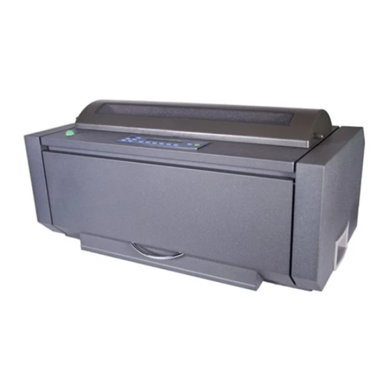
Locat
ting Printer
Parts
Front
t View
MAN1
10294‐R01
Qu
ick Install
ation
p Guide
resent. Do not
touch the pins
tacle.
g instructions,
using only
ommended.
ff the printer an
d allow at least
a to cool before
e handling.
not installed, m
make sure the ge
Do not touch In
side the printer
ears.
al printer pedest
tal. If the printe
d or surface, thi
s stand or surfa
eight of 33kg (73
3lb) and with sta
if any items are
missing.
rinter packaging
g in case of any
al location
R
Rear View
s or
C
hoosing a s
the
Co
onsider the f
wh
hen you choose
yo
our printer:
t 20
-T
The distance bet
an
nd the host com
ex
xceed the length
ca
able.
ear
-T
The location m
r or
ho
orizontal and sta
-Y
Your
printer
ex
xposed
r is
ex
xtreme
heat,
ace
hu
umidity
and
Sp
pecifications"
Gu
uide you find o
–
You need a
co
ompatible with
pr
rinter's power co
-F
For best continuo
sta
acking, the form
N
ominal AC i
Nominal
Voltage
1
00–240Vac
R
Removing th
1.
Open the tracto
shipping locks,
the lock swith th
2.
Open the upper
head, remove it
In
nstalling the
W
We recommend t
ins
stall the ribbon c
1.
Remove the rib
guide, snap ar
pins.
2.T
Turn the ribbon
any slack in th
place of ribbon
3.
Open the top co
cover.
4.
Slide the print h
5.A
Align the cartrid
right cartridge s
6.
Position the ribb
perpendicular to
7.T
Turn the ribbon
8.
Position the sn
assembly. Pus
until it snaps int
9.A
Align the ribbon
cartridge with t
cartridge down
10
0.Turn the ribbo
take up any sla
and forth to en
ribbon.
11
1.If the ribbon
installed the rib
1
suitable loca
ation
stacked o
following point
ts
surface be
e the location fo
or
printer. F
parking, th
tween the printe
er
mputer must no
ot
must alwa
h of the interfac
ce
base of the
Area outsid
Width: 20c
must be sturdy
y,
Depth:100
able.
Height:80c
must
not
b
be
to
direct
d
sunligh
ht,
cold,
dust
o
or
(se
ee
"Printe
er
in
the
User'
's
n the CD-Rom
).
a power outle
et
the plug of th
he
ord.
ous forms
ms should be
input power
r requiremen
Voltage Range
e
Amps/W
90–264Vac
2.9–1.3
e Shipment
Locks
or area cover an
nd make sure th
including the 2
2 knurled shipp
he packing mate
erial.
r printer cover. I
If there is a wire
t.
Ribbon Ca
rtridge
that you use an
n approved origi
cartridge, follow
w these steps:
bon cartridge fro
rom the package
rm, ribbon adva
ance knob, an
advance knob
in the direction
e ribbon. If the
e ribbon does n
purchase to rep
place the ribbon
over using the s
small handles o
head to the cent
ter of the printer
dge pins with the
e locking groove
supports.
bon guide over t
the print head,
o the print head
d.
advance knob
to take up any s
nap arm with th
he small lever
h the snap arm
m down onto th
to place.
n mounting pins
on the left and
the slots in the
e cartridge supp
into place.
n advance knob
b again in the di
ack in the ribbo
on, as you slide
nsure that the rib
bbon guide runs
is not running
g freely, or to
bon cartridge co
orrectly, ensure
n the floor o
r on a
elow the base
of the
or successful
forms
he input forms
s stack
ays be lower th
han the
e printer.
de the printer:
cm (7.9in.) each
h side
0cm 39.4in.) eac
ch side
cm (31.5in.)
nts
atts
Phas
se/Hz
3A
Sin
ngle
50-6
60Hz
at you remove a
all
ping lock screw
ws. Store
e tie around the
print
nal ribbon cartr
ridge. To
e. Locate the rib
bbon
d the ribbon m
mounting
of the arrow to
take up
not move, conta
act your
n cartridge.
one it her side o
of the top
r.
es on the left an
nd
holding it
slack in the ribb
bon.
up onto the rib
bbon lift
he ribbon lift as
ssembly
right side of the
e ribbon
ports. Snap the
e ribbon
irection of the a
rrow to
the print head b
back
s freely along th
he
ensure that yo
ou have
e that:
4247Z03Plu
us‐QSG
Advertisement
Table of Contents

Related Manuals for Compuprint 4247-Z03 Plus


Summary of Contents for Compuprint 4247-Z03 Plus
- Page 1 4247-Z0 03plus ick Install ation and Setup p Guide CAUT TION Hazardous v voltages are pr resent. Do not touch the pins s or sockets of th he power recept tacle. hoosing a s suitable loca ation...
-
Page 2: Host Computer Connection
a.The left and right ribbon mounting pins are securely snapped of the printer. into the cartridge supports. 3.Unlock the tractors by moving the sprocket levers up. Slide the left b.There are not wists or folds in the ribbon. tractor to the left. c.The ribbon is not catching on the print head. - Page 3 level of the menu. make and save printer configuration setting changes ENTER Installing the optional second tractor The Enter function is available when the Configuration Menu or Operator Print Tests Menu is displayed. Pressing ENTER selects the A second optional tractor is available for your printer. This tractor may displayed option.
- Page 4 becaus se they may cau use discoloration n or scratching. 3. Reload d forms onto the tract tor. 4. Close t the top cover. Attenti on: Do not allow w any staples, p paper clips, or s small metal piec 5.
- Page 5 press PARK/PATH Action 1. (see “Printer Specifications” in the User’s Guide). If you had just pressed PARK/PATH with the 091 FANFOLD Print quality and ribbon problems before tearing off the forms. PARK... message, proceed with Corrective Action 2. Problem: Unreadable characters Corrective Action 1 1.
- Page 6 9. Reload the forms. Detailed information on the Configuration of the Printer and not reported in this Quick Guide can be found in the User’s Guide present in the CD and also in the download link of the website: www.compuprint.com MAN10294‐R01 6 ...
Need help?
Do you have a question about the 4247-Z03 Plus and is the answer not in the manual?
Questions and answers