
Related Manuals for Compuprint L03


Summary of Contents for Compuprint L03
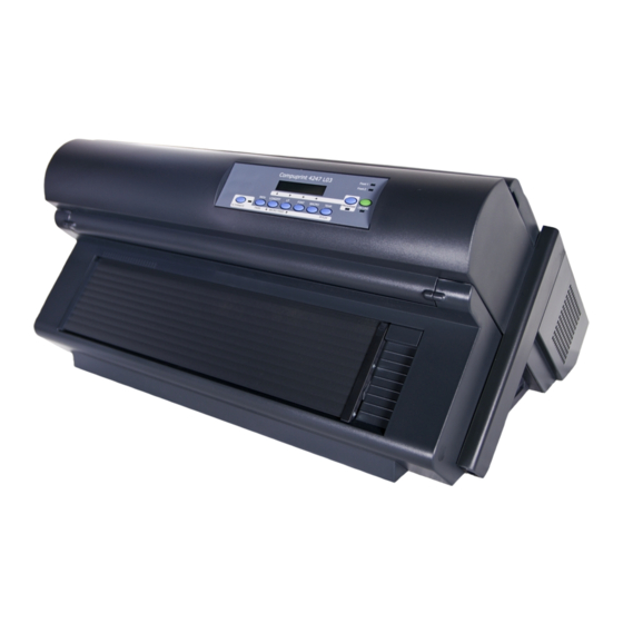
- Page 1 Compuprint 4247 Serial Matrix Printers Compuprint 4247 Model L03 Printer: User's Guide MAN10295.00.00...
- Page 2 Before using this information and the product it supports, read the information in “Notices” on page 127. First edition (October 2011) This edition applies to the Compuprint 4247 L03 printer and to all subsequent releases and modifications until otherwise indicated in new edition.
-
Page 3: Table Of Contents
Contents Figures ....v Entering the Printer Setups . . 29 Moving within the Printer Setups . . 29 Leaving the Printer Setups . . 29 Tables . - Page 4 User's Guide...
-
Page 5: Figures
Figures 4247 Printer: Front and Rear Views . Opening the Push tractor cover. . . 89 Printer Dimensions . Sliding the left sprocket to the first printing Removing the Shipment Locks from the Printer 6 column. . . 89 The Operator Panel . Opening the left and right sprocket covers. - Page 6 User's Guide...
-
Page 7: Tables
Tables ON LINE Key. . 25 Interface Type . . 48 PROGRAM Key . . 26 Interface Type . . 50 MACRO Key . . 26 Interface Type . . 53 FONT Key . . 26 Fanfold Paper . . 87 LF Key . - Page 8 viii User's Guide...
-
Page 9: Safety And Environmental Notices
Safety and environmental notices Safety notices There are two levels of safety notices: Danger and Cautions. Danger hazard level The word Danger indicates the presence of a hazard that has the potential of causing death or serious personal injury. Most DANGER notices are numbered <1-1>, <1-2>, and so forth where they appear in the text of this manual. -
Page 10: Safety Precautions
Safety precautions Never remove any printer cover except to install a printer accessory as expressly described in this manual. The following areas of the printer should be covered for safety reasons: Small Rear Cover Large Rear Cover Attention: The above openings must always be protected with their covers. Do not touch inside and do not insert any object into these openings or into the gears. -
Page 11: Electrical Safety And Portable Power Strip Receptacles
Electrical safety and portable power strip receptacles Extension cords DANGER DANGER<1-1> Do not use an extension power-cord. The customer must supply the correct electrical outlet which must meet the requirements stated under “Printer Specifications” in the User's Guide. Portable power strip receptacles (temporary power taps) Portable power strip receptacles (referred to as “temporary power taps”... - Page 12 User's Guide...
-
Page 13: Chapter 1. Getting To Know Your Printer
Chapter 1. Getting to Know Your Printer The 4247 L03 has the following features: v 24 Needle Print Head v 136 columns @ 10 cpi v Draft printing at 720 cps, Best Draft at 400 cps, NLQ at 260 cps, and LQ printing at 133 cps ®... -
Page 14: Unpacking Your Printer
Unpacking Your Printer The following items are included in the box: Contact your point of purchase seller if any items are missing. The Controller Board includes the printer software program (firmware) and the interface connectors to the host system. User's Guide... -
Page 15: Printer Parts
Printer Parts Figure 1. 4247 Printer: Front and Rear Views Chapter 1. Getting to Know Your Printer... - Page 16 User's Guide...
-
Page 17: Chapter 2. Setting Up Your Printer
Chapter 2. Setting Up Your Printer This section contains instructions for setting up your printer. Choosing a Suitable Location CAUTION: The 4247 printer weighs 21 kg (46 lbs). Two persons are required to lift Consider the following points when you choose the location for your printer: v The distance between the printer and the host computer must not exceed the length of the interface cable;... -
Page 18: Printer Assembly
Printer Assembly This sections describes how to assemble the printer. Removing the Shipment Locks Open all the printer covers and make sure that you remove all the shipment locks from the printer. Figure 3. Removing the Shipment Locks from the Printer The following sections describe how to install the Operator Panel Overlay, the ribbon cartridge, and the Controller Board. -
Page 19: Installing The Ribbon Cartridge
Installing the Ribbon Cartridge 1. Find the ribbon cartridge among the accessories. Ribbon Guide Ribbon Winding Knob Cartridge Pins Figure 5. The Ribbon Cartridge 2. Open the top cover using the small handles on either side of the top cover. Figure 6. -
Page 20: Aligning The Right And Left Cartridge Pins With The Printer Locking Points
3. Slide the print head to the center of the printer. Before installing the ribbon cartridge turn the ribbon-winding knob in the arrow direction (located on the cartridge) to take up slack in the ribbon. Cartridge Pins Ribbon Winding Knob Figure 7. -
Page 21: Turn The Ribbon-Winding Knob In The Arrow Direction
5. Slide and insert the ribbon guide between the print head and the ribbon guide mask holding it perpendicular to the print head. Make sure that the ribbon is inserted correctly between the print head and the Ribbon Guide mask. Figure 9. - Page 22 If the used ribbon cartridge needs to be replaced, see “Replacing the Ribbon Cartridge” on page 97. User's Guide...
-
Page 23: Installing The Controller Board
Installing the Controller Board The 4247 printer arrived with the Controller Board that you ordered. You must install the Controller Board (received with the printer) into the proper slot in the back of the printer before it can be used. Handling the Controller Board Attention: Do not remove the Controller Board from the protective package until instructed to do so. -
Page 24: Removing The Two Screws On The Metal Plate
Figure 11. Removing the two screws on the metal plate. 3. Use the information under “Handling the Controller Board” on page 11 as you remove the Controller Board from its shipping box and from the protective package. User's Guide... -
Page 25: Sliding The Board In The Slot
4. Align the left and right sides of the Controller Board with the guides in the printer and slide it into the slot. Figure 12. Sliding the board in the slot. 5. Gently push the Controller Board into the printer until it is seated in the connector inside the printer. -
Page 26: Host Computer Connection
Host Computer Connection This printer can be connected to your host computer with the interfaces available on the Controller Board you have found in the printer box and installed on the rear of the printer. There are two types of Controller Boards: 1. -
Page 27: Power Connection
Power Connection DANGER <1-11> Your country may require an approved power cord and plug. Ensure that you have the correct power cord and plug. Use this cord and plug only with an approved, correctly-installed power receptacle. 1. Make sure the power outlet is near the printer location and easily accessible. 2. - Page 28 3. Insert the power cable plug into the printer connector and the other power cable end into a convenient outlet. Figure 15. Inserting the power cable User's Guide...
-
Page 29: Power Switch In The I Position (On)
4. If you need to turn the printer on, press the power switch in the I position (ON). Figure 16. Power switch in the I position (ON) Attention: If, for any reason, the Controller Board was not correctly installed in the printer, the printer will not work and the following audio/visual symptoms will occur: v The buzzer sounds continuously... -
Page 30: Selecting The Display Language
Selecting the Display Language The display messages for this printer can be displayed in eleven different languages (the default language is English). To select the language you want, proceed as follows: 1. Press the PROGRAM key and keep it pressed while powering on the printer until the following message is displayed: RELEASE KEY 2. -
Page 31: Chapter 3. Configuring The Printer
Chapter 3. Configuring the Printer Operator Panel Presentation The operator panel enables you to perform many of the printer functions including paper path selections, font selection and the printer setup. Figure 17. Operator Panel Display Messages The printer display is used to indicate the printer status or to request an user intervention. - Page 32 User's Guide...
-
Page 33: Load Front1 Indicator
where: OFF LINE Indicates the printer status. ON LINE M1, M2, M3, M4 Indicate which of the four User Macros is currently used. v When there is no paper loaded and the printer is off line (ON LINE indicator unlit): Load Front1 Current Paper Path Figure 20. - Page 34 COVER OPEN When the printer cover is not closed correctly, the buzzer CLOSE COVER sounds and the display shows alternately these two messages. Close the printer cover. EJECTING The printer is ejecting the paper out of the printer. INITIALIZING LAN This message is displayed when the LAN is reset (only if the LAN interface board is installed).
- Page 35 For the error messages see “Error Handling” on page 100 later in this manual. Chapter 3. Configuring the Printer...
-
Page 36: Indicators
Indicators Lit when the printer can receive and print data (printer online). Blinks when there is data in the buffer and the printer is offline. ON LINE Unlit when the printer is disabled and the buffer does not contain any data, or during the initialization, setup or tests. Blinks when one of the printer setup procedures has been selected: Program Configuration or Power-On Configuration. -
Page 37: Function Keys
Function Keys Pressing the function keys it is possible to activate the functions indicated by the word or symbol signed near the key. Each key may have different functions, according to the selected function modes: Normal, Alternate or Program. Figure 22. Function Keys Normal Function The normal function of the keys is written above the keys and does not require any previous action... -
Page 38: Program Key
Scrolls the parameters of the functions or macros backwards. Function Note: If the selected emulation for the 4247-L03 printer is Epson LQ1600K, and the DBCS feature is installed, the FONT Key has the following additional options for DBCS fonts: Draft, Best Draft, NLQ, and LQ. -
Page 39: Load/Ff Key
LOAD/FF Key Table 6. LOAD/FF Key LOAD/FF Normal Executes a Form Feed (FF): when paper is loaded into the Function printer, it advances to the following page; if no paper is loaded, it is positioned for printing. MICRO Alternate Moves the paper backward in microsteps. Keeping the key FEED Function pressed the paper is moved continuously at increasing... -
Page 40: Key Combinations
Key Combinations Table 10. PATH/PARK Key ONLINE + MACRO + Normal Lock or unlock the access to the printer ALTERNATE Function setups. See later “How to Lock/Unlock the Printer Setups” on page 81 section. User's Guide... -
Page 41: Printer Setups
Printer Setups The main printer setup parameters can be selected via the operator panel. The setup parameters are divided into two printer setups, the Power-On Configuration, that allows a complete configuration at installation time according to the hardware and the emulation types, and the Program Setup, that allows you to set the functions that are the most useful in your daily job. -
Page 42: Power-On Configuration
2. Press and hold the PROGRAM key pressed while powering on the printer until the RELEASE KEY message is displayed. As soon as the PROGRAM key gets released, the following message will be displayed: 4247 L03 then, PRINT OUT? NO... - Page 43 v Bar code printing direction v Graphics printing speed v Paper path at power on, v Language of the display messages v Tear-off position adjustment PRINT OUT? NO PRINT OUT? YES EMUL OPTIONS PRINT OUT? The Setup is not printed. PRINT OUT? The printer setup is printed showing the currently selected values.
-
Page 44: Emulation Options Menu
Emulation Options This setup defines the available options according to the selected emulation and is structured as follows: Emulation ANSI EPSON LQ IBM ... ANSI Option IBM/EPSON Char. Set ... Char. Set ... CH Tab Code ... Nation ... Nation ... Auto CR ... - Page 45 The printer uses the EPSON LQ Series emulation. EPS 1600K The printer uses the EPSON LQ1600K emulation. Note: The EPS 1600K is only available on the 4247-L03 printer with the DBCS feature installed. It is the default emulation. IBM XL24 The printer uses the IBM Proprinter XL24 emulation.
- Page 46 EPSON National Character sets: CHAR. SET CS2 NATION CP437 NATION ... NATION LATIN A1 AUTO CR YES The following national character sets are available: CP 437 CP437 G 96GREEK CP850 CP851 CP 852 CP 853 CP 855 CP 857 CP 858 CP 860 CP 862 CP 863...
- Page 47 CR Code Behavior: NATION xxx AUTO CR NO AUTO CR YES AUTO LF NO AUTO CR No automatic carriage return is performed after a LF, VT or ESCJ code. Default value in IBM emulation. AUTO CR The printer performs an automatic carriage return after a LF, VT or ESCJ code.
- Page 48 BAR CODE Commands: 20 CPI IBM or AUTO LF NATIVE ALTER EMULULATION NATIVE Barcode is activated in Native mode. ALTER Barcode is activated in ANSI mode. Selecting ANSI Options These items appear only if the ANSI emulation has been selected. ANSI Character Sets: ANSI GUARD BAR NO...
- Page 49 ANSI National Sets: CH.TAB.. CODE437 NATION USA NATION ... NATION CYRILLIC RIS ENABLE YES The following national sets are available: GERMANYFRANCE FRANCE FREN/ DUTCH ITALY CANA SPAIN DAN/ DAN/ DAN/ DAN/ SWE/FIN SWE/FIN SWE/FIN NOR A NOR B NOR C NOR D SWE/FIN SWISS...
- Page 50 Auto Carriage Return: SI/SO CTL NO AUTO CR YES AUTO CR NO PRIME ON DEL NO If the printer receives a command (LF) from the host to perform a line feed, the printer will (YES) or will not (NO) append a carriage return based upon your selection.
- Page 51 This setting defines the vertical expansion from the baseline up (YES) or from the top line down (NO). Chapter 3. Configuring the Printer...
- Page 52 ALT Graphics: EXPAND UP YES ALT GRAPHICS YES ALT GRAPHICS NO 8 BIT CTRL NO If NO is selected, the 6-bit graphics horizontal densities are multiplies of 72. If YES is selected, the 6-bit graphics horizontal densities are multiplies of 60. 8-bit Control: ALT GRAPHICS NO 8 BIT CTRL YES...
- Page 53 Superscript/Subscript Character Enable: ENQ CODE NO S/SUB SCRIPT YES S/SUB SCRIPT NO ESC+CTR CODE NO The printer will (YES) or will not (NO) respond to ESC [2 m and ESC [3 m commands. ESC+Control Code: S/SUB SCRIPT NO ESC+ CTR CODE YES ESC+ CTR CODE NO VT NOT SET YES In this setting the control codes embedded within escape sequence are valid (YES)
- Page 54 selection. User's Guide...
- Page 55 Automatic Wrap: DOUBLE LF NO AUTO WRAP YES AUTO WRAP NO CLEAR MARGIN YES If the printer receives printable data from the host, and such data exceeds the current line length (right margin), the printer will (YES) or will not (NO) continue to print the remaining data on the following line based upon your selection.
- Page 56 NONE The print head remains in the vertical and horizontal position active at the completion of printing of the selected symbol. User's Guide...
- Page 57 Barcode Guard Bar Enable: BACKUP NONE GUARD BAR YES GUARD BAR NO CHAR SET CS2 The printer will (YES) or will not (NO) include left, right and center Guard bars of the barcode styles which use Guard bars based upon your selection. The Guard bars extend into the human readable line of the barcode symbol when it is enabled.
- Page 58 Only the Ethernet LAN Interface is active. Hot Port is not operative. User's Guide...
-
Page 59: Parallel Interface Parameters
Parallel Interface This setup defines the use of the parallel interface and is structured according to the interface specific parameters. CX. Parallel I/F Parall Interface 1284 Bidir. I/F Select-In Host Select-In On Data Bits 8 Data Bits 7 Input Buffer 2K Input Buffer ... -
Page 60: Interface Type
Setting the Parallel Interface Parameters Table 12. Interface Type EMUL. OPTIONS PARALL INTERFACE PARALL INTERFACE 1284 BIDIR. I/F CX. PARALLEL I/F SERIAL INTERFACE SELECT IN HOST LAN INTERFACE 1284 BIDIR. I/F Bidirectional IEEE 1284 parallel interface. CX. PARALLEL Centronics type parallel interface (monodirectional). Setting the Select-In Signal: 1284 BIDIR SELECT-IN HOST... -
Page 61: Serial Interface Parameters
Input Buffer Size: DATA BITS 8 INP. BUFFER 256 INP. BUFFER 2K INP. BUFFER 12K INP. BUFFER 32K INP. BUFFER 64K INP. BUFFER 128K PARALL. INTERFACE Selects the input buffer size. Serial Interface The following Serial interface functions will display only if the Serial I/F board is installed in the printer. -
Page 62: Interface Type
Setting the Serial Interface Parameters Table 13. Interface Type PARALL INTERFACE SERIAL INTERFACE SERIAL INTERFACE SERIAL I/F NO SERIAL I/F 232 FUNCTIONS BAUD 9600 SERIAL I/F The serial interface is disabled. SERIAL I/F Defines the usage of the serial interface RS-232/C. Baud Rate: SERIAL I/F NO BAUD 300... - Page 63 Parity Check: DATA BITS 8 PARITY NONE PARITY ODD PARITY EVEN PARITY MARK PARITY SPACE HANDSHAKE DTR PARITY Data does not have a parity bit, i.e. 8 bit data are transferred and the parity NONE check is disabled. PARITY ODD Parity check is enabled for odd parity.
- Page 64 Input Buffer Size: CONNECTION LOCAL INP. BUFFER256 INP. BUFFER 2K INP. BUFFER12K INP. BUFFER32K INP. BUFFER64K INP. BUFFER128K SERIAL INTERFACE Selects the input buffer size. Setting the USB Interface Parameter Input Buffer Size: SERIAL INTERFACE INP. BUFFER256 INP. BUFFER 2K →...
-
Page 65: Interface Type
LAN Interface The following LAN interface functions will display only if the Ethernet 10/100 BaseT LAN Mbit interface board is installed in the printer. This setup defines the use of the LAN interface and is structured according to the interface specific parameters. LAN Interface IP Assign Fixed IP Assign ... - Page 66 Init IP Address: IP ASSIGN FIXED INIT IP ADDRESS 000.000.000.000 INIT IP ADDRESS ... INIT IP ADDRESS 255.255.255.255 INIT NET MASK 255.255.254.000 These values set the INIT IP address. The IP address is represented by a decimal notation where the decimal values are divided by points in four fields. Each field ranges between 0 and 255.
- Page 67 Init Host Name: DEF. GATEWAY ID 000.000.000.000 INIT HOST NAME ....PROGRAM key INIT WORKGROUP The host is identified by a name. This function allows you to create the name of the init host using a 15-character string. Use the keys to increase or decrease the values in one field and the keys to move to the next field ( to...
- Page 68 Mail Server Address: This item is displayed only if the SMTP ENABL. function is selected in YES. SMTP ENABL. YES MAIL SERV.ADDRES 000.000.000.000 MAIL SERV.ADDRES ... MAIL SERV.ADDRES 255.255.255.255 EMAIL ADDRESS 000.000.000.000 These values set the mail server address. This number is represented by a decimal notation where the decimal values are divided by points in four fields.
- Page 69 Functions This item groups various printer functions, with which you can configure the printer. Functions Buzzer Yes Buzzer No Sequence None Sequence ... Bar Code 180 Bar Code 120 Text Direct Bi Text Direct Uni Graph Direct Bi Graph Direct Uni Barcodes Dir.
- Page 70 Setting the Functions Group Items Enable/Disable the Buzzer: SERIAL INTERFACE LAN INTERFACE FUNCTIONS FUNCTIONS BUZZER YES BUZZER NO BACK TO MFG. NO SEQUENCE NONE Enable or disables the buzzer. Paper Loading Sequence: BUZZER YES SEQUENCE NONE SEQ. F1+F2 PUSH BAR CODE 120 DPI These items are displayed only if the accessories to which they refer are installed.
- Page 71 Text Print Direction: BAR CODE 120DPI TEXT DIRECT BI TEXT DIRECT UNI GRAPH DIRECT BI Selects the print direction for text: bidirectional or unidirectional. Graphics Print Direction: TEXT DIRECT BI GRAPH DIRECT BI GRAPH DIRECT UNI BARCODES DIR.UNI Selects the print direction for graphics: bidirectional or unidirectional. Bar Codes Print Direction: GRAPH DIRECT BI BARCODES DIR.
- Page 72 Paper Path at Power-On: GRAPH H.S. YES P. ON PATH MACRO P. ON PATH LAST MENU ENGLISH P. ON PATH The paper path at power-on is the one from the default Macro. MACRO P. ON PATH LAST The paper path at power-on is the last one that was selected before the printer was powered off.
- Page 73 Adjusting the Tear-Off Position: MENU ENGLISH TEAR ADJUST: −30 TEAR ADJUST: ... TEAR ADJUST: +360 BUZZER YES TEAR ADJUST: These values adjust the distance between the Tear-Off Perforation and the Tear-Off Bar. The values correspond to 1/180 inch units, that is, the tuning ranges between −1/6 and 2 inch.
-
Page 74: Program Setup
Program Setup The default values of the various functions are indicated in bold. Entering the Program Setup Press the PROGRAM key when the printer is turned on and is offline or online without printing. The following message will be displayed: PRINT OUT? NO The Figure 28 shows the structure and how to move inside the Program Setup. - Page 75 Printout of the Printer Settings PRINT OUT? NO PRINT OUT? YES USER MACRO PRINT OUT? The setup is not printed. PRINT OUT? The printer setup is printed. The printout starts as soon as you select this value. Note: The Program setup printout indicates: v the currently selected values, v the current selected macro is marked with the #x# symbols (USER MACRO #x#),...
-
Page 76: User Macro Parameters
User Macro Parameters Figure 29. User Macro Parameters Note 1: This parameter is only available with the DBCS feature installed. User's Guide... -
Page 77: User Macro Parameters (Continued)
Right Margin 136 Right Margin ... Slash Zero No Slash Zero Yes Path Front 1 Path ... Tear ... Tear Normal Tear Delay ... Tear Delay 1 Strong Impact Soft Impact Perfor. Safe Yes Perfor. Safe No Quiet Print Off Quiet Print On Autogap ... - Page 78 Line Spacing: MACRO#1 MACRO#1 LINE SP. 6 LPI LINE SP. 8 LPI LINE SP. 12 LPI LINE SP. 3L/30MM LINE SP. 4L/30MM LINE SP. 6L/30MM LINE SP. 8L/30MM LINE SP.12L/30MM LINE SP. LOCK NO These values define the line spacing in lines/inch (6, 8, 12) or in lines per 30 mm (3, 4, 6, 8, 12).
- Page 79 Top of Form: LENGTH xx TOP OF FORM 0 TOP OF FORM ... TOP OF FORM xxx IGNORE F.F. NO These items set the top of form. The values range between 0 and the page length − Form Feed (FF) Command: TOP OF FORM 0 IGNORE F.F.
- Page 80 QUALITY LQ The printer performs the Letter Quality printing. QUALITY NLQ The printer performs the Near Letter Quality printing. DBCS Font: This menu item is only shown on the 4247-L03 printer with the DBCS feature installed. FONT Draft DBCS DRAFT...
- Page 81 Font Selection: QUALITY LQ FONT Draft FONT Courier FONT OCR-B FONT Gothic FONT Prestige FONT Present FONT OCR-A FONT Script PITCH 10 CPI Selects the fonts. OCR-A is displayed only if a non proportional pitch has been selected. Pitch Selection: FONT Draft PITCH 5 CPI PITCH 6 CPI...
- Page 82 Micro Dot Print Mode: PITCH 10 CPI 15&24CPI MICRO 15&24CPI NORMAL PITCH LOCK NO 15&24CPI MICRO The print matrix uses 8 x 8 dots only if the horizontal spacing is 15 or 24 cpi (micro mode). 15&24CPI The print matrix uses 12 x12 dots (normal mode). NORMAL Pitch Lock: 15&24CPI MICRO...
- Page 83 Right Margin: LEFT MARGIN 0 RIGHT MARGIN. 2 RIGHT MARGIN..RIGHT MARGIN. xxx SLASH ZERO NO The Right Margin is set in number of columns (depending on the current pitch) starting from the physical left edge. The default value is 136. Zero Character Printing: RIGHT MARGIN 136 SLASH ZERO NO...
- Page 84 Tear-Off Mode: PATH FRONT 1 TEAR NORMAL TEAR AUTOMATIC LABEL TEAR NO TEAR DELAY 1 TEAR NORMAL The Tear-Off Function is performed pressing the TEAR key when the printer is offline. TEAR When the printer is not receiving any data, the paper is moved from the AUTOMATIC Tear-Off position.
- Page 85 STRONG The impact strength of the print head is set for printing on multicopy IMPACT paper. SOFT IMPACT The impact strength of the print head is set for printing few copies. The printing noise is reduced. Chapter 3. Configuring the Printer...
- Page 86 Paper Perforation: This function allows to move the print head aside the paper when the fanfold paper perforation passes between the mylar and the print bar, to facilitate paper movement on critical forms. STRONG IMPACT PERFOR. SAFE NO PERFOR. SAFE YES QUIET PRINT OFF PERFOR.
- Page 87 MANUAL Selecting this item, the print head must be adjusted manually. FIXED GAP Selecting one of these values the printer adjusts the print head gap to a fixed distance. Chapter 3. Configuring the Printer...
- Page 88 Horizontal Character Tuning: AUTOGAP 0 TUNING:HORIZ 0 TUNING:HORIZ ... TUNING:HORIZ 60 TUNING: VERT 0 These values adjust the distance between the left paper margin and the first print character. The values correspond to 1/120 inch units, that is, the tuning ranges between 0 and 0.5 inch.
- Page 89 Selecting Another Macro: MACRO MFG NO NEXT MACRO? NO NEXT MACRO? YES CONFIG MENU NO MACRO#1 To pass over to another macro, select NEXT MACRO YES. Pressing the the item MACRO#1 is displayed, then press the key to pass over to MACRO#2 (MACRO CHANGING is displayed).
-
Page 90: Program Key
Storing the values: HEX DUMP NO STORE? QUIT STORE? SAVE STORE? CURRENT PROG EXIT STORE? QUIT This setting does not save any of the new values set. The values set previously will be used. STORE? SAVE The values set are stored permanently (in the NVM) and will be used until they are changed by the operator. -
Page 91: How To Select The Paper Path
How to Select the Paper Path The paper can be loaded into the printer using different paper paths. The messages indicating the paper paths are shown only if the corresponding loading device is installed on the printer. Proceed as follows: 1. -
Page 92: Adjusting The Tear-Off Position
Adjusting the Tear-Off Position To check the Tear-Off Position proceed as follows: 1. Check if the paper perforation matches the tear-off bar on the printer. 2. To move manually the paper to the Tear-Off position, press the TEAR key when the printer is enabled without printing (TEAR NORMAL function selected YES in the Program Setup). -
Page 93: How To Lock/Unlock The Printer Setups
Press ON LINE, MACRO and ALTERNATE keys at the same time and keep them pressed while powering the printer on. As soon as these keys are released, the following messages will be displayed: 4247 L03 then LOCKED MENU Now the access to the printer setups is locked. If the PROGRAM key is pressed, the LOCKED MENU message is displayed (the PROGRAM key is disabled). -
Page 94: How To Handle The Paper Parking
How to Handle the Paper Parking According to the setting of the TEAR item in the Program Setup, the paper parking procedure is performed in different ways. See the following description: If TEAR NO is selected: TEAR NO v When the paper is positioned at the first printable line and the paper path is changed (changing the Macro or pressing the PATH key) or the PARK key is... -
Page 95: Tear Normal Options Path
If TEAR NORMAL is selected: TEAR NORMAL v When the paper is positioned at the first printable line and the paper path is changed (changing the 1st printable line Other paper position Print job Macro or pressing the PATH key) or the PARK key is pressed, the printer automatically performs the parking procedure. -
Page 96: Tear Automatic Options Path
If TEAR AUTOMATIC is selected: TEAR AUTOMATIC v When the paper is positioned at the first printable line and the paper path is changed (changing 1st printable line Other paper position the Macro or pressing the PATH key) or the PARK key is pressed, the printer automatically performs the parking procedure. -
Page 97: Label Options Path
If LABEL is selected: LABEL v When the paper is positioned at the first printable line and the paper path is changed (changing the Macro or pressing the PATH key), or the 1st printable line Other paper position PARK key is pressed the printer automatically ejects the paper towards the rear of the printer. - Page 98 User's Guide...
-
Page 99: Chapter 4. Paper Handling
Chapter 4. Paper Handling Paper Paths Front1 Push Path Base C onfiguration W ith Installed Option Front2 Push Path Figure 35. Paper Paths Paper Specifications It is important to use the correct paper for obtaining the best performance. See the information table below: Fanfold Paper Table 15. -
Page 100: Loading Fanfold Paper
Table 15. Fanfold Paper (continued) Continuous Forms Paper Criteria Characteristics Front Push, Rear Push Multiple Part Maximum parts 1 + 7 Chemical (Original + Copies) 1 + 5 Carbon Paper Overall Thickness 0.08 to 0.635 mm 0.003 to 0.025 in. Weight of top part 55 to 150 g/m 15 to 40 lb... -
Page 101: Opening The Push Tractor Cover
3. Open the Push tractors cover turning it upwards and lay it on the top of the printer. HC0UG049 Figure 36. Opening the Push tractor cover. 4. Unlock the sprockets of the Front1 left tractor by moving the sprocket lever down. -
Page 102: Opening The Left And Right Sprocket Covers
5. Space the paper guides along the tractor bar. Open the left and right sprocket covers. Figure 38. Opening the left and right sprocket covers. 6. Hold the fanfold paper in front of the sprockets and insert the paper perforation on the left sprocket pins and close the left sprocket cover. Figure 39. -
Page 103: Inserting The Paper On The Right Sprocket Pins
7. Unlock the right tractor by moving the sprocket lever up. 8. Insert the paper on the right sprocket pins and close the right sprocket cover. Figure 40. Inserting the paper on the right sprocket pins 9. Match the left sprocket for the first printing position, that is, the left paper margin must match the ninth mark on the printer cabinet. -
Page 104: Matching The Left Sprocket For The First Printing Position
1 2 3 4 5 6 Figure 41. Matching the left sprocket for the first printing position User's Guide... -
Page 105: Adjusting The Right Sprocket
10. Adjust the right sprocket gently to remove slack from the paper. Figure 42. Adjusting the right sprocket Make sure the paper is not taut. 11. Lock the left and right sprockets moving the left sprocket lever up and the right sprocket lever down. - Page 106 The paper must be loaded as shown in Figure 44. Figure 44. Correctly Loaded Paper User's Guide...
-
Page 107: Printing A Configuration Sheet
Printing a Configuration Sheet recommends that you now print your printer configuration defaults. Save this printout for future reference. You can create a printout of the printer configuration by following these steps: 1. Press the ON LINE key to take the printer OFF LINE. 2. - Page 108 User's Guide...
-
Page 109: Chapter 5. Printer Maintenance And Troubleshooting
Chapter 5. Printer Maintenance and Troubleshooting Cleaning the Printer CAUTION: <2-22> Carefully follow all cleaning instructions, using only the materials and solutions recommended. Periodic cleaning will help keep your printer in top condition so that it will always provide optimal performance. Before you clean the printer: 1. - Page 110 Figure 45. Sliding the ribbon guide out of the print head. User's Guide...
-
Page 111: Printing The Self Test
4. Remove the used ribbon cartridge by lifting it up. Figure 46. Removing the used ribbon cartridge by lifting it up. Now, you are ready to insert the new ribbon cartridge. See “Installing the Ribbon Cartridge” on page 7. Printing the Self Test Proceed as follows: 1. -
Page 112: Error Handling
Error Handling When an error condition occurs: v The printer is disabled v The first message on the display indicates the error, while the second message gives more details concerning the error conditions. Press the ON LINE key to reset the error condition. If the error condition returns after performing the suggested solutions, call for service. -
Page 113: Problem List Index
Messages Indication Solution RIBBON BLOCKED The ribbon of the Check that the ribbon is correctly inserted. Turn the tension CHECK RIBBON cartridge is blocked knob to make sure that the ribbon is not jammed. Press the ON LINE key to reset the error condition. Problem list index 1. -
Page 114: Forms Problems
Forms problems Causes are listed for each problem in order of priority. Problem: Forms buckle, twist, jam, or tractor holes tear 1. The right tractor is adjusted incorrectly. Solution: Move the right tractor to obtain proper forms tension. The tractor pins should be in the center of the tractor holes. - Page 115 Solution: Check for obstructions to the forms path (cables, cords, or other items). If you find an obstruction, remove or relocate it. 3. The forms do not meet specifications. Solution: The forms may be outside nominal specifications. See “Paper Specifications” on page 87. Chapter 5.
-
Page 116: Print Quality And Ribbon Problems
4. The forms contain excessive moisture. Solution: Store the forms in a cool, dry place before using them or leave in the printer for 24 hours. Note: Forms stack best when the forms are 203.2 to 304.8 mm (8 to 12 in.) long. -
Page 117: Configuration Problems
2. The Automatic Gap Adjustment (AGA) setting for the paper source you are using needs to be increased. Paper must be loaded for this adjustment to be effective. Solution: See “Adjusting the Distance of the Print Head” on page 74. 3. -
Page 118: Clearing Forms Jams
Clearing Forms Jams Use the following procedure to clear forms jams from the printer. 1. Open the top cover. 2. Tear off the forms at perforations before it enters the printer and after it exits the printer. 3. Open the tractor doors and remove forms from the tractors. 4. - Page 119 c. Rotate the paper bail assembly toward the back of the printer, closing it as far as it will go. d. Reinstall the ribbon cartridge. 9. Reload the forms. Chapter 5. Printer Maintenance and Troubleshooting...
- Page 120 User's Guide...
-
Page 121: Appendix A. Options
Appendix A. Options The Front2 Push Tractor This tractor allows the handling of a second fanfold paper. Installing the Front2 Push Tractor This second push tractor can be installed in front position on the Front1 Push tractor. Make sure that the Front2 push tractor is of the same type of the Front1 push tractor. -
Page 122: Pushing The Front2 Tractor Until It Is Fully Engaged
2. Push the Front2 tractor until it is fully engaged. Figure 51. Pushing the Front2 tractor until it is fully engaged. 3. Insert the connector cable in the electrical connector located in the lower push tractor. HC0UG066 Figure 52. Inserting the connector cable User's Guide... -
Page 123: Removing The Front2 Push Tractor
4. Rotate the Front2 push tractor onto the Front1 push tractor. Figure 53. Rotating the Front2 push tractor onto the Front1 push tractor. Removing the Front2 Push Tractor If you need to remove the upper push tractor, turn the printer off. Disconnect the connector cable and press on the push buttons to disengage the Front2 push tractor. -
Page 124: Loading Paper Using The Front2 Push Tractor (Option)
Loading Paper Using the Front2 Push Tractor (option) 1. To select the Front2 push tractor paper path press the PATH key until the display shows: LOAD FRONT2 v If you have been using a different path, the display shows: PATH CHANGING v If you have been using fanfold paper in the Front1 push tractor paper path, the printer automatically starts the parking procedure. -
Page 125: Moving The Sprocket Lever Down
3. Unlock the left tractor by moving the sprocket lever down. Figure 56. Moving the sprocket lever down. 4. Space the paper guides along the tractor bar. Open the sprocket covers of the left and right sprocket. HC0UG071 Figure 57. Opening the sprocket covers 5. -
Page 126: Inserting The Paper On The Right Sprocket Pins
6. Unlock the right tractor by moving the sprocket lever up. 7. Insert the paper on the right sprocket pins and close the sprocket cover. Figure 58. Inserting the paper on the right sprocket pins 8. Position the left sprocket for printing, matching the left paper margin with the ninth notch on the printer cabinet and lock it in place. - Page 127 9. Adjust gently the right sprocket to remove slack from the paper. Appendix A. Options...
-
Page 128: Moving The Sprocket Lever To The Locked
10. Lock the Front2 tractor sprockets by moving the left sprocket lever up and the right sprocket lever down.. Figure 60. Moving the sprocket lever to the locked position. 11. Close the Push tractors cover. 12. Press the LOAD/FF key to load the paper into the printer. HC0UG076 Figure 61. -
Page 129: Loading Paper Using The Front1 Push Tractor When The Front2 Push Tractor (Option) Is Installed
Loading Paper Using the Front1 Push Tractor when the Front2 Push Tractor (Option) is Installed When the Front2 push tractor option is installed and you need load paper on the Front1 push tractor follow this paper loading procedure: 1. Open the Push tractors cover turning it upwards and lay it on the top of the printer. -
Page 130: Repositioning The Front2 Push Tractor
4. When the fanfold paper has been loaded on the Front1 push tractor, reposition the Front2 push tractor in its initial position before closing the Push tractors cover. Figure 64. Repositioning the Front2 push tractor 5. Press the LOAD/FF key to load the paper into the printer. User's Guide... -
Page 131: The Printer Stand
The Printer Stand Use the printer stand option for a large quantity and dual fanfold paper handling. Figure 65. Three Level Floor Stand Appendix A. Options... - Page 132 User's Guide...
-
Page 133: Appendix B. Printer Specifications
Appendix B. Printer Specifications Table 16. Printing Characteristics Print Head Matrix 24 pins - 0.25 mm Print Head Life 700 mil characters (draft) Print Speed (cps) for the 4247-L03 Printer printing single-byte character sets Draft Quality Normal Best Draft 10 cpi 12 cpi... - Page 134 60, 80, 90, 120, 180, 240 (virtual), 360 (virtual) vertical 60, 72, 180, 360 (two passes) Characters Sets for the 4247-L03 Printer Standard PC IBM Character Sets CS1 and CS2 EPSON National Variations USA, France, Germany, United Kingdom, Denmark-1,...
-
Page 135: Paper Handling
8859/4 (Latin4), 8859/5 (Latin/Cyrillic), 8859/6 (Latin/Arabic), 8859/7 (Latin/Greek), 8859/8 (Latin/Hebrew), 8859/9 (Latin5), 8859/15 (Latin9) Characters Sets for the 4247-L03 Printer with the Double Byte Character Set (DBCS) feature installed GB18030-2000 Standard Chinese One, two, and four byte character addressing modes... -
Page 136: Physical And Electrical Characteristics
Table 17. Paper Handling (continued) Fanfold Width: 76.2 to 431.8 mm (3 to 17 inches) Copies: 1 original + 7 copies Max. thickness 0.635 mm (0.025 (Chemical) inches) 1 original + 5 copies (Carbon Paper) Options FRONT2 PUSH TRACTOR Option Fanfold width: 76.2 to 431.8 mm (3 to 17 inches) - Page 137 Note: All measurements made in conformance with ISO 7079 and declared in conformance with ISO 9296. Environment Conditions Storage and Transit Conditions Temperature −35° to +65° C Relative Humidity 5% to 95% RH (non condensing) Operating Conditions Temperature 10° to 40° C Relative Humidity 10% to 90% RH (non condensing) Paper Conditions (ECMA Standard)
- Page 138 User's Guide...
-
Page 139: Index
Compuprint advises the customers not to use products for which the compliance to this safety rules are not warranted. Finally seek your dealer or contact a Compuprint office and be sure that are provided you the original consumables. - Page 140 European Union (EU) Conformity Statement Compuprint srl declares that this product is in compliance with the essential requirements and other relevant provisions of Directive 2006/95/EC, 2004/108/EC. Per the applicable requirements of EU directive 98/37/EC (“machines”) sound pressure of the above product (measured according to EN27779) does not exceed 70dBA.
- Page 142 MAN10295.00.00 Printed in Italy MAN10295.00.00...
Need help?
Do you have a question about the L03 and is the answer not in the manual?
Questions and answers