Table of Contents
Advertisement
Quick Links
Download this manual
See also:
User Manual
Advertisement
Table of Contents

Related Manuals for Compuprint L03


Summary of Contents for Compuprint L03
- Page 1 Compuprint 4247 Serial Matrix Printers Compuprint 4247 Model L03 Printer: Quick Setup Guide MAN10292.00.00...
- Page 2 Before using this information and the product it supports, read the information in “Notices” on page 27. First edition (October 2011) This edition applies to the Compuprint 4247 L03 printer and to all subsequent releases and modifications until otherwise indicated in new edition.
-
Page 3: Table Of Contents
Contents Safety and environmental notices . . . v Step 2 - Installing the Ribbon Cartridge . Replacing the Ribbon Cartridge . Safety notices . Step 3 – Installing the Controller Board Danger hazard level . Handling the Controller Board . Caution hazard level Inserting the Controller Board Attention notices . - Page 4 Quick Setup Guide...
-
Page 5: Safety And Environmental Notices
Safety and environmental notices Safety notices There are two levels of safety notices: Danger and Cautions. Danger hazard level The word Danger indicates the presence of a hazard that has the potential of causing death or serious personal injury. Most DANGER notices are numbered <1-1>, <1-2>, and so forth where they appear in the text of this manual. -
Page 6: Safety Precautions
Safety precautions Never remove any printer cover except to install a printer accessory as expressly described in this manual. The following areas of the printer should be covered for safety reasons: Small Rear Cover Large Rear Cover Attention: The above openings must always be protected with their covers. Do not touch inside and do not insert any object into these openings or into the gears. -
Page 7: Electrical Safety And Portable Power Strip Receptacles
Electrical safety and portable power strip receptacles Extension cords DANGER DANGER <1-1> Do not use an extension power-cord. The customer must supply the correct electrical outlet which must meet the requirements stated under “Printer Specifications” in the User's Guide. Portable power strip receptacles (temporary power taps) Portable power strip receptacles (referred to as “temporary power taps”... - Page 8 viii Quick Setup Guide...
-
Page 9: Setting Up Your Printer
Setting up your printer To set up your printer, follow these steps. Step 1 – Unpacking Your Printer The following items are included in the carton: Contact your point of purchase seller if any items are missing. Figure 1. Carton Contents The Controller Board includes the printer software program (firmware) and the interface connectors to the host system. -
Page 10: Printer Parts
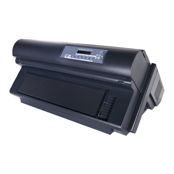
Printer Parts Figure 2. Printer Parts: Front and Rear View Quick Setup Guide... -
Page 11: Choosing A Suitable Location
Choosing a Suitable Location CAUTION: The 4247 printer weighs 21 kg (46 lbs). Two persons are required to lift Consider the following points when you choose the location for your printer: v The distance between the printer and the host computer must not exceed the length of the interface cable. -
Page 12: Removing The Shipment Locks
Removing the Shipment Locks Open all the printer covers and make sure that you remove all the shipment locks from the printer. Figure 4. Printer showing location of the Shipment Locks The following sections describe how to install the Operator Panel Overlay, the ribbon cartridge, and the Controller Board. -
Page 13: Step 2 - Installing The Ribbon Cartridge
Step 2 - Installing the Ribbon Cartridge 1. Find the ribbon cartridge among the accessories. Ribbon Guide Ribbon Winding Knob Cartridge Pins Figure 6. Ribbon Cartridge 2. Open the top cover using the small handles on either side of the top cover. 3. - Page 14 5. Slide and insert the ribbon guide between the print head and the ribbon guide mask holding it perpendicular to the print head. Make sure that the ribbon is inserted correctly between the print head and the ribbon guide mask. Figure 8.
-
Page 15: Replacing The Ribbon Cartridge
Replacing the Ribbon Cartridge 1. Make sure that the printer is turned off for at least 15 minutes. CAUTION: <2-51> The printhead may get hot during operation. Be careful when removing or replacing the ribbon. 2. Open the top printer cover. 3. -
Page 16: Step 3 - Installing The Controller Board
Step 3 – Installing the Controller Board The 4247 printer arrived with the Controller Board that you ordered. You must install the Controller Board (received with the printer) into the proper slot in the back of the printer before it can be used. Handling the Controller Board Attention: Do not remove the Controller Board from the protective package until instructed to do so. - Page 17 Figure 9. Removing the two screws on the metal plate. 3. Use the information under “Handling the Controller Board” on page 8 as you remove the Controller Board from its shipping box and from the protective package. 4. Align the left and right sides of the Controller Board with the guides in the printer and slide it into the slot.
- Page 18 6. Attach the Controller Board with the two screws using the screwdriver that came in the Controller Board box. Figure 11. Attaching the Controller Board. Quick Setup Guide...
-
Page 19: Step 4 - Starting The Printer
Step 4 – Starting the Printer Host Computer Connection This printer can be connected to your host computer with the interfaces available on the Controller Board you have found in the printer box and installed on the rear of the printer. There are two types of Controller Boards: 1. -
Page 20: Software Driver Selection
Software Driver Selection At this point it is necessary to configure your printer for your application package. The installation procedures depend upon the host environment. In a WINDOWS environment the printer supports the Plug & Play feature. Power Connection DANGER <1-11>... - Page 21 4. Turn the printer on, press the power switch in the I position (ON). Figure 13. Power switch in the I position (ON). Attention: If, for any reason, the Controller Board was not correctly installed in the printer, the printer will not work and the following audio/visual symptoms will occur: v The buzzer sounds continuously v The Operator Panel display is partially filled with solid black boxes...
-
Page 22: Step 5 - Selecting The Display Language
Step 5 – Selecting the Display Language The display messages for this printer can be displayed in eleven different languages (the default language is English). To select the language you want, proceed as follows: 1. Press the PROGRAM key and keep it pressed while powering on the printer until the following message is displayed: RELEASE KEY 2. -
Page 23: Step 6 - Loading Fanfold Paper
Step 6 – Loading Fanfold Paper This sequence describes how to load the fanfold paper with the Front1 push tractor (default). For the other paper paths please see the User's Guide you find on the CD-Rom. 1. Turn the printer on. 2. - Page 24 4. Space the paper guides along the tractor bar. Open the left and right sprocket covers. Figure 16. Opening the left and right sprocket covers. Quick Setup Guide...
- Page 25 5. Hold the fanfold paper in front of the sprockets and insert the paper perforation on the left sprocket pins and close the left sprocket cover. Figure 17. Inserting the paper perforation on the left sprocket pins. 6. Insert the paper on the right sprocket pins. HC0I0022 Figure 18.
- Page 26 7. Match the left sprocket for the first printing position, that is the left margin must match the ninth mark on the printer cabinet. Note: Aligning the left-hand edge of the paper past the 22 spacer on the printer cabinet will cause the paper to be misaligned with the Paper Load Sensor resulting in a '001 End of Forms' error.
- Page 27 HC0I0026 Figure 21. Closing the Push tractors cover. 10. Press the ON LINE key to take the printer OFF LINE. 11. Press the LOAD/FF key to load the paper into the printer. 12. Press the ON LINE key to put the printer ON LINE. Setting up your printer...
-
Page 28: Printing A Default Configuration Sheet
9. Press the TEAR key and tear off the printout at the perforation. Configuring the Printer See the 4247-L03 Printer: User's Guide on the CD-ROM for information about how to make and save printer configuration setting changes. Quick Setup Guide... -
Page 29: Maintenance & Troubleshooting
Maintenance & Troubleshooting Cleaning the Printer CAUTION: <2-22> Carefully follow all cleaning instructions, using only the materials and solutions recommended. Periodic cleaning will help keep your printer in top condition so that it will always provide optimal performance. Before you clean the printer: 1. -
Page 30: Lcd Display Messages
LCD Display Messages Table 1. Display Messages ALTERNATE This message appears to indicate that the Alternate functions of the operator panel keys have been selected pressing the ALTERNATE key. BUSY M1 This message appears to indicate that the printer is printing. It is busy. COVER OPEN When the printer cover is not closed correctly, the buzzer sounds and the display shows alternately these two messages. - Page 31 Table 1. Display Messages (continued) UNLOCKED MENU When the access to the Printer Setups has been unlocked at the power on, the printer displays this message. Setting up your printer...
-
Page 32: Error Messages
Error Messages When an error condition occurs: v The printer is disabled v The first message on the display indicates the error, while the second message gives more details concerning the error conditions. Press the ON LINE key to reset the error condition. If the error condition returns after performing the suggest solutions, call for service. -
Page 33: Options
Options Option Description Printer Stand For large fanfold paper quantity and dual fanfold handling. Front2 Push Tractor The Front2 push tractor is useful for handling a 2 fanfold. Controller Board There are two Controller Board options: 1. Allows a host connection to parallel, serial, and USB 2.0 interfaces. 2. - Page 34 Quick Setup Guide...
-
Page 35: Notices
Compuprint advises the customers not to use products for which the compliance to this safety rules are not warranted. Finally seek your dealer or contact a Compuprint office and be sure that are provided you the original consumables. - Page 36 European Union (EU) Conformity Statement Compuprint srl declares that this product is in compliance with the essential requirements and other relevant provisions of Directive 2006/95/EC, 2004/108/EC. Per the applicable requirements of EU directive 98/37/EC (“machines”) sound pressure of the above product (measured according to EN27779) does not exceed 70dBA.
- Page 38 MAN10292.00.00 Printed in Italy MAN10292.00.00...
Need help?
Do you have a question about the L03 and is the answer not in the manual?
Questions and answers