Table of Contents
Advertisement
Quick Links
Advertisement
Table of Contents

Subscribe to Our Youtube Channel
Related Manuals for Compuprint 4051 plus


Summary of Contents for Compuprint 4051 plus
- Page 1 4051 plus 4056 plus User Manual...
- Page 3 Compuprint advices the customers not to use products for which the compliance to this safety rules are not warranted. Finally seek your dealer or contact a Compuprint office and be sure that are provided you the original Compuprint consumables. A78408744-002...
-
Page 4: Fcc Notes
FCC Notes FCC Notes This equipment has been tested and found to comply with the limits for a Class B digital device, pursuant to Part 15 of the FCC Rules. These limits are designed to provide reasonable protection against harmful interference when the equipment is operated in a commercial environment. -
Page 5: Safety Information
Safety Information Safety Information The following areas of the printer should be covered for safety reasons: The above openings must always be protected with their cover when the corresponding option is not installed. Do not touch inside and do not insert any object into these openings or into the gears. -
Page 6: Table Of Contents
Safety Information..................iii Table of Contents ................... iv Getting to Know Your Printer ..............1 Printer Features ..................... 1 4051 plus Model Specific Features ............1 4056 plus Model Specific Features ............1 Common Features ..................1 Unpacking Your Printer................. 2 Printer Parts.................... -
Page 7: Table Of Contents
Table of Contents Power on Configuration Setup..............23 Entering the Power-On Configuration ............ 23 Program Setup....................32 Entering the Program Setup..............32 Paper Handling ..................... 38 Paper Specifications ..................38 Fanfold Paper ................... 38 Cut Sheets....................38 Cut Sheets..................... 39 Loading Cut Sheets .................. - Page 8 Table of Contents A78408744-002...
-
Page 9: Getting To Know Your Printer
Getting to Know Your Printer Printer Features 4051 plus Model Specific Features • 9 Needle Print Head • Draft printing at 480 cps and in Letter Quality at 120 cps • IBM Proprinter XL III, EPSON FX Series emulations •... -
Page 10: Unpacking Your Printer
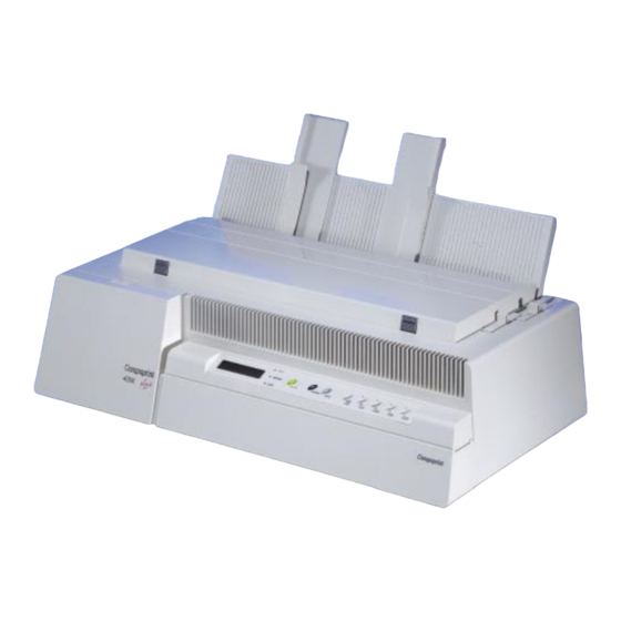
Getting to Know Your Printer Unpacking Your Printer Together with the user manual, the following items are included in the box: Notify any damage to your supplier. Printer Parts Front View A78408744-002... -
Page 11: Rear View
Setting Up Your Printer Rear View Setting Up Your Printer Choosing a Suitable Location Consider the following points when you choose the location for your printer: • The distance between the printer and the host computer must not exceed the length of the interface cable; •... -
Page 12: Printer Assembly
Setting Up Your Printer Printer Assembly Ribbon Cartridge Installation It is advisable to insert the ribbon cartridge while the printer is turned off. However, your printer can be turned on during this procedure, but do not forget that it must be disabled to print (Wait displayed and led turned off). - Page 13 Setting Up Your Printer 3. Pull the paper thickness lever towards the front of printer facilitate ribbon insertion 4. Remove the new ribbon cartridge from bag. Remove and discard the holdfast (1) that blocks the ribbon. Turn the tension knob (2) to tighten the ribbon.
- Page 14 Setting Up Your Printer 6. Push the cartridge gently down while turning the tension knob (1). Make sure that the cartridge clips into place (2). 7. To tighten the ribbon, turn the tension knob in the direction shown arrow ribbon cartridge.
-
Page 15: Paper Chute Installation
Setting Up Your Printer 9. Move the paper thickness lever according to the paper type: • If a cut sheet is loaded move the lever towards the back of the printer. • If a multicopy chemical paper is loaded, first move lever completely towards the back of... - Page 16 Setting Up Your Printer 1. Insert the hook on the left side of the paper chute in the groove situated near paper entry slot. The figure shows the back of the printer and the paper chute in the back position for a good view of the hook and groove.
-
Page 17: Host Computer Connection
Setting Up Your Printer 3. If you wish to position the paper chute down, lift it towards the back of the printer and push it gently down until it stops. If you wish to place the paper chute in the raised position, lift it and hook it firmly. Host Computer Connection This printer can be connected to your host computer via two available interfaces. -
Page 18: Serial Connection
Follow the instructions in the readme file you find on the CD-ROM. In a WINDOWS 95 environment the printer supports the Plug & Play feature. The printer drivers of all Compuprint printers can be found at the Internet Address http://www.compuprint.net. Power Connection... - Page 19 Setting Up Your Printer 1. Make sure that the power switch at the rear of the printer is on "printer off" position. Insert one end of the power cable plug into the printer connector placed on the rear of the printer. 2.
-
Page 20: Selecting The Display Language
Selecting the Display Language Selecting the Display Language The display messages for this printer can be displayed in two different languages: English (Default) and Italian. To select the language that you prefer, proceed as follows: 1. Enter the Power on Configuration procedure. •... -
Page 21: Configuring The Printer
(Ready, Wait, Busy, Quiet.), the current macro (M1, M2, M3, M4) and the selected emulation (IBM XL III or EPSON FX for the 4051 plus printer and IBM XL 24E, IBM XL24 AGM and EPSON for the 4056 plus printer) as follows:... - Page 22 Displayed when the paper ejection is not successful 2. Remove paper This message appears on the display immediately 4051 plus after turning the printer on to indicate that it is or 4056 plus initializing to its power on setting. The print head moves to its initial position.
- Page 23 Configuring the Printer Fanfold thru ASF This is one of the messages that will be displayed when you press (Shift function). Press the PATH SHIFT key to select the handling of the fanfold paper with the Automatic Sheet Feeder (option) installed. Displayed while the printer is turned on.
-
Page 24: Indicators
Configuring the Printer Serial I/F error Displayed when a DSR, DCD, or CTS signal fault occurs. Displayed every time that the key is pressed to Shift SHIFT indicate that the Shift function is selected. Displayed when the printer is in stand-by status. Stand-by Displayed as long as the top cover is open. - Page 25 Configuring the Printer ON LINE Key • ON LINE Normal Pressing this key you will obtain different results Function depending on the printer status: • When the indicator is lit on, pressing this READY key you will cause the stop of the printing at the indicator end of the current line;...
- Page 26 Configuring the Printer FF/PARK Key FORM Normal Pressing this key while the printer is offline causes: • FEED Function The paper, if loaded, advances at new page or, if parked, is positioned on the first printable line. • The cut sheet, if loaded, is ejected (max. 21 inches) or a new cut sheet will be loaded.
- Page 27 The font messages are: Draft - Courier - Gothic - OCR-A - OCR-B for the 4051 plus printer and Draft - Courier – Roman – Boldface – Prestige – Script -Presentor - OCR-A - OCR-B for the 4056 plus printer.
- Page 28 Configuring the Printer PROGRAM Key PROGRAM Normal Keeping pressed this key while you turn on the Function printer you will enter Power on Configuration Setup. Pressing this key when the printer is unable to print, (indicator unlit) you will enter the READY Program Setup and the Program Function of keys are enabled.
-
Page 29: Buzzer
Configuring the Printer Buzzer This printer is provided with a buzzer to indicate particular conditions according to the problem detected.: • 1 short "beep" (0,25 sec): the BEL code has been sent; when the buzzer sound stops, the printer returns to normal operation. •... -
Page 30: Printer Setups
Printer Setups Printer Setups You can customize the printer depending on your needs via the Power on Configuration Setup and the Program Setup procedures. Entering the Printer Setups key allows to enter the Printer Setups. PROGRAM • Keep pressed the key while powering the printer on to enter PROGRAM the Power on Configuration Setup... -
Page 31: Power On Configuration Setup
1. Make sure that the printer is turned off. 2. Keep pressed the button key while turning on the printer. The PROGRAM 4051 plus or 4056 plus message will be displayed then Release button message. 3. Release the button key and the following message will be displayed: INSTALLATION... - Page 32 Printer Setups IBM Mode PROTOCOL ↑ → or ← ↑ or ↓ → or ← IBM MODE IBM C-SET (1/2) IBM set... ↓ ↑ or ↓ → or ← NATION CP 437 ... ↑ or ↓ → or ← EPSON MODE 20 CPI 20 CPI no IBM C-SET (1/2)
- Page 33 Printer Setups - EPSON National Character Sets EPSON C-SET ↑ → or ← ↑ or ↓ NATION USA (*) ↓ ↑ or ↓ ↑ or ↓ EPSON C-SET ISO 8859/15 Selection of the following EPSON National character sets: USA (*) FRANCE GERMANY ENGLAND...
- Page 34 Printer Setups Tear/View Mode LINE MODE ↑ → or ← ↑ or ↓ TEAR/VIEW MODE Auto.advance. 1s (*) ↓ ↑ or ↓ ↑ or ↓ LANGUAGE Auto.advance. 5s ↑ or ↓ Manual advance ↑ or ↓ No tear Auto.advance Paper moves automatically to the tear/view position 1s ...
- Page 35 Printer Setups Interface Time-out INTERFACE TYPE ↑ → or ← ↑ or ↓ TIME-OUT I/F 2 seconds (*) ↓ ↑ or ↓ ↑ or ↓ INPUT BUFFER 30 seconds This function defines the time duration (2 to 30 sec.) after which the interface switches to the other.
- Page 36 Printer Setups Serial Interface Type SLCT-IN SIGNAL ↑ → or ← ↑ or ↓ SERIAL TYPE RS232C (*) ↓ ↑ or ↓ RS422A SERIAL MODE This function selects the serial interface type: RS-232/C or RS-422/A. Serial Connection Mode SERIAL TYPE ↑...
- Page 37 Printer Setups Buffer Control PARITY BIT ↑ → or ← ↑ or ↓ BUFFER CONTROL ↓ ↑ or ↓ XON/XOFF (*) ROBUST XON This function selects the buffer control protocol: DTR or XON/XOFF. Robust XON BUFFER CONTROL ↑ → or ← ↑...
- Page 38 Printer Setups PRINT STATUS Function • Press the → key to select the function. The message Printing test will displayed while the following output will be printed: 405x plus CONTROLLER:78XXXXXX Rel.:x.xx GENERATOR: 78XXXXXX Rel.:x.xx OPTIONS CURRENT VALUES MACRO1* MACRO2 MACRO3 MACRO4 FONT Draft...
- Page 39 Printer Setups RECALL FACTORY Function • Press the → key to select this function. The values of the functions return to the factory default setting. All values of the functions are reset to the factory default ones in both Power on Configuration Setup and Program Setup.
-
Page 40: Program Setup
Printer Setups Program Setup default values marked with asterisk (*). These are the available functions: This function defines four different macros and allows to SELECT MACRO configure the printer for different job types. This function allows the adjustment of the mechanical PRINT parameters and the tuning of the first printing line. - Page 41 OCR-A Selects the type of character to use : Draft, Courier, Gothic, OCR-A, OCR- B. for the 4051 plus model and Draft Courier, Roman, Prestige, Presentor OCR- A, Script, Boldface. OCR-A and OCR-B may be selected only when the non- proportional pitch is selected.
- Page 42 Printer Setups Top Margin PAGE LENGTH ↑ → or ← ↑ or ↓ TOP MARGIN Line #1 (*) ↓ ↑ or ↓ ↑ or ↓ BOTTOM MARGIN Line #X This function selects the top margin defined as n° of lines (at 1/6”). The value X corresponds to the n°...
- Page 43 Printer Setups Right Margin LEFT MARGIN ↑ → or ← ↑ or ↓ RIGHT MARGIN Column 1 ↓ ↑ or ↓ ↑ or ↓ SLASHED ZERO Column 136 (*) This function sets the right margin defined as number of columns. The physical margin position depends on the selected horizontal spacing.
- Page 44 Printer Setups PRINT ADJUSTMENT Function Bidirectional Print Alignment SELECT MACRO. TEAR PERFO ALIGN ↑ ↑ → or ← → or ← ↑ or ↓ BIDI. ALIGNMENT: Offset: +6 PRINT ADJUSTMENT ↓ ↓ ↑ or ↓ ↑ or ↓ PRINT STATUS TOP OF FORM Offset: -6 This function adjusts the bidirectional printing in a range between - 6 and...
- Page 45 Printer Setups PRINT STATUS Function Press the → key to select the function. The message Printing test will displayed while the following output will be printed: 405x plus CONTROLLER:78XXXXXX Rel.:x.xx GENERATOR: 78XXXXXX Rel.:x.xx OPTIONS CURRENT VALUES MACRO1* MACRO2 MACRO3 MACRO4 FONT Draft Draft...
-
Page 46: Paper Handling
Paper Handling Paper Handling Paper Specifications Use the correct paper in your printer for obtaining good results in your printout. See the information table below: Fanfold Paper Width: Minimum 76 mm (3 inches) Maximum (*) 406 mm (16.55 inches) Minimum 76 mm (3 inches) Length: Minimum... -
Page 47: Cut Sheets
Paper Handling Cut Sheets Cut sheets are inserted from the top of the printer. You can load cut sheet whether fanfold paper is inserted or not. If no fanfold paper is present, proceed as follows; otherwise, go to "Switching From Fanfold Paper to Single Sheet" section. Loading Cut Sheets 1. - Page 48 Paper Handling 3. Move the paper thickness lever according to the paper type: • If a cut sheet is loaded move the lever towards the back of the printer. • If a multicopy chemical paper is loaded, first move lever completely towards the back of the printer, then 1 notch towards the front of the printer for each copy.
-
Page 49: Fanfold Paper
Paper Handling 5. Feed the cut sheet in the slot. Press the key. The paper will be LOAD loaded to the first printable line. The paper is positioned at the first printable line at 1/6 inch from the top edge of the paper. The last printable line of the sheet is positioned at 0.83 inch (21 mm) from the bottom edge of the paper. - Page 50 Paper Handling 2. Open the tractor cover until it clips into place. 3. Unlock the sprocket on the side of the interface connector and, if it is not already positioned, slide it to the right until it stops. 4. If you wish the first column in a particular position, the ruler under the tractor should be helpful to position the sprocket.
- Page 51 Paper Handling 6. Unlock the other sprocket and position it in accordance with the paper width. Slide the spacers evenly along the tractor bar 7. Open the sprocket covers. 8. Position the holes in the paper over one sprocket and then over the other.
- Page 52 Paper Handling 9. Close the sprocket covers 10. Adjust the two sliders on the tractor cover in alignment with the spacers and close the cover firmly. 11. Put the paper chute in the down position by lifting it towards the back of the printer and pushing gently down until it stops.
-
Page 53: Parking Fanfold Paper
Paper Handling 12. Place the drive selection lever in fanfold position (fanfold drawing) and make sure that Fanfold is selected by pressing key ( function) on the PATH SHIFT operator panel. 13. If the printer is turned off, turn the printer on (see "Power Connection” section before). -
Page 54: Switching From Fanfold Paper To Cut Sheet
Paper Handling • When the fanfold paper to park is too long, two messages will be alternatively displayed: 1. paper and 2. Tear-off Remove paper. Tear the printed paper and press again the key. PARK • When you need to load again the fanfold paper, make sure that the drive selection lever is in fanfold position and that the paper type function) selection is Fanfold. -
Page 55: Top Of Form Adjustment
Paper Handling Top of Form Adjustment The Top of Form Adjustment procedure allows you to adjust the position of the first printable line and therefore it is advisable to perform it immediately after a paper loading. Turn the printer on , if it is not, and proceed as follows: Make sure that the printer is not printing. -
Page 56: Tear Off Line Adjustment
Paper Handling Tear Off Line Adjustment The Tear Off Line Adjustment procedure allows you to adjust the position of the fanfold perforation in order to tear it against the printer tear off border on the cover. This procedure is available only if the Program Setup is previously entered. -
Page 57: Printer Maintenance And Troubleshooting
(Wait message displayed). Make sure that the new ribbon cartridge is an original Compuprint spare part. If it is not so the quality and reliability level declared in the product features won’t be assured. -
Page 58: Printing The Self Test
Printer Maintenance and Troubleshooting 2. Move the printer carriage to the center of the printer. 3. Lift the cartridge off until the clip release it. Now, you are ready to insert a new ribbon cartridge. Follow from step 2 of "Ribbon Cartridge Installation"... -
Page 59: Error Handling
Printer Maintenance and Troubleshooting Error Handling The following table will help you to identify and solve problems which may occur when using the printer. If the problem is not listed, or if it is not corrected by any of the methods suggested, contact your supplier for help. Error Message Description Problem Cause... - Page 60 Printer Maintenance and Troubleshooting Problem Cause Solution Try to eject the paper using ↑ and ↓ in display Error paper shows handling procedure MICRO FEED function. Remove paper display unrecoverable Turn the printer off. Make sure that shows Carriage carriage error occurred the ribbon is not blocked inside the cartridge by turning the tension knob, error...
-
Page 61: Options
Options Options Automatic Sheet Feeder This Automatic Sheet Feeder (ASF) provides fast and automatic feeding of single sheets and multi-part forms on your printer. This option is quickly and easily installed onto the printer by the operator. No tools or special equipment are necessary. -
Page 62: Preparing The Printer
Options Preparing the Printer Make sure that no paper is present in the printer and that the Automatic Sheet Feeder loading is selected via your printer operator panel (see “Configuring the Printer” section). 1. Turn the printer off. 2. Remove the printer cover by pushing down simultaneously the two buttons in the front part of the cover and lifting it out. - Page 63 Options • lift the right side of the paper chute; • unhook the left side of the paper chute. 4. Slide the rubber rollers (1) of the paper bail to the extreme right side. Remove the plastic mask (2) that protects the feeding mechanism on the right side of the platen.
-
Page 64: Installing The Automatic Sheet Feeder
Options 5. Put the drive selection lever in the single sheet position. Installing the Automatic Sheet Feeder 1. Install the rear paper stackers. 2. Clip the two paper stackers (1) onto the metal strip in front of the paper sorter (2). - Page 65 Options 3. If you want to install the second bin on your ASF, remove the cover plates from the rear of the first bin. 4. Insert the second bin into the first bin of ASF, ensuring that the two support arms snap in place. Remember that once you have placed the second bin, it is not possible to separate it from the first bin 5.
-
Page 66: Paper Specifications
Options Paper Specifications The following specifications should be adhered to in order to assure reliable feeder operation. See the following tables: Cut Sheet Width: Minimum 145 mm (5.7 inches) Maximum 420 mm (A3) Length: Minimum (Bin 1) 145 mm (5.7 inches) Minimum (Bin 2) 203 mm (8 inches) Maximum... -
Page 67: Paper Loading
Options Paper Loading Make sure that all preliminary operations of preparing the printer are executed, then follow the sequence: 1. Lift the lever (1) on the left side of the ASF to open the paper bin. 2. Unlock the left paper bin guide (1) by pressing down the lever (2) positioned on top of the guide and then lock the guide in place. - Page 68 Options 4. Fan the paper thoroughly and stack it firmly in the bin. 5. Lock the paper bin guides by lifting the levers up. Close the paper bin by pushing its lever down. • Whenever the bin is opened, reposition the paper in the bin •...
-
Page 69: How To Keep The Automatic Sheet Feeder Clean
Options and close them. Using Fanfold Paper through Automatic Sheet Feeder Your printer allows to load the fanfold paper with the Automatic Sheet Feeder (option) installed. The paper width must be maximum 15 inches (381 mm) and it is advisable to test it so that this feature can be correctly performed. -
Page 70: Removing The Automatic Sheet Feeder
Options Removing the Automatic Sheet Feeder When the ASF is no longer required, do not forget to disable its use by selecting another type of paper loading via your printer operator panel, see “Operator Panel Presentation” before. 1. Turn the printer off and remove the ASF cover. 2. -
Page 71: Problem Solving
Options Problem Solving The following table will help you to identify and solve problems which may occur when using the ASF. If the problem is not listed, or if it is not corrected by any of the methods suggested, contact your supplier for help. Problem Cause Solution... -
Page 72: Printer Specifications
Result 17.1 17.1 Proportional spacing employs the same density definition as for 10 cpi, but with a cell dimension tuned on the character widths. Vertical Spacing Vertical 4051 plus: 1/6’’, 1/8’’, 1/12’’, 1/72’’, 1/144’’ ’ ’ ’ ’ ’ ’... - Page 73 Latin/Greek (ISO 8859/7), Latin/Hebrew (ISO 8859/8), Latin5 (ISO 8859/9), Latin9 (ISO 8859/15) Fonts 4051 plus: Draft, Courier, Gothic, OCR-A, OCR-B 4056 plus: Draft, Courier, Roman, Boldface, Prestige, Script, Presentor, OCR-A, OCR-B Print Attributes Compressed, Double Width, Double Height, Subscript (*), Superscript, Underline (*), Overscore,...
- Page 74 8,54 to 38,1 cm (6’’ to 15’’) Length: Bin 1: 17,78 to 35,56 cm (7’’ to 14’’) Bin 2: 20,32 to 35,56 cm (8’’ to 14’’) Physical and Electrical Characteristics 4051 plus 4056 plus Emulations IBM Proprinter XL III IBM Proprinter XL 24...
- Page 75 Printer Specifications Physical Dimensions Height 173 mm (6,7 “) Width 615 mm (24,2”) Depth 310 mm (12,2”) Weight 15 kg Environment Conditions Storage Conditions Temperature -40° to 50° C Relative Humidity 10%t o 90% RH (non condensing) Operating Conditions Temperature 10°...
Need help?
Do you have a question about the 4051 plus and is the answer not in the manual?
Questions and answers