
Subscribe to Our Youtube Channel
Related Manuals for Tenma 72-10175


Summary of Contents for Tenma 72-10175
- Page 1 USER’S MANUAL Tenma 72-10175 www.tenma.com Tenma Test Equipment 405 S.Pioneer Blvd.Springboro,OH 45066...
- Page 2 TENMA 72-10175 DIGITAL OSCILLOSCOPE USER’S MANUAL 72-10175...
-
Page 3: Table Of Contents
Content General Safety Summary ……..………………………….…..3 CHAPTER 1: Getting Started…...…………………………... 4 System Requirement..………………………………..5 Install Software..………………………………...…6 Install Driver....………………………………..11 General Features..………………………………….16 General Check....……………………………..17 Probe Compensation....…………………..17 Functional Check....………………..……..19 Self Calibration............21 Accessaries.............22 CHAPTER 2: Operating Basics……………………………..23 The User’s Inerface…………………………………...24 The Vertical System…...………………………..30 The Horizontal System……………………..……...32 The Trigger System......……………...33 Input Connectiors..…………………………………...35 CHAPTER 3:Functions... -
Page 4: General Safety Summary
TENMA 72-10175 DIGITAL OSCILLOSCOPE General Safety Summary Review the following safety precautions carefully before operate the device to avoid any personal injuries or damages to the device and any products connected to it. To avoid potential hazards use the device as speci¿ed by this user’s guide only. -
Page 5: Chapter 1: Getting Started
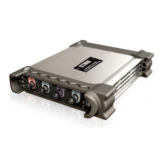
Chapter 1 Getting Start The 72-10175 is small, lightweight, portable oscilloscope which does not require external power! The 72-10175 is ideal for production test,research,design and any other applica- tions involving analog circuits test and troubleshooting, as well as education and training. -
Page 6: System Requirement
TENMA 72-10175 DIGITAL OSCILLOSCOPE System Requirement To run the oscilloscope software, the needs of computer con¿guration are as follows: Minimum System Requirements Operating System Window NT/2000/XP/VISTA/Win7 Processor 1.00GHz processor Memory 256MB Disk Space 500M disk free space Screen resolution 800 x 600 Recommended Con¿guration... -
Page 7: Install Software
Install Software Caution: You must install the software before using the oscilloscope. 1. While in Windows, insert the installation CD into the CD-ROM drive. 2. The installation should start up automatically. Otherwise in Windows Explorer, switch to the CD-ROM drive and run Setup.exe. 3. - Page 8 TENMA 72-10175 DIGITAL OSCILLOSCOPE 5. Check the setup information. Click Next to start copying of ¿les.
- Page 9 6. This Status dialog is displayed during copying of ¿les.
- Page 10 TENMA 72-10175 DIGITAL OSCILLOSCOPE 7. Updating Your System Con¿guration.
- Page 11 8. The installation is complete.
-
Page 12: Install Driver
TENMA 72-10175 DIGITAL OSCILLOSCOPE Install Driver 1. Connect the A-Type Plug of USB cable to your PC’S USB port. 2. Connect the B-Type Plug of USB cable to USB’S USB port. 3. New hardware is found. 4. New hardware search wizard starts. - Page 13 5. Select the speci¿c location.
- Page 14 TENMA 72-10175 DIGITAL OSCILLOSCOPE 6. New hardware search wizard starts to search the driver.
- Page 15 7. New hardware wizard installs “USB DRIVER ”.
- Page 16 TENMA 72-10175 DIGITAL OSCILLOSCOPE 8. The wizard has ¿nished installing for “USB DRIVER”.
-
Page 17: General Features
General Features Product features: Four channel,Bandwidth: 60MHz Maximum real-time sample rate: 200MSa/s Memory depth: 10K-16M points Automatic setup for ease of use (AUTOSET); Pass/Fail; Built-in Fast Fourier Transform function(FFT); 20 Automatic measurements; Automatic cursor tracking measurements; Waveform storage, record and replay dynamic waveforms; User selectable fast offset calibration;... -
Page 18: General Check
TENMA 72-10175 DIGITAL OSCILLOSCOPE General Check Please check the instrument for the following steps before use. Check the shipping container for damage: Keep the damaged shipping container or cushioning material until the contents of the shipment have been checked for completeness and the instrument has been checked mechanically and electrically. - Page 19 Correctly Compensated Over compensated...
-
Page 20: Functional Check
TENMA 72-10175 DIGITAL OSCILLOSCOPE Under Compensated If necessary, use a non-metallic tool to adjust the trimmer capacitor of the probe for the Àattest square wave being displayed on the oscilloscope. Repeat if necessary. WARNNING: To avoid electric shock while using the probe, be sure the perfection of the insulated cable, and do not touch the metallic portions of the probe head while it is con- nected with a voltage source. - Page 21 Input a signal to a channel of the oscilloscope The oscilloscope is equipped with four channels plus external trigger. Please input signal in the following steps: 1. Set the attenuation switch on the probe as 10X and connect the probe on the oscil- loscope with CH1.
-
Page 22: Self Calibration
TENMA 72-10175 DIGITAL OSCILLOSCOPE 3. Attach the tip of probe and ground nip to the Connector of Probe compensator. Click the button. A square wave will be displayed within a several seconds. (Approximately 1 kHz, 2V, peak- to- peak). 4. Inspect CH2 ,CH3 and CH4 with the same method. Repeat steps 2 and 3. -
Page 23: Accessaries
Accessories All the accessories listed below are standard accessories for the oscilloscope: Probe×2 (1.5m), 1:1, (10:1) Passive Probes A User’s Guide An USB Cable A PC software of the oscilloscope... -
Page 24: Chapter 2 Operating Basics
TENMA 72-10175 DIGITAL OSCILLOSCOPE Chapter 2 Operating Basics The User’s Interface The Menu System The Vertical System The Horizontal System The Trigger System Input Connectors... - Page 25 The User’s Interface Click the software icon on the desk after you ¿nished the software setting and equipment connecting. Then a user interface will be showed as follows: In addition to displaying waveforms, the display area is ¿lled with many details about the waveform and the oscilloscope control settings.
- Page 26 TENMA 72-10175 DIGITAL OSCILLOSCOPE The user can change Time/Div, format in the panel. 5. The Vertical Panel The user can turn on/off the CH1/CH2/CH3/CH4. Also the user can change the CH1/ CH2/CH3/CH4 volt/div, coupling and probe attenuation. 6. The Trigger Panel In this panel, the user can change the trigger mode, sweep, source and slope.
- Page 27 19. A window that shows the display waveform in buffer position. 20. Marker shows horizontal trigger position. 21. Trigger status indicates the following: AUTO: The oscilloscope is in auto mode and is acquiring waveforms in the absence of triggers. Trig’D: The oscilloscope has seen a trigger and is acquiring the post trigger data. WAIT: All pretrigger data has been acquired and the oscilloscope is ready to accept a trigger.
- Page 28 TENMA 72-10175 DIGITAL OSCILLOSCOPE 3. Setup: Setup setting 4. Display: Change wave display type 5. Cursor: Set Cursor measure type 6. Measure: Set measurement parameters 7.Acquire: Run ,Stop or other operation setting...
- Page 29 8. Utility: Utility setting 9. Window: Window setting 11. Help : Access help ¿le...
- Page 30 TENMA 72-10175 DIGITAL OSCILLOSCOPE...
-
Page 31: The Vertical System
The Vertical System Click “Setup”->” Vertical” The following ¿gure shows the vertical Setup window. It shows the vertical parameters setting. 1. Select channel : User can select the channel by clicking the Combo box. 2. ON/OFF: Turn on or off the selected channel. - Page 32 TENMA 72-10175 DIGITAL OSCILLOSCOPE 3. VOLTS/DIV: Set the selected channel voltage range. 4. Coupling: Set the selected channel to DC/AC. 5. Probe: Set the Select one according to the probe attenuation factor to ensure correct vertical scale reading 6. BW Limit: Reject the frequency component higher than 20MHz.
-
Page 33: The Horizontal System
The Horizontal System Click ”Setup”->“Horizontal” The following ¿gure shows the Horizontal System window. It shows the horizontal pa- rameters settings. 1. Time/DIV: leads the setting of the time base parameters 2. Format: leads the setting of the horizontal format parameters... -
Page 34: The Trigger System
TENMA 72-10175 DIGITAL OSCILLOSCOPE The Trigger System Click “Setup”-> “Trigger” The following ¿gure shows the trigger system control. 1. Trigger Mode: Sets the trigger mode 2. Trigger Sweep: Selects the trigger sweep mode to AUTO, NORMAL or SINGLE... - Page 35 3. Tirgger Source: Selects the trigger source to CH1, CH2, ALT, EXT or EXT/10 4. Trigger Slope: Selects the edge trigger slope to Positive or Negative slope...
-
Page 36: Input Connectiors
TENMA 72-10175 DIGITAL OSCILLOSCOPE Input Connector CH1/CH2/CH3/CH4: Input connectors for waveform display. EXT.: Input connector for an external trigger source. Use the Trigger Menu to select the Ext. or Ext./10 trigger source. Other Connector: GND. : Ground terminal USB PORT: Connect the B-Type Plug of USB cable to this port. -
Page 37: Chapter 3:Functions
Chapter 3 Understanding Oscilloscope Functions Set Oscilloscope Set Vertical System Set Horizontal System Set Trigger System Save/Load Utility Function Measure Signal Zoom In/Out Waveforms Acquire Signal Print... - Page 38 TENMA 72-10175 DIGITAL OSCILLOSCOPE Setup the Oscilloscope Using “AUTOSET” to display a signal automatically Auto setup functions one time each time you push the “AUTOSET” button. The function obtains a stable waveform display for you. It automatically adjusts the vertical scale, horizontal scale and trigger settings.
-
Page 39: Set Vertical System
Set Vertical System Set Channel Click “Vertical” in “Setup” Menu. The Channel Selection The Channel Control Panel in sidebar The Vertical function: Turn ON/Off: Turn on/off the channel Volt/DIV: Select the channel voltage/div Coupling: Select the channel coupling Probe: Select the channel probe attenuation Filter: Select software ¿lter Reset: Set the channel vertical position to zero Invert: Turn on/off the invert function. - Page 40 TENMA 72-10175 DIGITAL OSCILLOSCOPE You can also change the selected channel voltage in sidebar You can left click and drag the mouse on the knob to change the voltage. Set Channel Coupling Click “Coupling” in “Vertical Setup” window In the sidebar, you can change the channel coupling too.
- Page 41 Click “Probe” in Vertical Setup window to select the probe attenuation The probe setting window in the sidebar Note: The attenuation factor changes the vertical scale of the oscilloscope so that the measurement results reÀect the actual voltage levels at the probe tip. Invert The invert function turns the displayed waveform 180 degrees, with respect to the ground level.
- Page 42 TENMA 72-10175 DIGITAL OSCILLOSCOPE The following picture shows the waveform of inversion:...
- Page 43 Set the Channel Bandwidth Limit The oscilloscope is set to full bandwidth and will pass the high frequency component in the signal if the “BW Limit” was turned off. The oscilloscope will reject the frequency component higher than 20MHz if the “BW Limit”...
- Page 44 TENMA 72-10175 DIGITAL OSCILLOSCOPE ON/OFF: Turn On/Off the MATH Channel. Source A/B: Set the sources of the math channel. Operate: Set operates type of the math channel. Volt/DIV: Set the resolution of the math channel. Probe: Set the math channel probe attenuation.
- Page 45 Operate Four Types: A + B Add source A and source B A - B Subtract source B from source A A × B Multiply source A by source B Convert a time-domain signal into its frequency components (spectrum). In this function, use the addition, subtraction, multiplication and FFT function to operate and analyze the waveform.
- Page 46 TENMA 72-10175 DIGITAL OSCILLOSCOPE Click “REF” in “Setup” menu to set REF channel. The Reference Channel Function: On/Off: Turn on/off the reference channel. Volt/DIV : Select the resolution of the reference channel. Load: Load the reference waveform from the “.rfc” ¿le from your computer.
- Page 47 The save ¿le window will appear after you selected the saved source. The Reference Waveform Display Window: Note: If you turn on the “Reference” channel, the load ¿le window will appear.
-
Page 48: Set Horizontal System
TENMA 72-10175 DIGITAL OSCILLOSCOPE Setup Horizontal System Change Time/Div The “Time/Div” Selects the horizontal Time/DIV (scale factor) for the main or the window time base The Horizontal Panel Click the blue knob can change Time/Div. If the waveform acquisition is stopped, Time/Div control expands or compresses the waveform. - Page 49 In Roll mode, the waveform display rolls from right to left. No trigger or horizontal offset control of waveforms is available during Roll Mode, and it’s only available when set to 1s/div or slower. Note: If the time/div bigger than 1s, the format will change to Roll mode automatically. Change Horizontal Position Double click the channel button to set the trigger point to the horizontal center of the screen.
- Page 50 TENMA 72-10175 DIGITAL OSCILLOSCOPE Set Trigger System Set Edge Trigger The trigger determines when the oscilloscope starts to acquire data and display a wave- form. When a trigger is set up properly, it can convert unstable displays or blank screens into meaningful waveforms.
- Page 51 CH1: Select CH1 as trigger signal CH2: Select CH2 as trigger signal CH3: Select CH3 as trigger signal CH4: Select CH4 as trigger signal EXT: Select EXT as trigger signal Slope: Set the slope to Rising (+) or Falling (-). Rising: Trigger on rising edge Falling: Trigger on falling edge The user can also change the trigger setting on trigger panel in sidebar.
- Page 52 TENMA 72-10175 DIGITAL OSCILLOSCOPE The user can turn on “HF Rejection” to ignore triggers from higher frequencies (20M above). Set Pulse Trigger Pulse trigger occurs according to the width of pulse. The abnormal signals can be de- tected through setting up the pulse width condition.
- Page 53 NORMAL: Acquire waveform when trigger occurred. SINGLE: Acquire waveform when trigger occurred then stop Source: You can use the trigger source options to select the signal that the oscilloscope uses as a trigger. The source can be any signal connected to a channel BNC, or to the EXT.
- Page 54 TENMA 72-10175 DIGITAL OSCILLOSCOPE The user can also change the trigger setting on trigger panel in sidebar. When the alternative trigger is on, the trigger sources come from two vertical channels. This mode can be used to observe two non-related signals. You can choose two different trigger modes for the four vertical channels.
- Page 55 Trigger Type: Set the Trigger Type to Edge or Pulse. PW Condition: Set the PW Condition to the following condition. +More : +Pulse width more than set pulse condition. +Less : +Pulse width less than set pulse condition. +Equal : +Pulse width equal to set pulse condition. -More : -Pulse width more than set pulse condition.
-
Page 56: Set Trigger System
TENMA 72-10175 DIGITAL OSCILLOSCOPE Save/Load Save Click “File” in main menu to save waveform, setups and screen 1. Save Data Save waveform data as a type ¿le... - Page 57 2. Save Setup Save the current oscilloscope setup to ¿le 3. Save Image Save the software display window as a .bmp or .jpg ¿le Load Click “File” in main menu to recall saved waveform, setup 1. Load Data Load the waveform that had saved as a type ¿le 2.
-
Page 58: Utility Function
TENMA 72-10175 DIGITAL OSCILLOSCOPE Utility/Function Record and Play Back Click “Record” in “Utility” menu. The Record window will display. The following picture shows the Record Interface. - Page 59 This function can record input waveform form CH1,CH2,CH3, or CH4. The maximum record length is 1000 frames. Record Setup window Source: Select record source channel. (CH1, CH2, CH3 or CH4) End Frame:...
- Page 60 TENMA 72-10175 DIGITAL OSCILLOSCOPE Set the number of record times. The max frames are 1000. Record: Record counter, displays the record frames. “Start” button: Start to record frames. After you start to record waveforms, this button changes to “Stop” button. It stops recording waveforms.
- Page 61 Pass/Fail Click “Pass/Fail” in “Utility” menu The Pass/Fail window appears: The Pass/Fail function monitors changes of signals and outputs pass or fail signals by comparing the input signal with the pre-created mask. Control Setting...
- Page 62 TENMA 72-10175 DIGITAL OSCILLOSCOPE Source: Select the Pass/Fail channel Output: Select the Pass/Fail output condition Stop When Output: If it was checked, the Pass/Fail will stop when output. Mask Setting Vertical: Set the vertical limit range Horizontal: Set the horizontal limit range...
- Page 63 Click this button to create Pass/Fail area according to the mask “Save” button: Click this button to save the setups to ¿le. “Load” button: Click this button to load the saved setups ¿le. Information Display Fail: Displays the fail waveform number Pass: Displays the pass waveform number Total:...
- Page 64 TENMA 72-10175 DIGITAL OSCILLOSCOPE NOTE: Pass/Fall function is unavailable In X-Y mode and Roll mode. Factory Setup Click “Factory Setup” in “Utility” menu to load default setups...
- Page 65 When you click the Factory Setup in Utility menu, the oscilloscope displays the CH1 and CH2 waveforms and removes all other waveforms. The oscilloscope set up for normal operation when it is shipped from the factory and can be recalled at anytime by user. The Factory Setup function does not reset the following settings: Language option Date and time...
-
Page 66: Measure Signal
TENMA 72-10175 DIGITAL OSCILLOSCOPE Measure Signal Cursor Menu Click “Cursor” in main menu This method allows you to take measurements by moving the cursors 1. Source The user can set the source to CH1, CH2, CH3,CH4 and MATH. When you use cursors, be sure to set the Source to the waveform on the display that you want to measure. - Page 67 horizontal parameters. The Cross cursor display window The Cross measure result displays on status bar 2) Trace The Trace cursors appear as vertical lines on the display and measure the waveform amplitude at the point the waveform crosses the cursor. The Trace cursor display window...
- Page 68 TENMA 72-10175 DIGITAL OSCILLOSCOPE The Trace cursor measure result displays on status bar 3) Vertical The Vertical cursors appear as vertical lines on the display and measure the vertical parameters. The Vertical cursor display window...
- Page 69 The Vertical cursor measure result displays on status bar 4) Horizontal The Horizontal cursors appear as horizontal lines on the display and measure the hori- zontal parameters. The Horizontal cursor display window...
- Page 70 TENMA 72-10175 DIGITAL OSCILLOSCOPE The Horizontal cursor measure result displays on status bar Measure Menu Click “Measure” in main menu The oscilloscope provides 20 parametric auto measurements (12 voltage and 8 time measurements).
- Page 71 1. Source The user can use the “Source” menu to select a measure source. 2. Vertical Maximum: Voltage of the absolute maximum level, Measured over the entire waveform Minimum: Voltage of the absolute minimum level, Measured over the entire waveform Peak To Peak: Peak-to-peak = Max –...
- Page 72 TENMA 72-10175 DIGITAL OSCILLOSCOPE RMS: The Root Mean Square voltage over the entire waveform Amplitude: Amp = Base – Top, Measured over the entire waveform Mean: The arithmetic mean over the entire waveform Cycle Mean: The arithmetic mean over the ¿rst cycle in the waveform...
- Page 73 +Pulse Width: Measured of the ¿rst positive pulse in the waveform. The time between the 50% amplitude points -Pulse Width: Measured of the ¿rst negative pulse in the waveform. The time between the 50% amplitude points 4. Clear Measure Clear all measure items on display screen. The Measure Display Window Note: The results of the automatic measurements will be displayed on the bottom of the screen.
-
Page 74: The Display System
TENMA72-10175 DIGITAL OSCILLOSCOPE The Display System Display Type Click “Type” in “Display” menu. The following ¿gure shows the type parameters setting. If the Vectors type mode is selected, the waveform will be displayed as following ¿gure. If the Dots type mode is selected, the waveform will be displayed as following ¿gure. - Page 75 Display Grid Click “Display” in main menu The grid shows:...
- Page 76 TENMA 72-10175 DIGITAL OSCILLOSCOPE without the grid displayed:...
- Page 77 Intensity and Persistence Click “Display->Intensity” in main menu The following ¿gure shows the intensity dialog. It shows the display parameters setting.
- Page 78 TENMA 72-10175 DIGITAL OSCILLOSCOPE You can change the grid and waveform color intensity in this dialog.
-
Page 79: Zoom In/Out And Drag Waveforms
Zoom In/Out and Drag Waveforms The software will stop updating waveform after the user clicks “ Stop ” button, The user can change the waveform display by adjusting the scale and position. When you change the scale, the waveform display will increase or decrease in size. When you change the position, the waveform will move up, down, right, or left. - Page 80 TENMA 72-10175 DIGITAL OSCILLOSCOPE 1. Select Channel: 2. Set the Move Step: 3. Change the waveform position:...
-
Page 81: Interpolation
Interpolation At the time base 40ns/div or faster, user can use the 3 different interpolation mode to get waveforms of different clarity. The Step Interpolation The Linear Interpolation... - Page 82 TENMA 72-10175 DIGITAL OSCILLOSCOPE The Sin(x)/x Interpolation...
- Page 83 Note: The default interpolation mode is Sin(x)/x. Acquisition When you acquire a signal, the oscilloscope converts it into a digital form and displays a waveform. The acquisition mode de¿nes how the signal is digitized and the time base setting affects the time span and level of detail in the acquisition.
-
Page 84: Acquisition
TENMA 72-10175 DIGITAL OSCILLOSCOPE Acquisition Modes There are two acquisition modes: Normal and Average. Normal: In this acquisition mode, the oscilloscope samples the signal in evenly spaced intervals to construct the waveform. Average: In this acquisition mode, the oscilloscope acquires several waveforms, aver- ages them, and displays the resulting waveform. -
Page 85: Print
Print And Print Preview 1. Click “Print” in “File” menu to set the printer to print the current waveform. The Print report... - Page 86 TENMA 72-= 1 0175 DIGITAL OSCILLOSCOPE 2. Click the “PrintPreview” in “File” menu to get into the Preview window. In”PrintPreview” window, use the “Zoom In” button and the “Zoom Out” button to change the size of the waveform graph. Click the “Close” button to turn this window off...
-
Page 87: Chapter 4: Application Example
Chapter 4 Application Examples Sample Measurement Pass/Fail Test Capturing a Single-Shot Signal The Application of the X-Y Taking Cursor Measurement... -
Page 88: Simple Measurement
2. Click the "AUTO" button on toolbar or “ Acquire -> Auto Setup ” on menu. The Tenma set the vertical, horizontal, and triggers controls at the best status automatical ly. Also, you can adjust the controls to meet your measurement to optimize the waveform display. -
Page 90: Pass/Fail Test
TENMA 72-10175 DIGITAL OSCILLOSCOPE Pass/Fail Test The Pass/Fail function monitors changes of signals and outputs pass or fail signals by comparing the input signal with the pre-created mask. Control Setting Source: Select the Pass/Fail channel Output:... - Page 91 Select the Pass/Fail output condition Stop When Output: If it was checked, the Pass/Fail will stop when output. Mask Setting Vertical: Set the vertical limit range Horizontal: Set the horizontal limit range “Create” button: Click this button to create Pass/Fail area according to the mask “Save”...
- Page 92 TENMA 72-10175 DIGITAL OSCILLOSCOPE Fail: Displays the fail waveform number Pass: Displays the pass waveform number Total: Displays the total Pass/Fail waveform number Operation Click “Start” button to start the Pass/Fail test. Click “Stop” button to stop the Pass/Fail test.
- Page 93 NOTE: Pass/Fall function is unavailable In X-Y mode and Roll mode.
-
Page 94: Capturing A Single Shot Signal
TENMA 72-10175 DIGITAL OSCILLOSCOPE Capturing a Single-Shot Signal To capture a single event, it needs to gather some pre-test knowledge of the signal in order to set up the trigger level and slope correctly. For example, if the event is derived from 3.3V COMS logic, a trigger level of 1.2 or higher Volts should work on a rising edge. -
Page 95: The Application Of The X-Y
The Application of the X-Y Operation X-Y Plot acts to analyze correlation of data of two channels. Lissajous diagram is displayed in the screen when you use X-Y Plot, which enables to compare frequencies, amplitudes and phases of counterpart waveform against the reference waveform. This makes it possible to compare and analyze frequency, amplitude and phase between input and output. - Page 96 TENMA 72-10175 DIGITAL OSCILLOSCOPE Instruction of the Ellipse Method...
- Page 97 Sin = A/B or C/D, where = phase shift (in degrees) between the two signals. From the formula above: = ±arcsine (A/B) or ±arcsine (C/D) must be in the range of (0~ /2) or (3 /2~2 ) if the main axis of the ellipse is between I and III quadrant, .
-
Page 98: Taking Cursor Measurements
TENMA 72-10175 DIGITAL OSCILLOSCOPE Taking Cursor Measurements Use cursors to make time and amplitude measurements on a waveform quickly. Measure the Peak Frequency or Time of the First Sine Waveform Do these steps: 1. Click “Cursor->Source”, select CH1 (select CH2 if you want measure CH2). - Page 99 Read the details showing in the status bar. Measure the Amplitude of the First Waveform Peak of the Waveform Do these steps: 1. Click “Cursor->Source”, select CH1 (select CH2 if you want measure CH2). 2. Click “Cursor->Type”, select Horizontal. 3. Push left mouse button, and the Horizontal lines appear. 4.
- Page 100 TENMA 72-10175 DIGITAL OSCILLOSCOPE Read the details showing in the status bar. Trace the Amplitude of a ¿xed position on X-axis in a Waveform Do these steps: 1. Click “Cursor->Source”, select CH1 (select CH2 if you want trace CH2). 2. Click “Cursor->Type”, select Trace.
- Page 101 Read the details showing in the status bar. Note: Click “Cursor->Type”, select “Cross”, you can measure time and amplitude at one time.
-
Page 102: Chapter 5 Appendix
TENMA 72-10175 DIGITAL OSCILLOSCOPE Chapter 5 Appendix Appendix A: Speci¿cations Appendix B: General Maintenance... -
Page 103: Appendix A
Appendix A: Speci¿cations Speci¿cations Table: Acquisition Sample Mode Real-Time Sample Sample Rate 200MSa/s Average N acquisitions, all channels simultaneously, N is selectable from 2, 4, 8, 16, 64, and 128 Input Input Input Couplin DC, AC, GND Input Impedance Resistance: 1M ;... - Page 104 TENMA 72-10175 DIGITAL OSCILLOSCOPE Selectable Analog 20MHz Bandwidth Limit(typical) Lower Frequency Response(-3dB) ” 10Hz(at input BNC) Rise Time at BNC(typical) 5.8ns DC Gain Accuracy ±3% Trigger Trigger Source CH1,CH2,CH3, CH4,EXT Trigger Mode Auto, Normal and Single Trigger Type Edge, Pulse, Video, Alternative Trigger Sensitivity 0.02 div increments...
- Page 105 Measurement Cursor Amplitude difference between cursors ( V) Time difference between cursors ( t) Reciprocal of t in Hertz (1/ t) (Cross, Trace, Horizontal, Vertical) Voltage Vp-p, Vmax, Vmin, Vmean, Vamp, Vtop, Measurement Vbase, Vmid, Vrms, Vcrms,Preshoot, Auto Measure Overshoot Time Frequency, Period, Rise Time(10%~90%), Measurement...
- Page 106 A USB A-B line, used to connect external devices with USB-B interface like a printer or to establish communications between PC and the oscilloscope. A software installation CD. It contains the user manual of Tenma 72, giving particular descriptions on the Tenma 72 series oscilloscopes.
-
Page 107: Appendix B
Tenma 72 SERIES DIGITAL OSCILLOSCOPE Appendix B: General Maintenance General Care Do not store or leave the oscilloscope where the device will be exposed to direct sunlight for long periods of time. Caution To avoid damages to the device or probes, do not expose them to sprays, liquids or solvents.
Need help?
Do you have a question about the 72-10175 and is the answer not in the manual?
Questions and answers