Sony PDW-F1600 Operation Manual
Professional disc recorder
Hide thumbs
Also See for PDW-F1600:
- Manual (5 pages) ,
- Operation manual (193 pages) ,
- Brochure & specs (28 pages)
Table of Contents
Advertisement
Quick Links
See also:
Manual
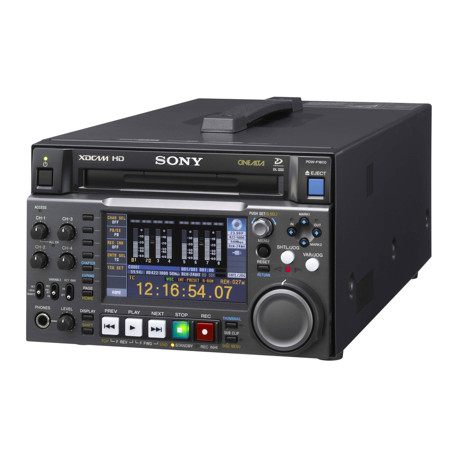
PROFESSIONAL DISC RECORDER
PDW-F1600
PDW-HD1500
The supplied CD-ROM includes operation manuals for the PDW-F1600/HD1500
Professional Disc Recorder (English, Japanese, French, German, Italian, Spanish and
Chinese versions) in PDF format.
For more details, see "Using the CD-ROM Manual" on page 16.
OPERATION MANUAL
1st Edition (Revised 4)
[English]
3282295070
Advertisement
Table of Contents

Related Manuals for Sony PDW-F1600


Summary of Contents for Sony PDW-F1600
- Page 1 PROFESSIONAL DISC RECORDER PDW-F1600 PDW-HD1500 The supplied CD-ROM includes operation manuals for the PDW-F1600/HD1500 Professional Disc Recorder (English, Japanese, French, German, Italian, Spanish and Chinese versions) in PDF format. For more details, see “Using the CD-ROM Manual” on page 16. OPERATION MANUAL [English] 1st Edition (Revised 4)
-
Page 2: Important Safety Instructions
This apparatus is provided with a main switch on the rear Important Safety Instructions panel. Install this apparatus so that user can access the main switch • Read these instructions. easily. • Keep these instructions. • Heed all warnings. • Follow all instructions. •... - Page 3 If you have questions on the use of the above Power Cord/ CAUTION Use of controls or adjustments or performance of procedures Appliance Connector/Plug, please consult a qualified service other than those specified herein may result in hazardous personnel. radiation exposure. WARNING Excessive sound pressure from earphones and headphones can cause hearing loss.
- Page 4 Pour les clients en Europe Le fabricant de ce produit est Sony Corporation, 1-7-1 Konan, CET APPAREIL DOIT ÊTRE RELIÉ À LA Minato-ku, Tokyo, Japon. Le représentant autorisé pour EMC et la sécurité des produits TERRE.
- Page 5 Vasen, darauf abgestellt werden. qualifiziertes Kundendienstpersonal. Für Kunden in Europa Solange das Netzkabel an eine Netzsteckdose Der Hersteller dieses Produkts ist Sony Corporation, 1-7-1 angeschlossen ist, bleibt das Gerät auch im ausgeschalteten Konan, Minato-ku, Tokyo, Japan. Zustand mit dem Stromnetz verbunden.
-
Page 6: Table Of Contents
Table of Contents Chapter 1 Overview Marks for Model-Specific Functions ..........11 Features..................11 Features of this unit ................11 System Configurations ..............15 Using the CD-ROM Manual ............16 Preparations ..................16 Reading the CD-ROM manual ............16 Chapter 2 Names and Functions of Parts Front Panel .................. - Page 7 Handling Discs................52 Discs used for recording and playback..........52 Notes on handling ................52 Write-protecting discs................53 Loading and unloading a disc .............. 53 Formatting a disc ................. 53 Chapter 4 Recording and Playback Recording..................54 Mixed recording of clips in different formats on the same disc ..54 Preparations for recording ..............
- Page 8 Selecting the information displayed on thumbnails ......81 Changing clip index pictures ............... 81 Checking clip properties..............82 Setting clip flags .................. 84 Locking (write-protecting) clips............85 Deleting clips..................85 Scene Selection (Clip List Editing) ..........87 What is scene selection?..............87 Creating and editing clip lists ..............
- Page 9 Recording Continuous Timecode with FAM and FTP Connections ................122 Chapter 7 Menus Menu System Configuration............123 Setup Menu .................. 123 Items in the basic menu ..............124 Basic menu operations............... 128 Items in the extended menu ............... 131 Extended menu operations..............146 Maintenance Menu ..............
- Page 10 Ancillary data in MXF files............... 178 General MXF metadata ..............178 Closed caption data ................179 Correspondence between Setting Items of the HKDV-900 and Setup Menu of This Unit............184 List of Supported USB Keyboards ..........185 Trademarks and Licenses............188 MPEG-4 visual patent portfolio license ..........188 MPEG-2 video patent portfolio license..........
-
Page 11: Chapter 1 Overview
The unit can be used as a player for video editing and program output, and as a recorder for nonlinear editing. For these applications, it can be connected to Sony nonlinear editors, monitors, and video equipment with HDSDI interfaces via its standard HDSDI I/O connectors. - Page 12 HD1500 When the PDBK-S1500 or PDBK-F1500 option is installed. you to use SD nonlinear editors and monitors for editing 2) MPEG HD is a registered trademark of Sony Corporation. 3) Playback only supported for 18 Mbps. and program output. Support for multiple frame frequencies...
-
Page 13: Filter Clips Function
small size, proxy AV data can be transferred quickly over • Select only clips that were recorded according to computer networks, easily edited in the field with laptop planning metadata, and use the Direct FTP function to computers , and readily used in a wide variety of transfer those clips to an external device. - Page 14 This function is available through simple operations on the GUI screen. Supports SNMP for maintenance and service This unit supports Sony’s SNMP-based remote maintenance and monitoring software. This software allows you to monitor the status of the hardware via a TCP/ IP network in real time, and to record the results in a status log.
-
Page 15: System Configurations
System Configurations DIGITAL AUDIO (AES/EBU) Professional Discs OUT/IN PDW-700 ANALOG AUDIO OUTPUT/INPUT • PFD23A • PFD50DLA HKDV-900 HKDV-900 video control unit PDW-1500 Sony BP-L80S/GL95 battery SDSDI HDSDI OUTPUT VIDEO INPUT CONTROL BKP-L551 battery EJECT adaptor RM-280 editing REMOTE controller PUSH SET(S.SEL) -
Page 16: Using The Cd-Rom Manual
Adobe Reader. In such a case, install the latest version you can download from the URL mentioned in “Preparations” above. Note If you have lost or damaged the CD-ROM, you can purchase a new one to replace it. Contact your Sony service representative. Using the CD-ROM Manual... -
Page 17: Chapter 2 Names And Functions Of Parts
Names and Functions of Parts Chapter Front Panel The names and symbols of buttons and knobs on the front Orange: Function when the button is operated with the panel are color coded according to function. SHIFT button held down. White: Function when the button or knob is operated Blue: Function related to thumbnail operations. -
Page 18: Key Inhi Switch
1 Audio level adjustment section access to the disc is completed before the unit switches to the standby state. 1 CH-1/ALL CH, CH-2 to CH-4 adjustment knobs Note CH-1 CH-3 While the ACCESS indicator is lit, do not turn off the POWER switch on the rear panel or disconnect the power ALL CH cord. - Page 19 3 Shuttle/jog/variable control section 1 V/MARK1 button and v/MARK2 button 2 IN indicator and OUT indicator 1 SHTL/JOG button 2 VAR/JOG button MARK1 3 Jog/shuttle transport indicators SHTL/JOG VAR/JOG 3 B/IN button and b/OUT button RESET MARK2 RETURN L/JOG a V/MARK1 button and v/MARK2 button When the THUMBNAIL indicator (see page 21) is lit, you can use these for thumbnail selection.
-
Page 20: Menu Button
4 Display/menu control section setup menu item 101 SELECTION FOR SEARCH DIAL ENABLE to “dial”). e Shuttle dial 5 RESET/RETURN button Turn this for playback in shuttle mode or variable speed 4 MENU button mode. Turn clockwise for forward direction playback, and 3 PUSH SET(S.SEL) knob counterclockwise for reverse direction playback. -
Page 21: Display Button
h DISPLAY button monitor connected to the unit. Press once more to return to the original display. Each press of this button switches between the basic operation display and video monitor display (see page 23). See “GUI screen operations” (page 75) for more This button is disabled unless either the basic operation information about how to use the thumbnail screens. -
Page 22: Play Button
5 Recording and playback control section button again with the SHIFT button held down. (The lit or unlit status of the STOP button does not change.) 1 PREV button Note 2 PLAY button 3 NEXT button This button flashes when setup menu item 105 REFERENCE SYSTEM ALARM is set to “on”... -
Page 23: Display Window
• The format of the recorded part of the disc does not match the system frequency settings of the unit. Display window Basic operation display 1 Audio input display/ Audio level meters 6 Disc information 2 Function menu 7 System information 3 Clip information 8 Format conversion 4 Recording format... -
Page 24: Function Menu
A Input signal display: Displays the audio input signal. All remaining clips or clip list playback time Display Input signal Total number of clips recorded on disc ANA-1 Analog audio Channel 1, 3 signal ANA-2 Channel 2, 4 PDW-HD1500 001/001 000:00 MIC-1 Input signal from Channel 1, 3... - Page 25 C Timecode generator mode: Displays the timecode Note source and generation method (preset or regenerate). Even if the background is blue, recording is not These are set with PRST/RGN and TCG on page P5 possible in the following cases. TC of the function menu (see page 51). •...
-
Page 26: Video Monitor Display
: Format conversion is being performed. Display Power status AC power (power-saving mode) See page 64 for more information about 1080/720 cross convert function. Battery (power-saving mode) i Reference signal Battery (power-saving mode/low) This displays the type of reference signal to which this unit is synchronizing. - Page 27 When you press the DISPLAY button, the display window changes to the video monitor display. A Audio level meters: LEVEL MT on page P2 AUDIO of the function menu decides whether the meter is to be displayed and on which side, left or right, it is displayed in the display window.
-
Page 28: Rear Panel
(D-sub 9-pin) setting for setup menu item 028. To control this unit from a controller or VTR supporting the RS-422A Sony 9-pin VTR protocol, connect the device See “Basic Operations of the Function Menu” (page 48) to this connector. for more information about the CHAR SEL settings. - Page 29 l SDSDI OUTPUT 1, 2 (SUPER) (SDI signal outputs See page 126 for more information about the setup menu item 028 HD CHARACTER. 1, 2 (superimpose)) connectors (BNC type) These output SDSDI format video/audio signals. To treat the input and output signals of these connectors as When the unit is shipped from the factory, audio signal non-audio signals, set the maintenance menu item M37: output is eight channels with no switching, and RP188...
-
Page 30: Microphone Settings
2 Analog audio signal input/output section See “Basic Operations of the Function Menu” (page 48) for more information. 1 ANALOG AUDIO INPUT 1, 2 connectors 3 Digital audio signal input/output section 2 ANALOG AUDIO OUTPUT 1, 2 connectors ANALOG AUDIO INPUT ANALOG AUDIO OUTPUT AUDIO MONITOR 1 DIGITAL AUDIO (AES/EBU) IN 1/2, 3/4... - Page 31 During recording: The timecode from the internal timecode generator or the timecode input to the TIME CODE IN connector When setup menu item 611 TC OUTPUT PHASE IN EE MODE is set to “muting”, no timecode is output. Rear Panel...
-
Page 32: Chapter 3 Preparations
This unit can be powered by AC power, DC power, or a operation manual for the battery charger. battery pack. For safety, use only the Sony battery packs listed below. Notes about battery usage Lithium-ion battery pack: BP-L80S, BP-GL95 • Before using the batteries, be sure to charge them fully with the special battery charger. -
Page 33: Initial Setup
Initial Setup This unit is shipped with the area of use, system frequency, recording format, and current date and time still unset. Therefore, you need to make initial setup settings before using the unit. (You cannot use the unit without setting it BP-GL95 up.) Once the unit has been set up, the settings are retained even... - Page 34 RETURN RETURN I N I T I A L SE TU P IN ITI AL SE TUP S Y S T E M FR EQ UE NC Y SE L EC T Pu sh F5 (SA VE) K ey! ! 1 0 80 / 50 i I N C / D EC : C T RL .K NO B C A N C E L &...
-
Page 35: Front Panel Tilt Mechanism
To change the angle of the front panel Front Panel Tilt To change the angle to position 2 from position 1, pull the front panel out to position 2. Mechanism To change the angle to position 1 from position 2, first unlock the front panel by pulling it all the way out to the return position. -
Page 36: Connections And Settings
Production of some of the peripherals and related devices PDW-HD1500 described in this chapter has been discontinued. For advice about choosing devices, please contact your Sony dealer or a Sony sales representative. Laptop computer Connections for using PDZ-1 Proxy Browsing Software... -
Page 37: Connections For Cut Editing
Use of a shielded cable is recommended. PDW-F1600 or PDW- HD1500 (this unit) Laptop computer To S400 connector i.LINK cable (not supplied) Connections for cut editing The following figure shows a cut editing system comprising this unit as a player. When making the connections, also refer to the manuals provided with the equipment to be connected. - Page 38 1: 75Ω coaxial cable (not supplied) HD video monitor 2: 9-pin remote control cable (not supplied) To HDSDI input connector HDSDI OUTPUT 2 (SUPER) PDW-F1600 or POWER AC IN DC IN 12V= PDW-HD1500 REMOTE (this unit, player) ANALOG AUDIO INPUT ANALOG AUDIO OUTPUT AUDIO MONITOR REF.VIDEO...
- Page 39 Editing Control Unit Settings When connecting an editing control unit (BVE-700/700A/ 2000) to use with this unit, set VTR constants as follows. F1600 System VTR CONSTANT frequency 59.94i/ 59.94P/ 29.97P 50i/50P/25P 23.98P a) This is 15 when maintenance menu item M393: AUDIO DSP is set to “AGC/limiter”.
- Page 40 1: 75Ω coaxial cable (not supplied) HD video monitor 2: 9-pin remote control cable (not supplied) To HDSDI input connector HDSDI OUTPUT 2 (SUPER) PDW-HD1500 (player) DC IN 12V= POWER AC IN REMOTE ANALOG AUDIO INPUT ANALOG AUDIO OUTPUT AUDIO MONITOR REF.VIDEO INPUT DIGITAL AUDIO (AES/EBU)
-
Page 41: Using The Editing Functions Of The Recorder (Controlling Through Remote(9P) Connector)
Using the editing functions of the HDW-M2000 (recorder) Settings on this unit setting recorder (controlling through REMOTE 1 (9P) button: Remote control switch: REMOTE(9P) connector) Unlit REMOTE (see page 18) Setup menu item 214 The following figure shows a cut editing system REMOTE INTERFACE: 9PIN comprising this unit as a player, and an HDW-M2000/ For details of HDW-M2000/M2000P settings, refer to the... -
Page 42: Synchronization Reference Signals
Synchronization Reference Signals The synchronization reference signal generator of this unit setting of OUT REF on page P6 REF of the function menu, synchronizes to a reference signal input to the REF. and on the type of the selected input signal. Video output VIDEO INPUT connector or to a video input signal. -
Page 43: Setting System Frequency
Setting System Setting Timecode Frequency There are the following four ways of recording timecode: Internal Preset mode: This records the output of the This unit can record and play back video at the system internal timecode generator, set beforehand to an frequencies of 59.94i, 50i, 29.97P, 25P, and 23.98P initial value. -
Page 44: Setting User Bits
Press the TCG SET function button (F5). Select UB by pressing the CNTR SEL function button (F4) in step 1 of “Setting an initial timecode value” and carry The first digit of the time data display starts flashing. out steps 2 to 5. Settings are made in hexadecimal (0-9, A-F). -
Page 45: Superimposed Text Information
Synchronizing with embedded LTC input to the Superimposed Text SD/HDSDI INPUT connector Information Input an HDSDI signal containing embedded LTC to the SD/HDSDI INPUT connector, and a reference video signal to the REF. VIDEO INPUT connector. The video signal output from the COMPOSITE OUTPUT Make the following settings on page P5 TC of the 2 (SUPER) connector, SDSDI OUTPUT 2 (SUPER) function menu. - Page 46 a Type of time data Display Operation mode Display Meaning Block A Block B Counter data C.STANDBY OFF Standby off mode TC reader timecode STOP Stop mode TC reader user bits data C.STOP Stop mode TCR. VITC reader timecode NEXT xxx Cuing up to the first frame of the UBR.
- Page 47 To prevent playback conditions from Display Name Description deteriorating Red condition The playback condition has Pay attention to the following points when handling discs. deteriorated. There are no read • Do not open disc cartridges and touch discs directly with errors, but you should take the your hands.
-
Page 48: Basic Operations Of The Function Menu
button again while the page P2 is displayed switches the Basic Operations of the page to P8. To clear the function menu from the screen Function Menu Press the DISPLAY button to switch to the video monitor display. The function menu provides access to frequently used To change the setting of a function menu settings, such as input video signal selection and timecode item... -
Page 49: P1 Video Page
Item Setting Item Setting F4: CNTR SEL Selects the type of time data to display in F5: HUE/CHRM Sets the hue (chroma phase). the time data display area. PRESET: Set the hue (chroma phase) to TC: Timecode a preset value, regardless of manual COUNTER: Elapsed recording or setting. -
Page 50: P4 Audio Page
Item Setting Item Setting F5: SPEAKER Enables or disables output from this F6: A8 INPUT Selects the audio input signal to assign unit’s speaker. to audio channel 8. OFF: Do not output SDI: Audio signal embedded into SDI ON: Output signal ANALOG2: Analog 2 audio signal F6: LEVEL MT... -
Page 51: P5 Tc Page
P5 TC page P6 REF page Item Setting Item Setting F1: TCG Selects the timecode signal to which the F1: OUT REF Selects the reference signal for the internal timecode generator output signals of this unit. synchronizes. REF: Use the signal input to the INT: Follow the initial value set from the REF.VIDEO INPUT connector as the control panel or remotely from the... -
Page 52: Handling Discs
148). • PFD50DLA (capacity 50.0 GB) • “DISABLE” is always selected when the unit is powered off and then on 1) Professional Disc is a trademark of Sony Corporation. again, regardless of the previous setting. Notes (Unassigned function button) •... -
Page 53: Write-Protecting Discs
• If condensation forms, allow ample time to dry before MODE KEY ENABLE DURING RECORDING to use. “stop”. Write-protecting discs Formatting a disc To protect the content recorded on the disc from accidental Unused discs are formatted automatically when they are erasure, move the Write Inhibit tab on the lower surface of loaded into this unit. -
Page 54: Chapter 4 Recording And Playback
Recording and Playback Chapter Frame frequency groups Recording The system frequencies supported by this unit are divided into frame frequency groups, as shown in the following table. This section describes video and audio recording on the Frame frequency group System frequency unit. -
Page 55: Carrying Out Recording
Timecode and user bits settings: See “Setting Timecode” Recording starts. (page 43). Selection of time data to display: Select with CNTR SEL To stop recording, press the STOP button. on HOME page of the function menu. If the disc becomes full Selection of audio channels to monitor: Select with Recording stops and the message “ALARM DISC END.”... -
Page 56: Continuing Recording While Exchanging Discs (Disc Exchange Cache Function)
MAINTENANCE connector, you can record shot marks When recording on the current disc ends, the disc is from Shot Mark0 up to Shot Mark9 by pressing the 0 to 9 ejected. Until the next disc is inserted, the unit records keys on the numeric keypad. -
Page 57: Recording With The Hdsdi Remote Control Function
• The Disc Exchange Cache function cannot be enabled operation according to the embedded REC or STOP when the Live Logging function is set to Live View command. mode. Exchanging discs Even during recording, it is possible to eject discs by pressing the EJECT button on the front panel. -
Page 58: Using The Live Logging Function
Do one of the following to stop the Clip Continuous Rec In PDZ-1, you can do the following during Live Logging. function. (A new clip will be generated the next time you • Display logging AV data (only in Live View mode) start recording.) •... - Page 59 system to perform a full salvage of the disc. As the other disc, set the Write Inhibit tab to enable recording, system, use the PDW-F800 or PDW-700. and then insert the disc again. If REC INH on • The following alarm message (see page 162) may HOME page of the function menu is set to “ON”, set appear when you insert a disc: it to “OFF”...
-
Page 60: Linear Editing
- HD422 clips recorded with the Interval Rec, Picture Linear Editing Cache, Disc Exchange Cache, or Slow & Quick Motion functions - HD422 clips that have been partially transferred by an FTP or FAM connection Overview - Clips for which disc defects have been detected - Clips for which errors have been detected, such as You can perform the following types of editing on when the unit’s primary power was turned off during... -
Page 61: Connections
Model number Capacity Data transfer rate Item Setting (writing) Audio digital signal With the maintenance menu item M39: PFD23A 23.3 GB 2.4 times normal processor OTHER CONFIG >M393: AUDIO DSP, select “linear edit”. PFD50DLA 50.0 GB Video input signal Select the video input signal with V INPUT on page P1 VIDEO of the Note function menu. -
Page 62: Editing Operations
To set up mixing of audio input signals To confirm the setting and return to the input channel selection screen By making setup menu settings, you can perform the Press the PUSH SET(S.SEL) knob. following kinds of audio mixing. • Mixing of audio input signals. To exchange input channels •... -
Page 63: Playback
Requirements for use of editing controllers Playback Model name Requirement RM-280 Software version: 2.04 or higher On this unit, set setup menu item 501 This section describes playback of video and audio on the STILL TIMER to 1 min (1 minute) or unit. -
Page 64: Playback Operation
SD up convert function VITC 00:59:59:23 By installing the PDBK-S1500 option, you can output HD PDT 00:59:59:29 while playing discs recorded as SD. You can superimpose the 30-frame timecode after pulldown on an external monitor. To do so, set setup menu HD down convert function item 005 DISPLAY INFORMATION SELECT to “time data only”. - Page 65 See page 175 for an overview of the PDZ-1 software and information about how to install it. EJECT You can also delete and modify essence marks from the MARK1 Thumbnail Menu of the chapter thumbnail screen (see PUSH SET(S.SEL) ACCESS CH-1 CH-3 page 77).
-
Page 66: Playback Operations Using Thumbnails
Playback in shuttle mode In shuttle mode, you can control the speed of playback by EJECT the angular position of the shuttle dial. The range of playback speed is ±20 times normal speed or maximum PUSH SET(S.SEL) MARK1 ACCESS CH-1 CH-3 speed (as selected by an extended menu setting). - Page 67 See “Thumbnail Operations” (page 76) for more information about thumbnail operations, and “Scene Selection (Clip List Editing)” (page 87) for more information about the scene selection function. Playback...
-
Page 68: Chapter 5 Operations In Gui Screens
Operations in GUI Screens Chapter Overview You can perform scene searches, play the searched scenes, (The GUI screens can display European languages, and select scenes (edit clip list) in Graphical User Interface Japanese, Korean, Simplified Chinese, and Traditional (GUI) screens. The GUI screens are your gateways to discs Chinese for clip names and titles.) and the data saved on discs. -
Page 69: Information And Controls In Thumbnail Screens
Clip thumbnail screen Clip playback screen Clip:C0006 006/040 TC 00:23:00:25 TC 00:23:40:07 TC 00:24:45:11 TC 00:25:06:14 TC 00:25:49:23 TC 00:26:22:10 TC 00:27:19:04 TC 00:27:51:09 TCR 00 : 23 : 00 . 26 TC 00:28:06:09 TC 00:28:22:02 TC 00:23:34:18 TC 00:23:54:22 STILL 30 NOV 2005 13:38 0:00:10:23... -
Page 70: Clip Thumbnail Screen
e Recording format Area of use Select Font Displayable The recording format of the selected clip is displayed as a setting setting languages combination of the following information. UC (for regions European English/European • Video format logo outside Japan) Alphabet languages •... -
Page 71: Expand Thumbnail Screen
f Total duration page 81). The factory default selection is the timecode of the first frame or the timecode of the thumbnail frame. Displays the total duration of all sub clips in the clip list. f Lock icon Expand thumbnail screen This icon appears when the clip is locked (protected) (see This screen displays thumbnails of equally sized divisions page 85). -
Page 72: Displaying Menus
Essence mark thumbnail screen Note This screen displays thumbnails of the specified essence Shot marks can be set by the user during recording and mark, found by searching all clips on the disc. playback. They can be deleted and moved. Essence marks other than shot marks are set automatically. - Page 73 To display the Thumbnail Menu Clip thumbnail screen To display the Thumbnail Menu, press the MENU button with a thumbnail screen displayed. To return to the original screen, press the MENU button again, or press the RESET/ RETURN button. EJECT MARK1 PUSH SET(S.SEL) ACCESS...
- Page 74 Item Operation/Setting Planning Metadata Properties Display the properties of the currently loaded planning metadata. Clear Planning Metadata Clear the currently loaded planning metadata from the unit’s memory. Lock or Delete All Clips Sub-Item Lock All Clips Lock all clips. Unlock All Clips Unlock all clips.
-
Page 75: Gui Screen Operations
GUI screen operations EJECT PUSH SET(S.SEL) MARK1 ACCESS CH-1 CH-3 EJECT MENU MARK2 SHTL/JOG ALL CH VAR/JOG CH-2 CH-4 RESET CHAPTER PUSH SET(S.SEL) MARK1 RETURN ACCESS EXPAND CH-1 CH-3 VARIABLE KEY INHI PAGE MENU PRE- MARK2 LOCAL SHTL/JOG REMOTE HOME ALL CH VAR/JOG CH-2... -
Page 76: Thumbnail Operations
To scroll hidden parts of the string into Thumbnail Operations view When a b or B mark is displayed for an item, you can press the B/IN or b/OUT button to scroll the display by You can use thumbnail screens to display clip information one character for each press. -
Page 77: Searching With Thumbnails
Press the PUSH SET(S.SEL) knob at the new position. first frame in each block. This is a quick and efficient way to review the selected clip and search for target scenes. The thumbnail at the position indicated in the small You can specify 12, 144, or 1728 divisions. - Page 78 See “To set shot marks” (page 55) for more information. Display the Thumbnail Menu. See page 75 for more information about thumbnail screen Select Move Essence Mark. operations. The Move Essence Mark screen is displayed. In the clip thumbnail screen, select the thumbnail of a clip with chapters set.
-
Page 79: Playing The Scene You Have Found
To search for a thumbnail position and cue If planning metadata with user-defined essence mark has been loaded it up You can select user-defined essence marks (see page 96). See page 75 for more information about GUI screen operations. Select the thumbnail that you want to cue up. Clip:C0010 010/041 TC 00:23:00:25... - Page 80 • Select clips in a certain video format from a disc that contains clips in different video formats. • Select clips that have been set “NG” as a clip flag, and delete all of those clips in one operation. • Select only clips that have been recorded on the basis of a specified planning metadata entry, and transfer those clips to an external device using the Direct FTP function (see page 99).
-
Page 81: Selecting The Information Displayed On Thumbnails
Sequence Number: Thumbnail sequence number Item name Function Return to Upper Menu: Returns to the Thumbnail Lock or Delete All Filtered Unlock all of the filtered clips. Menu Clips >Unlock All Filtered Clips The selected information will appear at the bottom of Lock or Delete All Filtered Delete all of the filtered clips. -
Page 82: Checking Clip Properties
To select index pictures by using the expand and chapter functions After using the expand function (see page 77) or chapter function (see page 77) to find a frame, you can set that frame as the index picture of the clip. The following example explains how to do so from the expand thumbnail screen. - Page 83 • Some symbols cannot be used in clip names. The keys You return to the Clip Properties screen, and the for those symbols are disabled when you are editing a results of the editing are reflected in the clip clip name. information.
-
Page 84: Setting Clip Flags
set to “Korean”, “Simplified Chinese”, or “Traditional USB mouse functions Chinese”. You can use the mouse to move the cursor on the software keyboard. You can also left click on a key to enter the The keyboard icon on the software keyboard is highlighted character for that key. -
Page 85: Locking (Write-Protecting) Clips
Select the clip flag that you want to set (OK/NG/KP Select Lock or Delete All Clips, and then select Lock (KEEP)). All Clips. A message appears asking you to confirm locking all A clip flag icon (see page 70) appears for clips that clips. - Page 86 To delete all clips Notes • Clips cannot be deleted when the write inhibit tab of the Display the Disc Menu. disc is set to the recording disabled position, or when REC INH in HOME page of the function menu is set to Select Lock or Delete All Clips, and then select Delete All Clips.
-
Page 87: Scene Selection (Clip List Editing)
Sub clips (clips in clip lists) Scene Selection (Clip List Clips (or parts of clips) that have been added to a clip list are called “sub clips”. Sub clips are virtual editing data that Editing) specify ranges in the original clips. You can use them without modifying the original data. -
Page 88: Creating And Editing Clip Lists
To add sub clips To play a clip list, insert a disc into the unit, load the clip list that you want to play, and press the PLAY button. You can add sub clips to clip lists from with the clip Clips are played according to the data in the clip list. - Page 89 To check the addition results the location where the currently selected sub clips will Move the cursor. be inserted. Press the RESET/RETURN button. To display the total duration after addition of the selected clips This returns you to the Clip thumbnail screen. Press the SHIFT button.
- Page 90 To delete the In point or Out point Press the PUSH SET(S.SEL) knob. Press the RESET/RETURN button with the B/IN or The sub clips are moved to the I cursor position. b/OUT button held down. Repeat steps 1 to 5 as required. With the SHIFT button held down, press the PUSH SET(S.SEL) knob.
- Page 91 To cue up the In point or Out point To start play from the start of the clip list Display the Thumbnail Menu, select Cue up Inpoint or Select the thumbnail of the first sub clip. Cue up Outpoint, and then press the PUSH SET(S.SEL) knob.
-
Page 92: Managing Clip Lists
To reset the timecode to 00:00:00:00 Date(Newest First): Sort by date and time of clip list Select Reset to Zero in the Thumbnail Menu, and then creation, newest first. press the PUSH SET(S.SEL) knob. Select the desired clip list name, and then press the To preset the frequently used timecode PUSH SET(S.SEL) knob. - Page 93 A list of clip lists appears. Disc Menu Select the clip list that you want to delete, and then Load Clip List Name & Date/Sorted by Name press the PUSH SET(S.SEL) knob. DVD og BI... 08 AUG2007 11:50 E0003 03 AUG2007 17:51 A message appears asking you to confirm the deletion.
-
Page 94: Disc Operations
Using planning metadata Disc Operations Planning metadata is a file that contains metadata about the clips to be shot and recorded. To use planning metadata, you will need to save a file in Checking disc properties advance in the specified location of a media, and insert the media into this unit. - Page 95 When a b or B mark is displayed for an item, you can Select the desired planning metadata file, and then press the PUSH SET(S.SEL) knob. press the B/IN or b/OUT button to scroll the display by one character for each press. The selected planning metadata file is loaded into the The V/MARK1 and v/MARK2 buttons scroll the unit’s memory, and the Planning Metadata Properties...
-
Page 96: Checking User-Defined Essence Marks
To cancel the format Checking user-defined essence Select Cancel, and then press the PUSH SET(S.SEL) marks knob. You can display the names of user-defined Shot Mark0 to To continue by formatting another disc Shot Mark9 essence marks in planning metadata (UTF-8 Exchange the disc, select OK, and then press the format, maximum 32 bytes). - Page 97 Start the browser on the computer, and enter “http://” + IP_address_of_this_unit + “/” in the address bar of the browser, and then press the Enter key. For example, if the IP address of this unit is “192.168.001.010”, enter “http://192.168.1.10/”. If the connection succeeds, you will be prompted to enter a user name and a password.
- Page 98 To download high-resolution clip data (HIGH resolution file), proxy AV data (LOW resolution file), or metadata (Clip NRT metadata), click the FTP Download or HTTP Download button to the right of the item that you want. Then click “Save” in the dialog that appears and specify the save destination.
-
Page 99: Transferring Clips (Direct Ftp Function)
Transferring Clips (Direct FTP Function) You can transfer clips (MXF files) between this unit and Transfer direction Transfer target Function external devices over a network. This unit has an Direct Download One clip FTP function, which allows you to connect to any XDCAM device or computer with an FTP server function Note and transfer files with a few simple operations in the GUI... -
Page 100: Uploading Clips
To enable the UPnP function To transfer while preserving the UMID of the The UPnP (universal plug and play) function allows transfer source clips devices to be easily connected to networks. The following Check the “UMID Unchanged” option. XDCAM devices support UPnP. •... - Page 101 be enabled when you power the unit off and then on Item Setting again.) The Select Host Discovered via UPnP screen appears. Host Name Host name or IP address. (If this is a host name, a DNS server must be (Some time may be required before the search for available on the connected network.
- Page 102 To check the connection on the remote host side If the remote host is an XDCAM device, check that the “NETWORK!” has appeared in the display or other status display location. The following table lists the various stages that appear in the connection status screen and describes the corresponding processing.
-
Page 103: Downloading Clips
See page 75 for information about thumbnail screen operations. Display the Disc Menu. Select Download Clip via Direct FTP, and then press the PUSH SET(S.SEL) knob. The Select Remote Host screen of the Download Clip via Direct FTP command appears. To upload part of a clip You can select part of a clip in the expand thumbnail screen or the chapter thumbnail screen and upload that... -
Page 104: Copying Clips Directly Between Xdcam Devices
The Select Remote Host screen appears. Copying clips directly between XDCAM devices Select “Hosts Discovered via UPnP”, and then press the PUSH SET(S.SEL) knob. In the field or another environment where the devices are The detected connection destination device (the PDW- not connected to a network, you can copy (upload) clips HD1500) appears in the Select Host Discovered via between XDCAM devices by connecting them directly. -
Page 105: Shortcut List
Shortcut List You can access many functions from the buttons, without Note displaying a menu (shortcut operations). The same shortcut may access different functions, Shortcuts are available for the following functions. The depending on the screen that is active when it is executed. plus sign (+) indicates that one button is held down while another is pressed, for example “SHIFT + RESET/ RETURN”. -
Page 106: Chapter 6 File Operations
File Operations Chapter Overview A remote computer can be connected to this unit and used to operate on recorded data which has been saved in data files, such as video and audio data files. There are two ways to connect a remote computer. •... -
Page 107: File Operation Restrictions
(Continued) File operation restrictions This section explains which operations are possible on Write: Write data sequentially from the start to the end of files stored in each directory. the file. When required, the following operation tables distinguish Partial write: Write data to a part of the file only. reading and writing from partial reading and writing. -
Page 108: Clip Directory
• The directories in the root directory (Clip, Edit, Sub, Notes UserData, General, and PROAV) cannot be deleted or • Directories cannot be created in the root directory. renamed. Clip directory File name Content Operations Read/Partial read Write/Partial write Rename Create Delete b), c) Clip file created by recording (MXF .MXF... -
Page 109: Sub Directory
File name Content Operations Read/Partial read Write/Partial write Rename Create Delete Metadata file generated automatically M01.XML when E*E01.SMI file is created. *: 0001 to 0099 Other files Files other than the above – – – a) The “E*” part can be changed to a user-defined name. f) When an E*E01.SMI file is created, an E*M01.XML file with the same b) Only files which can be written by XDCAM. -
Page 110: Assigning User-Defined Clip Titles
• Deletion and renaming of directories Notes C0020.MXF • The maximum number of files that can be created on a C0002.MXF disc is 5,000 for single-layer discs and 6,000 for dual- C0001.MXF layer discs (both including directories). TITLE00020 • File names and directory names can use letters, numbers, TITLE00002 and symbols from the Unicode 2.0 (UTF-8) character TITLE00001... -
Page 111: Assigning User-Defined Clip And Clip List Names
Turn the PUSH SET(S.SEL) knob to move the asterisk Clips: C0001.MXF to C9999.MXF (*) on the left of the menu items to the item you want Clip lists: E0001E01.SMI to E0099E01.SMI to select, and press the knob. This unit can handle clips and clip lists with user-defined names as well as names in the standard format. - Page 112 Turn the PUSH SET(S.SEL) knob to select “title”, and press the knob. Press the SAVE function (F5) button. C0001.MXF The same name will now be given to newly recorded clips. To use clips and clip lists with user-defined TITLE00001 names over FAM and FTP connections Carry out steps 2 to 5 of “To assign clip names on this When the “AUTO NAMING”...
-
Page 113: File Operations In File Access Mode (For Windows)
Making FAM connections File Operations in File Access Mode (for If there is a disc loaded in this unit, put the unit into the following state. Windows) • Recording, playback, search and other disc operations (see page 54): Stopped • THUMBNAIL button (see page 21): Off File access mode operating environment •... -
Page 114: Operating On Files
• Windows XP: “Sony XDCAM PDW-****** IEEE Operating on files 1394 SBP2 Device” (******: “F1600” or “HD1500”) is deleted from the “Hardware devices” Start Explorer. list. • Windows Vista: A message appears to inform you Check that a drive letter has been assigned to this unit. -
Page 115: File Operations In File Access Mode (For Macintosh)
Connect the (i.LINK) S400 connector on this unit to File Operations in File the i.LINK (IEEE1394) connector on the remote computer, using an i.LINK cable (see page 36). Access Mode (for When a disc is inserted into this unit, the remote Macintosh) computer recognizes this unit as a removable disc. -
Page 116: Exiting File Operations
Exiting file operations FTP File Operations Proceed as follows. File operations between this unit and a remote computer Note can be carried out by the File Transfer Protocol (called Do not disconnect the cable before performing steps 1 and FTP below). Preparations Eject the disc by clicking the eject button to the right of the icon for this unit in the Finder, or by dragging... -
Page 117: Command List
If the connection times out Note This unit terminates FTP connections if no command An FTP client that supports UTF-8 is required to use is received within 90 seconds of the last command. If Unicode characters other than ASCII characters. this occurs, log out (see the next section) and repeat Command prompt FTP commands do not support UTF-8. - Page 118 Input example: STRU F PORT Specifies the IP address and port to which this unit should connect for the next file transfer (for data transfer from this MODE unit). Specifies the transfer mode. Command syntax: PORT <SP> <h1,h2,h3,h4,p1,p2> Command syntax: MODE <SP> <mode-code> <CRLF> <CRLF>...
- Page 119 • No specification: A list of the file names only in the current Command syntax: RNFR <SP> <path-name (before directory. change)> <CRLF> RNTO <SP> <path-name (after change)> <CRLF> The wildcard characters “*” (any string) and “?” (any Input example: RNFR General/info.txt character) may be used in <path-name>.
- Page 120 HELP Displays a list of the commands supported by this unit, or Deletes a directory. an explanation of the specified command. Command syntax: HELP <SP> <command-name> Note <CRLF> Directories can be deleted only in the General directory. The following data is transferred, depending on whether a For details, see “File operation restrictions”...
- Page 121 Input example: SITE REPF Clip/C0001.MXF 5 150 SITE UMMD (Transfer C0001.MXF. Body data is transferred only When a C*.MXF file is sent with the STOR command, the from frame 6 to frame 150.) copy source UMID is saved if this command is invoked immediately before the STOR command.
-
Page 122: Recording Continuous Timecode With Fam And Ftp Connections
Input example: SITE TCPR 00050001 Recording Continuous (The starting timecode is preset to 01:00:05:00.) Timecode with FAM and FTP Connections When you are connected to the unit by FAM or FTP, you can create new clips with timecode that is continuous with the timecode of the last frame of the last clip on the disc. -
Page 123: Menu System Configuration
Menus Chapter Menu System Setup Menu Configuration The setup menu system of this unit comprises the basic setup menu and extended setup menu. The settings for this unit use the following menus. Basic menu Setup menu This menu is used to make settings relating, for example, The setup menu system of this unit comprises the basic to the following. -
Page 124: Items In The Basic Menu
Item group Function Refer to Item group Function Refer to Items Settings relating to the page 136 Items Settings relating to control page 131 600 to 650 timecode generator 100 to 199 panels Items Settings relating to the page 137 Items Settings relating to the remote page 133... - Page 125 Item number Item name Settings DISPLAY INFORMATION Determine the kind of text information to be output from the COMPOSITE SELECT OUTPUT 2 (SUPER) connector, the SDSDI OUTPUT 2 (SUPER) connector, or the HDSDI OUTPUT 2 (SUPER) connector. T&sta (time data & status): Time data and the units status. T&UB (time data &...
- Page 126 Item number Item name Settings SYSTEM FREQUENCY Specify whether to enable switching the system frequencies (59.94i, 59.94P, SELECT MENU 29.97P, 50i, 50P, 25P, 23.98P). off: Do not enable switching the system frequencies. on: Enable switching the system frequencies. For details about switching the system frequencies, see page 43. Note Settings for both basic and extended menu items are saved separately for different system frequencies.
- Page 127 Item number Item name Settings STORED OWNERSHIP Specify whether to enable changing UMID ownership information settings (COUNTRY, ORGANIZATION and USER). off: Do not enable. on: Enable. See “Using UMID Data” (page 176) for more information about UMID. RECORDING FORMAT Set the recording format. HD422: HD422 420HQ: HD420HQ 420SP: HD420SP...
-
Page 128: Basic Menu Operations
Item number Item name Settings SAVE SETUP BANK-1 Set to “on” to save current menu settings to menu bank 1. SAVE SETUP BANK-2 Set to “on” to save current menu settings to menu bank 2. SAVE SETUP BANK-3 Set to “on” to save current menu settings to menu bank 3. RESET SETUP MENU Set to “on”... -
Page 129: Default Settings
Turning the PUSH SET(S.SEL) knob while holding Menu control Functions down the SHIFT button increases the increment of buttons adjustment. Function buttons RETURN: Goes up one level. F1 to F6 SELECT: Selects an item. To change other settings, press the PUSH SET(S.SEL) (The function to UP: Skips back 100 or 50 items in the be displayed... - Page 130 To return all settings to their factory default Turn the PUSH SET(S.SEL) knob so that the “*” mark settings appears next to the item you want to hide or display in the setup menu. Press the MENU button to display the setup menu. SE TUP C UST OMI ZE Press the RESET/RETURN button.
-
Page 131: Items In The Extended Menu
Items in the extended menu The following tables show the items in the extended menu. • The values in the Settings columns are the values which • Item names are the names which appear on an external appear in the time data display area. (The values may monitor to which the output of the COMPOSITE appear in a different format on an external monitor. - Page 132 Menu items in the 100s, relating to the control panels Item number Item name Settings KEY INHIBIT SWITCH EFFECTIVE Select which buttons can be operated when the KEY INHI switch is set to AREA “ON”. The following sub-items control different sets of buttons independently.
- Page 133 Menu items in the 100s, relating to the control panels Item number Item name Settings REC MODE Select the recording mode. normal: Normal recording mode D.EXC (disc exchange cache): Disc Exchange Cache mode C.REC (clip continuous rec): Clip Continuous Rec mode GUI OPERATION Select whether to disable the display of the Thumbnail Menu and Disc Menu when this unit is in any mode other than stop mode.
- Page 134 Menu items in the 200s, relating to the remote control interface Item number Item name Settings LIVE LOGGING MODE Specify the Live Logging operation mode. off: Disable the Live Logging function. live mode: Select Live mode. Supported operations are metadata editing only.
- Page 135 Menu items in the 300s, relating to editing operations Item number Item name Settings [F1600] Select methods for setting the edit presets of the digital audio channels ANALOG AUDIO EDIT PRESET CH5 to CH8 of this unit. Make these settings when using an editor REPLACE FOR CH5 (PVE-500, BVE-600, etc.) or remote control unit without a function to control digital audio edit presets.
- Page 136 Menu items in the 600s, relating to the timecode, metadata, and UMID Item number Item name Settings VITC POSITION In 59.94i/59.94P/ Select the line into which to insert VITC signals (SD output) 29.97P mode 12H ... 16H ... 20H: Any line from line 12 through line 20. SEL-1 Notes •...
- Page 137 Menu items in the 600s, relating to the timecode, metadata, and UMID Item number Item name Settings Select whether or not the time code is automatically regenerated. REGEN CONTROL MODE auto(assem & insert)edit: In automatic editing carried out in either assemble mode or insert mode with this unit as the recorder, regardless of the settings of F1 (TCG) and F2 (PRST/RGN) in function menu page 5, the time code generator regenerates...
- Page 138 Menu items in the 600s, relating to the timecode, metadata, and UMID Item number Item name Settings UMID HD VANC LINE Specify the HDSDI signal VANC line into which the UMID should be inserted. 9H to 17H to 20H (59.94i, 50i, 29.97P, 25P, 23.98P mode) 9H to 17H to 25H (59.94P, 50P mode) Note The output VANC line during playback follows the setting for recording.
- Page 139 Menu items in the 700s, relating to video control Item number Item name Settings BLANK LINE SELECT Switch blanking of the video output signal on or off for individual lines in the vertical blanking interval. Sub-Item The Y/C signal and odd/even fields are blanked simultaneously. ALL LINE - - -: Specify the blanking for each line separately.
- Page 140 Menu items in the 700s, relating to video control Item number Item name Settings Set the video setup amount to be added to the composite output signal (in VIDEO SETUP REFERENCE 59.94i/59.94P/29.97P mode only). Sub-item OUTPUT In 59.94i/59.94P/ Add the setup level selected by this item to the output signal. LEVEL 29.97P mode (UC) 0.0%, 7.5%...
- Page 141 Menu items in the 700s, relating to video control Item number Item name Settings WIDE MODE Specify whether to record and play back with the addition of wide picture information. Sub-Item Select whether to save wide picture information to the disc when INPUT recording.
- Page 142 Menu items in the 800s, relating to audio control Item number Item name Settings AUDIO OUTPUT PHASE Set the output timing of digital audio playback signals (HDSDI, SDI, AES/ EBU only), with 80H as a reference position. Output timing is earlier for values smaller than 80H and later for values greater than 80H.
- Page 143 Menu items in the 800s, relating to audio control Item number Item name Settings AUDIO INPUT LEVEL Select the analog audio input source. Note Sub-item To display this item on the PDW-F1600 or PDW-HD1500 with the PDBZ- UPG02 Software Upgrade Key installed, set maintenance menu item M393: AUDIO DSP to “AGC/limiter”.
- Page 144 Menu items in the 900s, relating to digital process Item number Item name Settings Select whether to use auto squeeze mode. AUTO SQUEEZE off: Do not use. on: Use. DOWN CONVERTER MODE (DC) Select the down-converter mode. crop: Select the edge-crop mode. l-box: Select the letter box mode.
- Page 145 Menu items in the 900s, relating to digital process Item number Item name Settings Select the source picture to use in converting SD to HD. UP CONVERTER PROCESS (UC) FIELD: Use field pictures. ADAPTIVE: Frame or field is selected automatically. Adjust the up-converter image enhancer, the sharpness of edge DETAIL GAIN (UC) enhancement.
-
Page 146: Extended Menu Operations
Menu items in the 900s, relating to digital process Item number Item name Settings IMAGE ENHANCER (INPUT UP Set up the operation of the up converter image enhancer for SD input, CONVERTER) separately from the settings for playback (menu items 950 to 959). Sub-Item pb: While SD signals are input, make the behavior of the image ENH SETTING... - Page 147 M A I N T E N A N C E M E N U M 0 : C H E C K M 1 : A D J U S T M 2 : S E R V I C E S U P P O R T M 3 : O T H E R S M 4 : S E T U P M A I N E N A N C E M 5 : N E T W O R K...
-
Page 148: Maintenance Menu
Maintenance Menu Items in the maintenance menu The following tables show the items in the maintenance • The values in the Settings columns are the values which menu. appear in the time data display area. (The values may • Item names are the names which appear on the video appear in a different format on an external monitor. - Page 149 M3: OTHERS: Other setting items Item Setting M38: F-KEY For details, refer to the Maintenance Manual. CONFIG M380: HOME2 Assign a function menu item to page HOME2 of the function menu as a user setting. M381: PAGE8 ASSIGN Assign a setup menu item to page P8 of the function menu as a user setting. M382: PAGE8 NAME Specify the name of a setup menu item assigned with M381: PAGE8 ASSIGN.
- Page 150 M3: OTHERS: Other setting items Item Setting M3B: VANC RX M3B0: VANC RX For setting HDSDI VANC data input parameters PARAMETER PACKET This setting is required for recording and playback of closed captions. For details, see page 178. Notes • In 59.94i, 50i, 29.97P or 25P mode, selecting the line also selects the corresponding line in the second field (for example, if line 9 is selected, line 527 is also selected for VANC packet reception).
- Page 151 M4: SETUP MAINTENANCE: Items relating to the setup menu Item Setting M46: MENU M461: MENU Displays the status of the menu bank where the current menu settings are stored. DATA STATUS CONTROL DISPLAY M462: SAVE Select whether to temporarily back up (save) setup menu settings before operations such as MENU DATA software upgrades.
-
Page 152: Maintenance Menu Operations
M5: NETWORK: Items relating to network settings Item Setting M53: DEFAULT GATEWAY Set the address of the default gateway. PRESET 000.000.000.000 Notes • The address of the default gateway cannot be set when DHCP is set to “ENABLE”. • To check the automatically acquired address of the default gateway, close the maintenance menu and then open it again. - Page 153 To cancel changing a setting On-screen indication Meaning Before pressing the SAVE function button (F5), press the Character string at the Current setting of the menu item MENU button. right of a menu item When shown with a colon (:): the The menu disappears from the video monitor display, current setting is the same as without saving the new setting.
- Page 154 To return to the factory default setting Press the PUSH SET(S.SEL) knob. Press the RESET/RETURN button. The communications protocols (AUTO, Full Duplex, Half Duplex) appear, and the arrow flashes. When all digits are set, press the SAVE function button (F5). Press the PUSH SET(S.SEL) knob or use the V/ MARK1 or v/MARK2 button to select a This returns to the NETWORK menu.
-
Page 155: Overview
• To clear planning metadata • To switch the title display in the video monitor screen a) General/Sony/Planning directory is created automatically when a disc is formatted. Automatically when a disc is formatted. See “Using planning metadata” (page 94) for details. -
Page 156: Setting Essence Mark Names By Using Planning Metadata
Essence mark name string example specified in the planning metadata file. An underscore <?xml version="1.0" encoding="UTF-8"?>3 (_) and a three-digit serial number (001 to 999) is <PlanningMetadata xmlns="http://xmlns.sony.net/pro/ appended to each clip name. metadata/planningmetadata" assignId="H00123" creationDate="2009-04-15T08:00:00Z" lastUpdate= Examples of automatically generated clip names "2009-04-15T15:00:00Z"... -
Page 157: Setting Volume Labels By Using Planning Metadata
3 indicates In the above example, <?xml version="1.0" encoding="UTF-8"?>3 a carriage return. <PlanningMetadata xmlns="http://xmlns.sony.net/pro/ You can check user-defined essence mark name strings in metadata/planningmetadata" assignId="H00123" the User Defined Essence Marks screen (see page 96). creationDate="2010-01-27T08:00:00Z" lastUpdate= "2010-01-27T15:00:00Z"... -
Page 158: Important Notes On Operation
If it appears, wait until it disappears before inserting a In the event of operating problems disc. If you should experience problems with the unit, contact a Sony service representative. About the LCD panel Use and storage locations LCD panels are manufactured with extremely high Store in a level, ventilated place. -
Page 159: Periodic Maintenance
Use the information as a guide in scheduling periodic maintenance. For periodic maintenance, consult a Sony service representative. Display modes of the digital hours meter H01: OPERATION HOURS mode Displays the total number of hours the unit has been powered on in units of 1 hour. - Page 160 This can be used as a guide in determining when to replace the spindle motor. H15: LOADING COUNTER mode (resettable) Display the total number of times disc has been loaded in the unit. The count is resettable. H17: SEEK RUNNING HOURS 1 mode (resettable) Same as H13.
-
Page 161: Troubleshooting
Reset the settings in the setup menu (see MENU. page 130). If the same message appears after SET ITEMS IN THE SETUP MENU TO THE you reset the settings, contact a Sony service APPROPRIATE VALUES. CONTACT SERVICE representative. IF THIS ALARM APPEARS AGAIN AFTER ABOVE PROCEDURE. - Page 162 When a disc is inserted Alarm message in time Alarm message in video monitor screen Description/action data display area Unknown FS! UNKNOWN FILE SYSTEM. Format the disc, or eject it (see page 96). PLEASE FORMAT DISC OR EJECT. No FS! NO FILE SYSTEM.PLEASE EJECT DISC.
- Page 163 Alarm message in time Alarm message in video monitor screen Description/action data display area REC INHI.! AUTO FORMATTING WAS NOT Set the disc’s Write Inhibit tab to enable recording COMPLETED. (see page 53). THE DISC WRITE PROTECT TAB IS SET TO SAVE.
- Page 164 Alarm message in time Alarm message in video monitor screen Description/action data display area Run Salvage EXECUTE SALVAGE PROGRAM. This appears when recording, E-E display, essence mark recording, or sub clip addition for quick scene selection is attempted on a disc that needs to be salvaged.
- Page 165 Alarm message in time Alarm message in video monitor screen Description/action data display area Loading List! LOADING CLIP LIST. This appears if the SUB CLIP/DISC MENU button is pressed while a clip list is loading.Wait for the clip list to finish loading and try again. STOP ONCE, THEN EXECUTE.
- Page 166 Alarm message in time Alarm message in video monitor screen Description/action data display area Mixed REC! THIS DISC CANNOT BE RECORDED. This appears if a disc containing clips recorded in TWO OR MORE AUDIO OR VIDEO different recording formats is inserted while mixed FORMATS ARE RECORDED ON THE format recording mode is disabled.
-
Page 167: During Playback
During recording and editing operations Alarm message in time Alarm message in video monitor screen Description/action data display area VIDEO INPUT SIGNAL DOES NOT This appears when the signal that does not Input Sig!” MATCH SYSTEM SETUP. correspond to the system frequency or the number of lines set in this unit is being input, or when HDSDI or i.LINK TS is selected as a video input signal while setting the SD signal recording. - Page 168 Alarm message in time data Alarm message in monitor video Description/action display section section MEMORY EMPTY !! Check the disc being played by this unit. MEM. Empty! Disc Error! DISC ERROR DETECTED. Use another disc. a) Displayed only when setup menu item 016 ALARM DISPLAY is set to “on”...
- Page 169 Alarm message in GUI Description/action screen A File with the Name you This appears when an attempt is made to set an existing clip name while changing the clip name Specified Already Exists. using Set Clip Name. Specify a Different Name. Set NAMING FORM to “free”...
- Page 170 Alarm message in time Alarm message in video monitor screen Action data display area FAN Stopped FAN MOTOR STOPPED. Contact a Sony service representative. Note DR-FAN Stop DRIVE FAN MOTOR STOPPED. The unit will not stop operating, but if you continue to...
- Page 171 Alarm message in time Alarm message in video monitor screen Action data display area 8CH×16 Clip DISC CANNOT BE RECORDED. This appears when mixed format recording mode is AUDIO REC MODE SELECTION disabled, and the audio recording format of this unit 4CH×24 Clip DIFFERENT FROM AUDIO ON DISC.
-
Page 172: Error Messages
Error messages Specifications Error codes appear in the time data display when an error (usually a hardware problem) occurs. In addition, both General error messages and error codes appear in the monitor video section and on the video monitor connected to the unit. External dimensions (w/h/d, excluding projections) When an error message appears, follow the instructions in 210×132×396 mm (8... - Page 173 Audio performance Audio 24 bits, 48 kHz, 8 channels Proxy audio A-law 8 bits, 8 kHz, 8 channels Sampling frequency 48 kHz Recording/playback times Quantization 24 bits PFD23A discs Approx. 43 minutes Headroom –20/–18/–16/–12 dB (selectable) PFD50DLA discs Frequency response Approx.
- Page 174 STORAGE SYSTEMS TO RECORD CONTENT IEEE802.3u OF ANY TYPE. 10BASE-T: complying with IEEE802.3 • Always verify that the unit is operating properly before use. SONY WILL NOT BE LIABLE FOR DAMAGES OF ANY KIND INCLUDING, BUT Other NOT LIMITED TO, COMPENSATION OR MAINTENANCE connectors REIMBURSEMENT ON ACCOUNT OF THE (High Speed USB (USB 2.0) Type-A)
-
Page 175: Using Pdz-1 Proxy Browsing Software
Using PDZ-1 Proxy Browsing Software When a computer with the PDZ-1 Proxy Browsing Software installed is connected to this unit, you can transfer the proxy AV data and metadata files recorded on a disc to the computer. On the computer side, PDZ-1 enables you to browse the proxy AV data, add or modify metadata (titles, comments, essence marks, etc.), or create a clip list. -
Page 176: Using Umid Data
Using UMID Data What is a UMID? Metadata is additional information recorded on discs along with audio-visual data. It is used to bring greater efficiency A UMID (Unique Material Identifier) is a unique i- to the flow of operations from material acquisition through dentifier for audio-visual material defined by the editing, and to make it easier to find and reuse material. - Page 177 About the UMID ownership information • Recording with UTC time. UTC (coordinated universal time) is used when recording the UMID. Use of a COUNTRY (country code) universal time system enables uniform management of Set the country code by entering an abbreviated source material recorded all over the world.
-
Page 178: Ancillary Data
- DID (data identification word): 61h Ancillary Data - SDID (secondary data identification word): 01h • V INPUT on function menu page P1 VIDEO: SDSDI • Setup menu item 031 RECORDING FORMAT: HD422, 420HQ, or 420SP This unit can play and record ancillary data multiplexed into HDSDI signals. -
Page 179: Closed Caption Data
Closed caption data This section explains the closed caption data that can be recorded, played back, and output during EE output. Legend : Signal I/O by standard function : Signal I/O by optional function Standard functions Normal EIA-708/608 recording and playback In response to closed caption input data that complies with (page 178) or “To record EIA-608-B standard closed the EIA-708/608 standards, record, play, and output that... - Page 180 EIA-708/608 EE output In response to closed caption input data that complies with Closed caption data in SDSDI line 21 signals are output to the EIA-708/608 standard, output to EE. EE (output as SDSDI or composite signals), regardless of However, settings are required for EE output of closed menu settings.
- Page 181 HDSDI (VANC) EE output EIA-608 t708 conversion SDSDI (line 21) output SDSDI (line 21) input Composite (line 21) output Internal processing by this unit Up convert playback of SD discs containing closed caption data When you up convert and play SD clips, EIA-608 For details, see “To record EIA-608-B standard closed compliant closed caption data in the clips is converted to caption data in SDSDI line 21 signals after conversion to...
- Page 182 HDSDI (VANC) output 1080 playback 1080 clip Down convert playback SDSDI (line 21) output Composite (line 21) output 720 clip HDSDI (VANC) output 720 playback Cross convert and playback Down convert playback SDSDI (line 21) output Composite (line 21) output Internal processing by this unit Playback and down convert playback of HD discs containing EIA-608 data only EIA-608 standard closed caption data recorded in HD clips...
- Page 183 HDSDI (VANC) output 1080 playback 1080 clip Down convert playback SDSDI (line 21) output Composite (line 21) output 720 clip HDSDI (VANC) output 720 playback Cross convert and playback Down convert playback SDSDI (line 21) output Composite (line 21) output Internal processing by this unit Ancillary Data...
-
Page 184: Correspondence Between Setting Items Of The Hkdv-900 And Setup Menu Of This Unit
Setting item of Menu item of this unit’s setup Correspondence between HKDV-900 menu H/V RATIO 940: H/V RATIO (DC)/ Setting Items of the 959: H/V RATIO (UC) HKDV-900 and Setup GAMMA No menu item corresponds to this setting item. Menu of This Unit CROP 930: DOWN CONVERTER MODE/ 950: UP CONVERTER MODE... -
Page 185: List Of Supported Usb Keyboards
List of Supported USB Keyboards When the area of use is set to “UC” and Select the corresponding language by selecting Settings >Select USB Keyboard Language in the Disc Menu (see the font setting is “European Alphabet” page 83). On this unit, you can enter any of the characters and symbols supported by the keyboards listed below. - Page 186 Italian [Italy] Polish (Programmers) [Poland] Russian [Russia] Spanish [Spain] When the area of use is set to “UC” and the font setting is “Korean” The keyboard is fixed as the Korean keyboard, and you can enter Hangul characters. Note The keyboard language cannot be changed. List of Supported USB Keyboards...
- Page 187 When the area of use is set to “J” Notes The keyboard is fixed as the Japanese keyboard. • The keyboard language cannot be changed. • It is not possible to enter Japanese hiragana, katakana, and kanji. List of Supported USB Keyboards...
-
Page 188: Trademarks And Licenses
About IJG (Independent JPEG Trademarks and Licenses Group) This software is based in part on the work of the MPEG-4 visual patent portfolio Independent JPEG Group. license Character display software “iType” THIS PRODUCT IS LICENSED UNDER THE MPEG-4 VISUAL PATENT PORTFOLIO LICENSE FOR THE This product includes technology from Monotype Imaging PERSONAL AND NON-COMMERCIAL USE OF A ®... - Page 189 Copyright (c) 2001-2003, Networks Associates • Redistributions in binary form must reproduce the above Technology, Inc copyright notice, this list of conditions and the following All rights reserved. disclaimer in the documentation and/or other materials provided with the distribution. Redistribution and use in source and binary forms, with or •...
- Page 190 • Neither the name of the Sun Microsystems, Inc. nor the OR CONSEQUENTIAL DAMAGES (INCLUDING, names of its contributors may be used to endorse or BUT NOT LIMITED TO, PROCUREMENT OF promote products derived from this software without SUBSTITUTE GOODS OR SERVICES; LOSS OF USE, specific prior written permission.
-
Page 191: About Libupnp
---- Part 7: Fabasoft R&D Software GmbH & Co KG • Redistributions in binary form must reproduce the above copyright notice (BSD) ----- copyright notice, this list of conditions and the following disclaimer in the documentation and/or other materials Copyright (c) Fabasoft R&D Software GmbH & Co KG, provided with the distribution. -
Page 192: Glossary
For more efficient searches, automatically whenever high- Glossary XDCAM equipment records essence resolution MPEG HD data is marks as part of Non-RealTime recorded. metadata, and uses them to display Reference video signal thumbnails. AES/EBU A video signal that contains a sync A standard established jointly by the HD tri-level sync signal or sync and burst signals, used... - Page 193 Source Pack is called an Extended UMID. User bits A total of 32 bits are provided in the timecode which the user can use to record such information as date, reel number, or scene number on video tape or disc. Also called user’s bits. VBID (Video Blanking ID) This is a video ID signal, defined in the EIAJ CPR-1204 standard, which...
-
Page 194: Index
information 24 displaying 160 Index locking 85 exiting 160 playback screen 68 Direct FTP function 99 properties 82 DISC MENU selecting by type 79 button 21, 68 single clip playback mode 63 indicator 21, 68 AC IN connector 29 thumbnail screen 68, 70 Disc Menu 73 ACCESS indicator 17 transferring 99... - Page 195 File operations 106 Move Shot Mark screen 78 Clip directory 108 Handle 17 Component directory 108 HDSDI OUTPUT 1, 2 (SUPER) directory structure 106 connectors 28 Names and functions of parts 17 Edit directory 108 remote control function 57 Network General directory 109 HOME button 21 assigning IP address automatically...
- Page 196 Recording 54 AC power supply 32 Video input display 26 format 24 Battery power supply 32 HDSDI remote control function DC power supply 32 Synchronization reference signals 42 Web Thumbnail function 96 level adjustment 55 System frequency setting 34 Write-protecting discs 53 salvage 58 System information 25 settings 54...
- Page 197 The material contained in this manual consists of information that is the property of Sony Corporation and is intended solely for use by the purchasers of the equipment described in this manual. Sony Corporation expressly prohibits the duplication of any...
- Page 198 Sony Corporation PDW-F1600 PDW-HD1500 Printed in Japan (SYL) 2010.03 32 3-282-295-07 (1) © 2008 Printed on recycled paper.
Need help?
Do you have a question about the PDW-F1600 and is the answer not in the manual?
Questions and answers