Table of Contents
Advertisement
Quick Links
Advertisement
Table of Contents
Troubleshooting

Related Manuals for Fargo DTC400e


Summary of Contents for Fargo DTC400e
- Page 1 RESTRICTED USE ONLY Fargo Electronics, Inc. DTC400e Card Printer User Guide (Rev. 1.1) • Single-side Model • Dual-side Model • Single-side (plus Mag) Model • Dual-side (plus Mag) Model Part Number: L001172 DTC400e Card Printer User Guide (L001172 Rev. 1.1)
- Page 2 RESTRICTED USE ONLY Fargo Electronics, Inc. DTC400e Card Printer User Guide (Rev. 1.1), property of Fargo Electronics, Incorporated Copyright © 2008 by Fargo Electronics, Incorporated. All rights reserved. Printed in the United States of America. Exclusive permission is granted to authorized resellers of Fargo products to reproduce and distribute this copyrighted document to authorized Fargo customers, who have signed a “no disclosure agreement”...
-
Page 3: Table Of Contents
Safety Messages (review carefully)......................1-9 DTC400e Card Printer Overview......................1-10 Reviewing the DTC400e Block Diagram.................... 1-10 Reviewing the DTC400e Sequence of Operations ................1-11 Reviewing the DTC400e Boot up Sequence ..................1-14 Section 2: Specifications ......................2-1 Regulatory Compliances ..........................2-1 Agency Listings............................ - Page 4 Using the Print Path page ......................... 5-24 Using the Ribbon Information page ......................5-26 Using the TCP/IP page ..........................5-27 Using the TCP/IP Status Web Page..................... 5-28 Using the Printer page ..........................5-29 DTC400e Card Printer User Guide (L001172 Rev. 1.1)
- Page 5 Reviewing LED and Dipswitch Tables ....................5-51 Reviewing the LED Table ........................5-51 Reviewing the Dip Switches........................ 5-52 Upgrading the Main Firmware with the Fargo Workbench Printer Utility ..........5-53 Restoring the Factory Settings for Ethernet ..................... 5-55 Restoring the Default Settings ......................5-55 Accessing the IP address of your Printer....................
- Page 6 Reviewing the Sample String ......................6-68 Reviewing the ASCII Code and Character Table ................6-69 Using the Default button........................6-70 Using the Overlay / Print Area tab (DTC400e) .................6-71 Enabling the Back options ........................6-72 Using the Front option (Overlay / Print Area) ..................6-73 Using the Back option (Overlay / Print Area) ..................
- Page 7 Contacting Fargo Technical Support......................10-1 Reading the Serial Numbers on a Fargo Printer ..................10-2 Finding out when a Fargo Card Printer was manufactured ..............10-2 Reviewing Example No. 1: Serial Number 80453289................ 10-2 Reviewing Example No. 2: Serial Number A1280224............... 10-2 Section 11: Glossary of Terms .....................
-
Page 8: Section 1: Introduction
Section 1: Introduction How to use the manual The DTC400e Card Printer User Guide is designed to provide Installers and Technicians with quick, efficient lookup of related procedures, components and terms. The manual can be used effectively either in soft or hard copy, depending on the preference of the Installer or Technician. -
Page 9: Safety Messages (Review Carefully)
• To prevent equipment or media damage, take jewelry off of fingers and hands, as well as thoroughly clean hands to remove oil and debris before working on the Printer. DTC400e Card Printer User Guide (L001172 Rev. 1.1) -
Page 10: Dtc400E Card Printer Overview
RESTRICTED USE ONLY Fargo Electronics, Inc. DTC400e Card Printer Overview Reviewing the DTC400e Block Diagram DTC400e Card Printer User Guide (L001172 Rev. 1.1) 1-10... -
Page 11: Reviewing The Dtc400E Sequence Of Operations
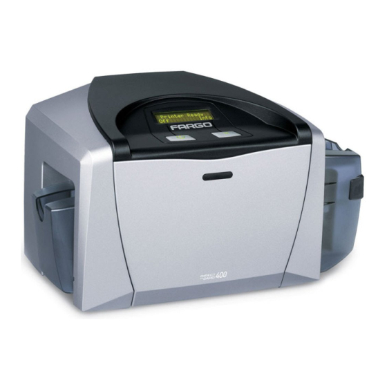
The Card Input Motor and Print Stepper Motor engage. The Card Feed Sensor detects leading edge of card and disengages the card input Motor. Continued on the next page Output Hopper Input Hopper Cartridge Bay DTC400e Card Printer User Guide (L001172 Rev. 1.1) 1-11... - Page 12 The Headlift Motor engages. The Print Headlift Sensor detects an open state. The Print Headlift Motor disengages. The Print Stepper Motor engages. The Print Ribbon Drive engages. Continued on the next page DTC400e Card Printer User Guide (L001172 Rev. 1.1) 1-12...
- Page 13 Repeat steps 9 through 22 for the appropriate number of color/overlay panels. The Card is ejected from the singled-sided Printer. The Card Feed Stepper engages to queue the card for the Flipper Table for the dual-sided Printer. All Stop. DTC400e Card Printer User Guide (L001172 Rev. 1.1) 1-13...
-
Page 14: Reviewing The Dtc400E Boot Up Sequence
If the Headlift Sensor is found to be open, the Headlift Motor will turn until a closed state is seen. If the Card Feed Sensor is found to be blocked, the Card Feed Stepper will engage to eject the card. DTC400e Card Printer User Guide (L001172 Rev. 1.1) 1-14... -
Page 15: Section 2: Specifications
European Community and has placed the CE mark on the Card Printer.) License Number: J99032510 The Card Printer is listed under UL IEC 60950-1 (2001) INFORMATION TECHNOLOGY EQUIPMENT. File Number: E145118 DTC400e Card Printer User Guide (L001172 Rev. 1.1) -
Page 16: Agency Listings
100 cards (30 mil) Hopper Capacity Colors Up to 16.7 million: Monochrome Dimensions See the Size and Weight information in this same table. Humidity 20-80% non-condensing Interface USB 2.0 Continued on the next page DTC400e Card Printer User Guide (L001172 Rev. 1.1) - Page 17 High or Low Coercivity. See the Using the Magnetic Encoding tab section. Memory 2MB RAM Monochrome The DTC400e shall render rewriteable card images using a monochrome Printing color pallet. Operating 65° to 80° F / 18° to 27° C Temperature Print Area...
- Page 18 Single-sided (size): 7.90"H x 13.62"W x 8.14"D / 200mmH x 346mmW x 207mmD • Dual-sided (weight): 12 lbs. / 5.45 kg • Dual-sided (size): 7.9"H x 18.28"W x 8.14"D / 200mmH x 465mmW x 207mmD DTC400e Card Printer User Guide (L001172 Rev. 1.1)
-
Page 19: Functional Specifications
The following describes how each of these technologies works: Function Description Dye- Dye-Sublimation is the print method the DTC400e uses to produce smooth, Sublimation continuous-tone images that look truly photographic. (Note: This process uses a dye-based Ribbon roll that is partitioned by a number of consecutive color panels.) -
Page 20: Printer Components: Front Cover To Usb Port
Automatically cleans cards for higher print quality. Cleaning Roller Card Input Load blank cards into this Hopper. Hopper Power Port Connect to the included power cord. USB Port Connect to a Windows PC with a USB cable. DTC400e Card Printer User Guide (L001172 Rev. 1.1) -
Page 21: Printer Components: Print Ribbons
Ribbon panels found on each Ribbon. This letter code is as follows: = Dye-Sublimation Yellow Panel = Dye-Sublimation Magenta Panel = Dye-Sublimation Cyan Panel = Resin Black Panel = Clear Protective Overlay Panel = Ultra Violet Fluorescing Panel DTC400e Card Printer User Guide (L001172 Rev. 1.1) -
Page 22: Printer Components: Resin-Only Print Ribbons
Resin-only print Ribbons consist of a continuous roll of a single resin color. No protective overlay panel (O) is provided since resin images do not require the protection of such an overlay. The following resin-only Ribbon types are available for use with both DTC400e: Type... -
Page 23: Printer Components: Dye-Sublimation Print Ribbons
(Note: To avoid this area when printing, use the options in the Overlay / Print Area tab to omit printing in this area or punch the slot after the card has printed.) DTC400e Card Printer User Guide (L001172 Rev. 1.1) -
Page 24: Printer Components: Dye-Sublimation/Resin Print Ribbons
The designation of colored Ribbon by the Panels of color in the order in which they are printed: Yellow (Y), Magenta (M), Cyan (C) Ultra Violet Fluorescing Panel (F) Black (K), Overlay (O), Black (K), DTC400e Card Printer User Guide (L001172 Rev. 1.1) 2-10... -
Page 25: Printer Components: Blank Cards
UltraCard stock has a PVC core and offers medium card durability. UltraCard III stock has a 40% polyester core and offers high durability. • Both types of UltraCards produce printed images with a glossy, photo- quality finish. DTC400e Card Printer User Guide (L001172 Rev. 1.1) 2-11... -
Page 26: Printer Module: Flipper Table Module Assembly (D900200)
See the Front and Back radio buttons in the Using the K Panel Resin tab (DTC400e) section. • See the DTC400e Card Printer User Guide for the replacement procedures for this Printer. DTC400e Card Printer User Guide (L001172 Rev. 1.1) 2-12... -
Page 27: Section 3: Setup And Installation Procedures
Fargo Electronics, Inc. Section 3: Setup and Installation Procedures The following guide will walk you through the installation of the DTC400e Card Printer Driver. • Time Requirement (software): This software installation process will require approximately 2 to 5 minutes (depending on the speed of your PC). -
Page 28: Unpacking And Inspection
US / EU Power Cable • Software Installation CD/User Guide • User Guide • Warranty Statement, Registration Card and Compliancy Document Reviewing the Printer (front view) Output Hopper Input Hopper Cartridge Bay DTC400e Card Printer User Guide (L001172 Rev. 1.1) -
Page 29: Reviewing The Printer (Front View; Cartridge Being Installed)
RESTRICTED USE ONLY Fargo Electronics, Inc. Reviewing the Printer (front view; Cartridge being installed) DTC400e Card Printer User Guide (L001172 Rev. 1.1) -
Page 30: Connecting The Printer Power
Plug the wall power cable into the AC power adapter. Plug the wall power cable into a standard 110VAC power outlet. Display A – Shows back of Printer with AC power cable (below). DTC400e Card Printer User Guide (L001172 Rev. 1.1) -
Page 31: Installing The Print Ribbon Cartridge
RESTRICTED USE ONLY Fargo Electronics, Inc. Installing the Print Ribbon Cartridge The Fargo DTC400e Card Printer uses a one-piece, disposable Ribbon Cartridge load system. Every full color Ribbon Cartridge contains a 250 “full color card count” Ribbon and a Card Cleaning Roller. - Page 32 Display A – Shows the Print Ribbon Cartridge before it is installed or inserted into the Printer. The Card Cleaning Roller (see arrow) is already inserted into the Print Ribbon Cartridge. DTC400e Card Printer User Guide (L001172 Rev. 1.1)
- Page 33 RESTRICTED USE ONLY Fargo Electronics, Inc. Installing the Print Ribbon Cartridge (continued) Display B – Shows direction that Cartridge is inserted in the Printer. DTC400e Card Printer User Guide (L001172 Rev. 1.1)
-
Page 34: Installing Blank Cards Into The Card Hopper
RESTRICTED USE ONLY Fargo Electronics, Inc. Installing Blank Cards into the Card Hopper The Fargo DTC400e Printer is capable of printing single load cards and multiple feed cards (batch mode). • To print using single feed, simply remove all cards from the Card Hopper, leave the Card Hopper door closed and place a card in the single Feed Card Slot (which can be used repeatedly). - Page 35 Installing Blank Cards into the Card Hopper (continued) Display B - Press the Card Hopper Load Lever down. Insert the cards. Here the Lever is still up. Here the Lever is pressed down. DTC400e Card Printer User Guide (L001172 Rev. 1.1)
- Page 36 RESTRICTED USE ONLY Fargo Electronics, Inc. Installing Blank Cards into the Card Hopper (continued) Here are the cards ready to insert. Here the Input Hopper Door is closed. DTC400e Card Printer User Guide (L001172 Rev. 1.1) 3-10...
-
Page 37: Lowering The Card Output Hopper
Lowering the Card Output Hopper Step Procedure The Fargo DTC400e comes with a Card Output Hopper (to hold cards after they have been printed). Pull the Output Hopper down until it snaps into place. DTC400e Card Printer User Guide (L001172 Rev. 1.1) -
Page 38: Installing The Flipper Table Module Assembly (D900200)
Fargo Electronics, Inc. Installing the Flipper Table Module Assembly (D900200) Step Description Caution: Turn off the Printer and unplug the power cord from the Printer. Remove the Rear Cover (D90066) to the Printer. DTC400e Card Printer User Guide (L001172 Rev. 1.1) 3-12... - Page 39 Fargo Electronics, Inc. Installing the Flipper Table Module Assembly (D900200) (continued) Step Description Remove the Card Output or Exit Door (D900092) and Left End Cap (D900064) to the Printer, as shown below. DTC400e Card Printer User Guide (L001172 Rev. 1.1) 3-13...
- Page 40 Use the Torx T-10 screwdriver to attach the one (1) front Base plate mount screws (F000170), as shown below. Attach the Flipper Table Module Cover, as shown below. Connect the USB and Power cables, as shown below. DTC400e Card Printer User Guide (L001172 Rev. 1.1) 3-14...
-
Page 41: Printer Driver Installation
Explorer to view the contents of the CD. Then, double-click on the Setup.exe file listed on the CD.) Click on the following buttons to install the appropriate Printer Driver and Online User’s Guide, as shown below: INSTALL button for the DTC400e Card Printer/Encoder DTC400e Card Printer User Guide (L001172 Rev. 1.1) 3-15... - Page 42 RESTRICTED USE ONLY Fargo Electronics, Inc. Installing the Printer Driver (continued) Step Procedure Click on the Next button to continue with the Setup program. DTC400e Card Printer User Guide (L001172 Rev. 1.1) 3-16...
- Page 43 RESTRICTED USE ONLY Fargo Electronics, Inc. Installing the Printer Driver (continued) Step Procedure Read the License Agreement. Select the I accept the license agreement option and click Next to continue. DTC400e Card Printer User Guide (L001172 Rev. 1.1) 3-17...
- Page 44 Next to continue with the installation. Select Network Connection (Ethernet) if the printer is equipped with an Ethernet port and enter the Printer’s IP address. Click Next to continue with the installation. DTC400e Card Printer User Guide (L001172 Rev. 1.1) 3-18...
- Page 45 RESTRICTED USE ONLY Fargo Electronics, Inc. Installing the Printer Driver (continued) Step Procedure Click Next to begin the installation. DTC400e Card Printer User Guide (L001172 Rev. 1.1) 3-19...
- Page 46 Installing the Printer Driver (continued) Step Procedure Wait while the DTC400e Card Printer is configuring your new software installation. This step only applies to local connection installation (USB). a. Connect the USB cable to the Printer. b. Turn ON the Printer at this time if it is not already ON.
- Page 47 RESTRICTED USE ONLY Fargo Electronics, Inc. Installing the Printer Driver (continued) Step Procedure Select the installed Ribbon Type. DTC400e Card Printer User Guide (L001172 Rev. 1.1) 3-21...
- Page 48 RESTRICTED USE ONLY Fargo Electronics, Inc. Installing the Printer Driver (continued) Step Procedure Click on the Finish button to complete the Setup. DTC400e Card Printer User Guide (L001172 Rev. 1.1) 3-22...
- Page 49 Installing the Printer Driver (continued) Step Procedure • Click the Exit button to exit the installer, as shown below. • Click on Install the Fargo Workbench. You have completed the installation DTC400e Card Printer User Guide (L001172 Rev. 1.1) 3-23...
-
Page 50: Printing A Test Print Image
From your computer’s startup menu, select Settings > Printers and Faxes (Windows XP, 2003) or > Printers (Windows 2000). b. Double click on the DTC400e Card Printer under the Printers window. c. Select Printing Preferences under the Printer drop-down menu. This will bring up the DTC400e Printing Preferences window. - Page 51 RESTRICTED USE ONLY Fargo Electronics, Inc. Printing a Test Print Image (continued) Step Procedure This completes the DTC400e Card Printer/Encoder Installation procedure. DTC400e Card Printer User Guide (L001172 Rev. 1.1) 3-25...
-
Page 52: Printer Transport
Step Procedure The Printer can be transported by gripping it under the back lid, as shown in the photo below. You have completed the setup and installation procedures in this section. DTC400e Card Printer User Guide (L001172 Rev. 1.1) 3-26... -
Page 53: Section 4: General Troubleshooting
• To prevent equipment or media damage, take jewelry off of fingers and hands, as well as thoroughly clean hands to remove oil and debris before working on the Printer. DTC400e Card Printer User Guide (L001172 Rev. 1.1) -
Page 54: Communications Errors
Verify the Flipper Table Module Assembly is functioning properly by printing out cards in a test run. d. If you are experiencing problems, see Resolving the No Flipper Table Module problem. DTC400e Card Printer User Guide (L001172 Rev. 1.1) - Page 55 Program Group). 1) Go to the File menu and select Page Setup. 2) Click on the Printer button and select the DTC400e Card Printer. 3) Click OK and reset all four margins to zero. (Note: The WordPad will automatically replace the values with its minimum margins.) 4) Open the program and type: “This is a Test.”...
-
Page 56: Print Process Errors
Printer Error State: Card is not being detected by the Card TOF Sensor 11 seconds after the initiation of a print job causing the Printer to produce an error • Driver Monitor Error Display: Unable to Feed Card DTC400e Card Printer User Guide (L001172 Rev. 1.1) - Page 57 Press the Card Hopper Load Lever down until the Card Tray locks into place. c. Using the Fargo Workbench send a test print to the Printer. d. Gently touch the Card Hopper Feed Roller to verify that it is turning e.
- Page 58 Ensure that the Card Hopper Feed Motor power cable is securely connected to the Card Hopper Feed Motor. d. Use the Fargo Workbench to send a test print to the Printer. If the Card Hopper Feed Motor is not moving, continue to Step 8.
-
Page 59: Resolving A Card Not Fed Error (Two (2) Or More Card Feed At The Same Time)
Printer Error State: Card is not being detected by card TOF Sensor 11 sec after the initiation of a print job causing the Printer to produce an error • Driver Monitor Error Display: Unable to Feed Card DTC400e Card Printer User Guide (L001172 Rev. 1.1) - Page 60 The blocked Sensor should read +4.99 vdc. • The open Sensor should read +1.5 vdc. c. If the Card Feed TOF Sensor does not read properly, replace the Sensor. Clean the Card Feed Roller. DTC400e Card Printer User Guide (L001172 Rev. 1.1)
-
Page 61: Resolving A Ribbon Rfid Error (Ribbon Rfid Antenna Is Corrupted)
Symptom: Printer RFID Sensor does not detect a recognizable signal from the Ribbon. • Printer Error State: The Ribbon tag information is corrupted or incorrect. • Driver Monitor Error Display: Ribbon RFID Error DTC400e Card Printer User Guide (L001172 Rev. 1.1) - Page 62 Replace the Print Ribbon Cartridge. b. Press on the Resume button. c. If the error continues, see Resolving the Ribbon RFID Error (Ribbon RFID Sensor is Corrupted) in this section. DTC400e Card Printer User Guide (L001172 Rev. 1.1) 4-10...
-
Page 63: Resolving A Ribbon Rfid Error (Ribbon Rfid Sensor Is Corrupted)
Driver Monitor Error Display: Ribbon RFID Error Replace the Print Ribbon RFID Sensor. a. Replace the Print Ribbon RFID Sensor. b. Press on the Resume button. c. If the error continues, replace the Printer Main Board. DTC400e Card Printer User Guide (L001172 Rev. 1.1) 4-11... -
Page 64: Resolving The Mag Verify Error
Review the following information. • Symptom: The Printer is unable to verify encoded data. • Printer Error State: The Printer is unable to verify encoded data. • Driver Monitor Error Display: Mag Verify DTC400e Card Printer User Guide (L001172 Rev. 1.1) 4-12... - Page 65 Module docking station. e. If the Magnetic Module is properly seated, replace the magnetic head (as needed). (Note: See the current DTC400e User Guide for related instructions in the Parts Replacement Section.) If data is being written to the Magnetic Stripe, the Magnetic Offset may need to be adjusted.
- Page 66 RESTRICTED USE ONLY Fargo Electronics, Inc. Resolving the Mag Verify Error (continued) DTC400e Card Printer User Guide (L001172 Rev. 1.1) 4-14...
-
Page 67: Resolving The No Mag Installed Error
Symptom: There is not a Magnetic Encoder installed. • Printer Error State: A print job with Magnetic encoding was sent with no Magnetic encoder installed in the Printer. • Driver Monitor Error Display: No Mag Installed DTC400e Card Printer User Guide (L001172 Rev. 1.1) 4-15... - Page 68 Printer is equipped with a Magnetic Encoder Module, ensure that it is seated securely into the Magnetic Module docking station. If the issue persists, replace the Magnetic Module. See the DTC400e service manual for replacement procedures.) If the Printer has no Magnetic Encoder Module, verify that the encoding data was sent in error, check the appropriate software user’s manual for encoding...
-
Page 69: Resolving A Ribbon Sensor Error (Ribbon Miscue)
• Symptom: The Printer rolls through Ribbon and errors out • Printer Error State: The Printer cannot find the next panel on the Ribbon. • Driver Monitor Error Display: Ribbon Sensor DTC400e Card Printer User Guide (L001172 Rev. 1.1) 4-17... - Page 70 Use the Driver Calibration tab to calibrate the Ribbon Sensor. Cover the front of the printer to block the light while calibrating this sensor. • If the issue persists, continue to Step 8. Replace the Ribbon Sensor. DTC400e Card Printer User Guide (L001172 Rev. 1.1) 4-18...
-
Page 71: Resolving A Ribbon Break Jam Error
Symptom: The Print Ribbon has become jammed or has broken in the Printer • Printer Error State: The Ribbon Supply Encoder Sensor has unexpectedly stop receiving information from the Ribbon Encoder • Driver Monitor Error Display: Ribbon BreakJam DTC400e Card Printer User Guide (L001172 Rev. 1.1) 4-19... - Page 72 Repair the Ribbon and wind up the take-up roll 4 color panels past the damaged area. a. Press on the Resume button. b. If the issue persists, continue to Step 5. Use the Fargo Workbench to cycle the Printhead to ensure proper printhead operation. • If the Printhead does not cycle properly, see...
-
Page 73: Resolving A Ribbon Out Error
• Printer Error State: The Ribbon Sensor has detected the End Of Ribbon mark • Driver Monitor Error Display: Ribbon Out Replace the Ribbon Cartridge a. Press on the Resume button. DTC400e Card Printer User Guide (L001172 Rev. 1.1) 4-21... -
Page 74: Resolving A No Ribbon Installed Error
Symptom: Printer errors out as soon as it receives data from PC • Printer Error State: The Printer RFID Sensor is not receiving a signal from the Ribbon • Driver Monitor Error Display: No Ribbon Installed DTC400e Card Printer User Guide (L001172 Rev. 1.1) 4-22... - Page 75 If the connections are loose, reattach them. • Press on the Resume button. • If the connections are good or if the issue persists, continue to Step 4. Replace the Ribbon RFID Sensor. DTC400e Card Printer User Guide (L001172 Rev. 1.1) 4-23...
-
Page 76: Resolving A Invalid Ribbon Error
Symptom: Printer errors out as soon as it receives data from the PC • Printer Error State: The Ribbon installed does not match the Printer model. • Driver Monitor Error Display: Invalid Ribbon DTC400e Card Printer User Guide (L001172 Rev. 1.1) 4-24... - Page 77 If the connections are loose, reattach • Press on the Resume button.. • If the connections are good or if the issue persists, continue to Step 5. Replace the Ribbon RFID Sensor. DTC400e Card Printer User Guide (L001172 Rev. 1.1) 4-25...
-
Page 78: Resolving A Wrong Ribbon Error
Symptom: Printer errors out as soon as it receives data from the PC • Printer Error State: The Ribbon installed does not match the Printer Driver information • Driver Monitor Error Display: Wrong Ribbon DTC400e Card Printer User Guide (L001172 Rev. 1.1) 4-26... - Page 79 Verify the Driver settings are correct. a. Open the Printer Control Panel from the Computer. • If using Windows 2000/XP, right click on the DTC400e Card Printer and select Printing Preferences. b. Click on the Device Option tab. c. Click on the auto select button.
-
Page 80: Resolving A Card Jam Error
Printer. Step Procedure Review the following information. • Symptom: Card is jammed. • Printer Error State: Card TOF Sensor is detecting no card motion • Driver Monitor Error Display: Card Jam DTC400e Card Printer User Guide (L001172 Rev. 1.1) 4-28... - Page 81 If unblocked, the Sensor should read 0.15 to 0.18 VDC. d. If the voltages do not read correctly, replace the Sensor. (Note: See the current DTC400e User Guide for related instructions in the Parts Replacement Section.) DTC400e Card Printer User Guide (L001172 Rev. 1.1)
-
Page 82: Resolving A Headlift Motor Or Sensor Error
Symptom: The Printhead continuously cycles or does not cycle at all • Printer Error State: Headlift Sensor is not detecting movement from the Headlift Cam • Driver Monitor Error Display: General Error DTC400e Card Printer User Guide (L001172 Rev. 1.1) 4-30... - Page 83 Replacement Section.) d. If the Motor does turn, continue to Step 7. Replace the Headlift Motor. (Note: See the current DTC400e User Guide for related instructions in the Parts Replacement Section.) a. If the Motor does turn, continue to Step 8.
-
Page 84: Resolving The Cover Open Error Message
Section.) b. If the Sensor still does not work, continue to Step 4. Replace the Main Board. (Note: See the current DTC400e User Guide for related instructions in the Parts Replacement Section.) DTC400e Card Printer User Guide (L001172 Rev. 1.1) -
Page 85: Resolving The Blank Output Issues
Visually inspect the set of panels that were last used by the Printer. d. If an image is noticeable on the used Ribbon, continue to Step 4. e. If an image is not noticeable on the used Ribbon, continue to Step 5. DTC400e Card Printer User Guide (L001172 Rev. 1.1) 4-33... - Page 86 Reset the Printer to clear any Error Messages by removing the power and reapplying it. b. Open the Printer Control Panel from the Computer. • If using Windows 2000/XP, right click on the DTC400e Card Printer and select Printing Preferences. c. Click on the Calibrate tab. d. Click on the Settings button.
- Page 87 If less than 22 volts is read on any of the pins, replace the Printhead. • If still having issue with blank cards, replace the Main Board. (See the current DTC400e User Guide for instructions on replacing the Main Board in the Parts Replacement Section.) DTC400e Card Printer User Guide (L001172 Rev. 1.1)
-
Page 88: Resolving The Remove Ribbon Message (Rewriteable Job)
Printer and there is a Ribbon in the Printer. • Printer Error State: The error message will instruct the user to remove the ribbon from the printer. • Driver Monitor Error Display: None DTC400e Card Printer User Guide (L001172 Rev. 1.1) 4-36... -
Page 89: Flipper Table Module Assembly Problems
Symptom: The Flipper Table Module Assembly is not functioning. • Printer Error State: The Printer is unable to communicate with the Flipper Module. • Driver Monitor Error Display: No Flipper Module DTC400e Card Printer User Guide (L001172 Rev. 1.1) 4-37... -
Page 90: Resolving The Flipper Jam Error
Symptom: The Flipper Table Module is jamming. • Printer Error State: The Flipper Table has jammed while either aligning itself or flipping a card. • Driver Monitor Error Display: Flipper Jam DTC400e Card Printer User Guide (L001172 Rev. 1.1) 4-38... - Page 91 Close the Printer’s Flipper Table Module. d. Press the Resume button on the Printer’s Top Cover to continue printing. e. To cancel the printing, press the Cancel Print button from the Driver’s display dialog. DTC400e Card Printer User Guide (L001172 Rev. 1.1) 4-39...
-
Page 92: Diagnosing Image Problems
Check the card stock for scratches. Replace the cards (as needed). Examine the Printhead for visible damage. Clean the Printhead. See the procedure Cleaning the Printhead Replace the Printhead if the problem persists. DTC400e Card Printer User Guide (L001172 Rev. 1.1) 4-40... -
Page 93: Resolving The Card Surface Debris Problems
Clean the inside of the Printer. See Cleaning the Printer’s Interior Clean the Cleaning Roller. See Cleaning the Platen and the Card Feed Rollers. DTC400e Card Printer User Guide (L001172 Rev. 1.1) 4-41... -
Page 94: Resolving The Incorrect Image Darkness Problems
Run a self-test to ensure that the issue is not with the Driver settings. Adjust the Dye-Sub Intensity setting within the Image Color tab of the Printer Driver. See Using the Image Color tab (DTC400e) procedure. DTC400e Card Printer User Guide (L001172 Rev. 1.1) 4-42... - Page 95 RESTRICTED USE ONLY Fargo Electronics, Inc. Resolving the Incorrect Image Darkness problems (continued) Step Procedure Correct the Image Darkness. See the Using the Image Darkness Option procedure. DTC400e Card Printer User Guide (L001172 Rev. 1.1) 4-43...
-
Page 96: Resolving Ribbon Wrinkle Problems
Confirm that the Printer is using the most current Driver via: http://www.fargo.com Reduce the Dye-Sub Intensity setting within the Image Color tab of the Printer Driver. See the Using the Image Color tab (DTC400e). DTC400e Card Printer User Guide (L001172 Rev. 1.1) 4-44... - Page 97 RESTRICTED USE ONLY Fargo Electronics, Inc. Resolving Ribbon Wrinkle problems (continued) Step Procedure Reduce the Image Darkness. See the Using the Image Darkness Option procedure. DTC400e Card Printer User Guide (L001172 Rev. 1.1) 4-45...
-
Page 98: Resolving The Excessive Resin Printing Problems
Printer Error State: None • Driver Monitor Error Display: None Reduce the Resin Heat setting within the Image Color tab of the Printer Driver. See the Using the Image Color tab (DTC400e). DTC400e Card Printer User Guide (L001172 Rev. 1.1) 4-46... - Page 99 RESTRICTED USE ONLY Fargo Electronics, Inc. Resolving the Excessive Resin printing problems (continued) Step Procedure Reduce the Image Darkness. See the Using the Image Darkness Option procedure. DTC400e Card Printer User Guide (L001172 Rev. 1.1) 4-47...
-
Page 100: Resolving The Incomplete Resin Printing Problems
Increase the Resin Heat setting within the Image Color tab of the Printer Driver. See the Using the Image Color tab (DTC400e). Increase the Image Darkness. See the Using the Image Darkness Option procedure. DTC400e Card Printer User Guide (L001172 Rev. 1.1) 4-48... -
Page 101: Resolving The Image Placement Problems
Symptom: Printing is cut off or is not centered on the card or a white border appears. • Printer Error State: None • Driver Monitor Error Display: None Continued on the next page DTC400e Card Printer User Guide (L001172 Rev. 1.1) 4-49... - Page 102 Open the Printer Control Panel from the Computer. • If using Windows 2000/XP, right click on the DTC400e Card Printer and select Printing Preferences. b. Click on the Calibrate tab. c. Adjust the Vertical and/or Horizontal Image Position settings based on where the white border is on the card.
- Page 103 If the white border is on the trailing edge of the card, adjust the Horizontal value by -2. a. Click on OK. b. Run a self-test. c. If the white border is diminished, continue the adjustment until it is gone. Graphic A DTC400e Card Printer User Guide (L001172 Rev. 1.1) 4-51...
- Page 104 If the white border is on the bottom edge of the card, adjust the Vertical value by -2. b. Click on OK. c. Run a self-test. d. If the white border is diminished, continue the adjustment until it is gone. DTC400e Card Printer User Guide (L001172 Rev. 1.1) 4-52...
-
Page 105: Resolving The Poor Image Quality Problems
If a small or low-resolution image is stretched or blown up, a pixilated or grainy effect will occur when printing, as shown below (rightside). DTC400e Card Printer User Guide (L001172 Rev. 1.1) 4-53... -
Page 106: Running The Self Test
The overlay pass is not printed during the Self-test. (See Display A below) • Premium Resin Ribbon Cartridge installed: The Printer will print a single color gray scale on the front of the card. See Display B below) DTC400e Card Printer User Guide (L001172 Rev. 1.1) 4-54... -
Page 107: Running The Standard Self Test Print
RESTRICTED USE ONLY Fargo Electronics, Inc. Running the Standard Self Test Print Display A: Full Color Test Print DTC400e Card Printer User Guide (L001172 Rev. 1.1) 4-55... -
Page 108: Running The Magnetic Self Test (Hico Only)
Press and hold the Pause/Resume button. While holding down the Pause/Resume button, plug the power cable back into the Printer. The Printer will Encode magnetic information on all 3 magnetic tracks DTC400e Card Printer User Guide (L001172 Rev. 1.1) 4-56... -
Page 109: Section 5: Ethernet Option
Printer Management: The Printer Driver provides bi-directional status information so you can monitor and manage the Printer just as you would any other networked Printer. • Compatibility: The Fargo Ethernet option provides compatibility with TCP/IP and 802.3 Ethernet protocols with an IEEE 802.3 10/100Base-T Ethernet female RJ45 connector. •... -
Page 110: Functional Specification - Ethernet Option
Troubleshooting Provides a Ping client for network troubleshooting. IP Tracer Provides a utility (IP Tracer) used to find Fargo Printers with Ethernet connection on a local network. (Note: This utility is included on the CD-ROM and online at www.fargo.com.) DTC400e Card Printer User Guide (L001172 Rev. 1.1) -
Page 111: Network Services - Overview
• All clients are able to send print jobs to the Printer and monitor Printer jobs and errors with the standard Windows printing system using the Fargo Printer Driver installed on their local PC. In this way, the User knows whether or not a print job has been successful. Also, the User knows what problems have been encountered while processing the print job. -
Page 112: Network Management Interface
Telnet session on the PC. • All commands entered will be sent to the Telnet client in the Printer. Enter help or ? to get an on-window list of supported Telnet commands. DTC400e Card Printer User Guide (L001172 Rev. 1.1) -
Page 113: Reviewing The Telnet Command Table
Display help for Telnet commands. help Reset the Ethernet interface for reset reset the Printer/Encoder. Send a ping command to another ping <IPADDR> ping IP address as a test of the Ethernet interface. DTC400e Card Printer User Guide (L001172 Rev. 1.1) - Page 114 Display information about the list default net default network settings of the Ethernet interface. user Display information about the list user defined User names and their type (root or guest privileges). DTC400e Card Printer User Guide (L001172 Rev. 1.1)
- Page 115 Display information list printer about the Printer (i.e., model number, Firmware version and serial number). printer Display information list printer sm about the secure mark settings of the Printer. DTC400e Card Printer User Guide (L001172 Rev. 1.1)
- Page 116 Specify the IP address set syslog <LOG_NAME> udp of the UPD system <IPADDRESS> logging program. from Restore system log set syslog from default|current path settings from the default or current settings. DTC400e Card Printer User Guide (L001172 Rev. 1.1)
- Page 117 Specify a User as root set user type <NAME> or guest. root|guest Only root Users have administrative rights to change network interface settings. from Restore User setting set user from default|stored from default or stored settings. DTC400e Card Printer User Guide (L001172 Rev. 1.1)
- Page 118 10 or 100 mHz. from Set the Ethernet mode store ifc from default|current settings from the default or current settings. DTC400e Card Printer User Guide (L001172 Rev. 1.1) 5-10...
-
Page 119: Ethernet Web Pages - Standard Procedures
Ethernet Web Pages – Standard Procedures Reviewing Web page security You can use the web pages from your Fargo Ethernet-connected Printer to view several attributes about the Printer. Users must have administrative rights, and they must enter the correct password to alter settings of the Printer. See the Reviewing the Web Page Server section. -
Page 120: Logging In
Press Enter or click on the OK button. If the name and password is not accepted, another login prompt will appear on screen. Repeat this procedure with the correct User name and password. DTC400e Card Printer User Guide (L001172 Rev. 1.1) 5-12... -
Page 121: Accessing The Home Page
Press Enter or click on GO. View the Home page. The Home Page displays general information about the Printer. See the next page. Display – See Procedural Steps 2 and 3 (above) DTC400e Card Printer User Guide (L001172 Rev. 1.1) 5-13... -
Page 122: Reviewing The Home Page
RESTRICTED USE ONLY Fargo Electronics, Inc. Reviewing the Home Page This section displays the DTC400e Home Page. The window title bar will vary according to the serial number assigned to your Printer. DTC400e Card Printer User Guide (L001172 Rev. 1.1) -
Page 123: Reviewing The Home Page Categories And Fields (Table)
User assigns to the Printer. Set by Firmware Version Displays the current Firmware version of the Firmware (Print Server) Print Server. Firmware Version Displays the current Firmware version of the (Printer) Printer. DTC400e Card Printer User Guide (L001172 Rev. 1.1) 5-15... -
Page 124: Configuring The Network Settings
Accessing the Network Settings page The Network page displays the current network settings and allows the User to change the settings. Step Procedure Select the Network link from any web page of the Printer. DTC400e Card Printer User Guide (L001172 Rev. 1.1) 5-16... -
Page 125: Reviewing The Interface
These are also labeled as Dynamic if they were provided by DHCP or Static if they came from the Stored Settings. • The current settings will be Dynamic only if Obtain an IP address automatically was selected when the Printer was restarted last. DTC400e Card Printer User Guide (L001172 Rev. 1.1) 5-17... -
Page 126: Switching To The Automatic Ip Address Mode
Log in as a root User if you are so prompted. (Note: Any change of setting will only be accepted after you have successfully logged in.) Reboot the Printer to affect this change. See the procedures in Using the Reboot pages. DTC400e Card Printer User Guide (L001172 Rev. 1.1) 5-18... -
Page 127: Changing To The Static Ip Address Mode
Select the Submit button to save these changes to stored settings in the memory of the Printer. (Note: These settings will not be lost if the power is removed from the Printer.) DTC400e Card Printer User Guide (L001172 Rev. 1.1) 5-19... - Page 128 Log in as a root User if you are so prompted. (Note: Any change of setting will only be accepted after you have successfully logged in.) Reboot the Printer to effect this change. See the Reviewing Web page security procedure. DTC400e Card Printer User Guide (L001172 Rev. 1.1) 5-20...
-
Page 129: Entering The Tcp Window Size
Login as a root User if you are so prompted. (Note: Any change of setting will only be accepted after you have successfully logged in.) Reboot the Printer to effect this change. See the Reviewing Web page security procedure. DTC400e Card Printer User Guide (L001172 Rev. 1.1) 5-21... - Page 130 RESTRICTED USE ONLY Fargo Electronics, Inc. DTC400e Card Printer User Guide (L001172 Rev. 1.1) 5-22...
-
Page 131: Using The Clear Changes Button
Using the Clear Changes button Step Procedure Click on the Clear Changes button to delete the information in the textboxes in Stored Settings area. See the lower left corner of this display. DTC400e Card Printer User Guide (L001172 Rev. 1.1) 5-23... -
Page 132: Using The Print Path Page
View the active configuration of the printer in the Current Settings area on this page. New port numbers may be entered into the Stored Settings area in the text boxes provided on this page. DTC400e Card Printer User Guide (L001172 Rev. 1.1) 5-24... - Page 133 Printer. (Note: These settings will not be lost if the power is removed from the Printer.) Select the Clear Changes button to delete these changes from this page. DTC400e Card Printer User Guide (L001172 Rev. 1.1) 5-25...
-
Page 134: Using The Ribbon Information Page
Select the Status link from any web page of the Printer. Select the Ribbon page link. View currently-installed Ribbon information pertaining to the following: • Part Number • SecureMark Part Number • Percent Remaining • Ribbon Type DTC400e Card Printer User Guide (L001172 Rev. 1.1) 5-26... -
Page 135: Using The Tcp/Ip Page
Select the TCP/IP page link. View information on all current network connections in the TCP connections area. Review information on the network DHCP status in the DHCP Information area. Continued on the next page DTC400e Card Printer User Guide (L001172 Rev. 1.1) 5-27... -
Page 136: Using The Tcp/Ip Status Web Page
RESTRICTED USE ONLY Fargo Electronics, Inc. Using the TCP/IP Status Web Page See the Using the TCP/IP page procedure on the previous page. DTC400e Card Printer User Guide (L001172 Rev. 1.1) 5-28... -
Page 137: Using The Printer Page
Printer. (Note: The current job that is being received by the interface is displayed as the active job.) Cancel a specific print job by selecting the appropriate Cancel button, which appears when a print job is queued. DTC400e Card Printer User Guide (L001172 Rev. 1.1) 5-29... - Page 138 RESTRICTED USE ONLY Fargo Electronics, Inc. Reviewing the Printer page (continued) See the previous page for descriptions of the fields. DTC400e Card Printer User Guide (L001172 Rev. 1.1) 5-30...
-
Page 139: Using The System Log Page
Using the System Log page The System Log page displays the current system log settings and allows the User to change the settings. (Note: These settings configure how system logging occurs. There are two logs.) DTC400e Card Printer User Guide (L001172 Rev. 1.1) 5-31... -
Page 140: Changing The Log Name
By default the names are log1 and log2. However, you can rename them from this page. (Note: This also updates the link to the corresponding web page.) Step Procedure Select the System Log link. DTC400e Card Printer User Guide (L001172 Rev. 1.1) 5-32... - Page 141 Click on the Submit button to save this change. Log in as a root User if you are so prompted. (Note: Any change of setting will only be accepted after you have successfully logged in.) DTC400e Card Printer User Guide (L001172 Rev. 1.1) 5-33...
-
Page 142: Selecting The Log Type
Printer Error. Select the Submit button. Login as a root User if you are so prompted. (Note: Any change of setting will only be accepted after you have successfully logged in.) DTC400e Card Printer User Guide (L001172 Rev. 1.1) 5-34... -
Page 143: Selecting The Log Destination
Select the None radio button when no log is required. (Note: This is the default.) Select Submit. Login as a root User if you are so prompted. (Note: Any change of setting will only be accepted after you have successfully logged in.) DTC400e Card Printer User Guide (L001172 Rev. 1.1) 5-35... -
Page 144: Setting Up Email Event Logging
Enter a valid e-mail address in the associated textbox. Select Submit. Log in as a root User if you are so prompted. (Note: Any change of setting will only be accepted after you have successfully logged in.) DTC400e Card Printer User Guide (L001172 Rev. 1.1) 5-36... -
Page 145: Specifying Udp Event Logging
Select the link for the log name you want to view or configure (the default choices are log1 or log2). Select the UDP Syslog radio button. Enter a valid IP address or domain name. Continued on the next page DTC400e Card Printer User Guide (L001172 Rev. 1.1) 5-37... - Page 146 Specifying UDP Event logging Step Procedure Select Submit. Log in as a root User if you are so prompted. (Note: Any change of setting will only be accepted after you have successfully logged in.) DTC400e Card Printer User Guide (L001172 Rev. 1.1) 5-38...
-
Page 147: Specifying Tcp Event Logging
Procedure Select the System Log link. Select the link for the log name you want to view or configure (the default choices are log1 or log2). Continued on the next page DTC400e Card Printer User Guide (L001172 Rev. 1.1) 5-39... - Page 148 Log Messages: All system log messages would then be displayed in that Telnet session window. (Note: This is a one way connection for logging only. Any input to the Printer on this connection is ignored.) DTC400e Card Printer User Guide (L001172 Rev. 1.1) 5-40...
-
Page 149: Using The Administration Pages
Select the link for the System web page. To change an attribute, type the new entry in one of these boxes: • Label textbox • Location textbox • Contact textbox Continued on the next page DTC400e Card Printer User Guide (L001172 Rev. 1.1) 5-41... - Page 150 Step Procedure Select the Submit button. Log in as a root User if you are so prompted. Any change of setting will only be accepted after you have successfully logged in. DTC400e Card Printer User Guide (L001172 Rev. 1.1) 5-42...
-
Page 151: Changing The Root Password
Re-enter the new password in the Root Password Confirm textbox or leave it blank if you want to remove the old password. Continued on the next page DTC400e Card Printer User Guide (L001172 Rev. 1.1) 5-43... - Page 152 Select the Submit button. Log in as a root User (using the password) if you are so prompted. (Note: Any change of setting will only be accepted after you have successfully logged in.) DTC400e Card Printer User Guide (L001172 Rev. 1.1) 5-44...
-
Page 153: Upgrading The Print Server
Log in as a root User (using the password) if you are so prompted. (Note: Any change of setting will only be accepted after you have successfully logged in.) Select the Upgrade link. Select the Browse button. Navigate to and select the appropriate file to upload. DTC400e Card Printer User Guide (L001172 Rev. 1.1) 5-45... - Page 154 RESTRICTED USE ONLY Fargo Electronics, Inc. Upgrading the DTC400e Print Server (continued) Step Procedure Select the Upgrade button to start the Firmware upload. Select Reboot when requested. DTC400e Card Printer User Guide (L001172 Rev. 1.1) 5-46...
-
Page 155: Using The Reboot Pages
RESTRICTED USE ONLY Fargo Electronics, Inc. Using the Reboot pages Rebooting the DTC400e restarts only the Ethernet Print Server. Rebooting the Ethernet Server The Reboot page allows the User to restart the Ethernet Print Server. Step Procedure Select the Administration link. - Page 156 RESTRICTED USE ONLY Fargo Electronics, Inc. Rebooting the Ethernet Server (continued) Step Procedure Click Yes when prompted. Wait for the Printer to reboot and display the home page. DTC400e Card Printer User Guide (L001172 Rev. 1.1) 5-48...
-
Page 157: Resetting To Default Settings
Any change of setting will only be accepted after you have successfully logged in.) Select the Reboot link. Select the Default button. Click the Yes button when prompted. Wait for the Printer to reboot and display the home page. DTC400e Card Printer User Guide (L001172 Rev. 1.1) 5-49... -
Page 158: Using The Help Page
Open this web page at the appropriate location by clicking on the Help book icon at the top of each page. See below. Review the web interface for the Ethernet-enabled Printer. DTC400e Card Printer User Guide (L001172 Rev. 1.1) 5-50... -
Page 159: Additional Procedures
The Network link is present. The Network link is not present. Blinking, off 1/3 second The Network link is present and transmitting. It flashes off for one-third (1/3) second each time a packet is transmitted. DTC400e Card Printer User Guide (L001172 Rev. 1.1) 5-51... -
Page 160: Reviewing The Dip Switches
RESTRICTED USE ONLY Fargo Electronics, Inc. Reviewing the Dip Switches For the DTC400e, ON means a Dipswitch is down and OFF means a Dipswitch is up. Dipswitch Comments Allows Normal operation. Forces Factory default settings. With the dip switches in this configuration, the unit will start up. All settings stored in permanent memory will be erased except for the Ethernet address and key value. -
Page 161: Upgrading The Main Firmware With The Fargo Workbench Printer Utility
The Main Printer Firmware upgrades are done with the same procedure as the USB- connected Printer. The PC doing the upgrade must have a Driver installed for the Fargo Printer to be upgraded. (Note: Alternatively, a DTC400e User can upgrade the DTC400e Main Printer Firmware by using the DTC400e Upgrade web page.) - Page 162 Select the New Firmware File by clicking Browse and selecting the Firmware file from the appropriate folder. Begin the upgrade by clicking Upgrade, as shown below. Refer to the Fargo Workbench Printer Utility User Guide at this time. DTC400e Card Printer User Guide (L001172 Rev. 1.1) 5-54...
-
Page 163: Restoring The Factory Settings For Ethernet
After 30 seconds, remove power, restore both switches to their normal position (which is OFF) and then restore power. Restoring the Default Settings The DTC400e has switches on the back which will restore the factory default settings to the Printer. •... -
Page 164: Accessing The Ip Address Of Your Printer
Scroll through the informational messages on the LCD by selecting the INFO button (the button on the right of the front panel). View the IP address displayed as a dotted quad number. Example: 168.192.1.1 DTC400e Card Printer User Guide (L001172 Rev. 1.1) 5-56... -
Page 165: Ethernet Printer Troubleshooting Procedures
Verify that the port configuration of the PC Printer Driver is set to communicate to the Printer over the correct IP address. Frequently-asked Questions. Follow the Printing a test page procedure. DTC400e Card Printer User Guide (L001172 Rev. 1.1) 5-57... -
Page 166: Verifying The Printer Connection
If the IP address is not valid, go to step 2 (below). If your network is using DHCP, then: • Use Fargo IP-Tracer to verify that the Printer has not been configured to use a static address. (Note: This guideline applies unless you have a known, unused static IP address assigned to this Printer.) -
Page 167: Verifying That Your Pc Can Access The Printer Using The Ping Command
See Display B below. Display A - Example of sending a ping to the Printer with a successful response Display B - Example of ping timeout to an invalid IP address DTC400e Card Printer User Guide (L001172 Rev. 1.1) 5-59... -
Page 168: Printing A Test Page
There may be an error at the Printer. • There may be a job in the Windows print queue which has stalled. • The Printer may be paused or set to operate offline in the Windows print queue. DTC400e Card Printer User Guide (L001172 Rev. 1.1) 5-60... -
Page 169: Reviewing Frequently-Asked Questions
If you do not know the IP address or the Printer does not work with a usable IP address, then the MAC Address can be found using the tool Fargo IP-Tracer. (Note: This can be installed and used to locate all the Fargo-compatible Printers on your network.) - Page 170 5. Enter the IP address of the Printer. Click Next. 6. Enter a name for the port. Click Next. 7. Click Finish. 8. Select Fargo for the Manufacturer and select the DTC400e for the Printer. Click Next. 9. Enter a name for the Printer instance. Click Next.
- Page 171 Ethernet-enabled Printer? installed for the Fargo Printer to be upgraded. Follow this procedure. 1. Run the Fargo Diagnostic Utility from the start menu: Go to the Start -> Programs -> Fargo -> Fargo Diagnostic Utility. 2. Select the Fargo Printer to upgrade from the drop- down box.
- Page 172 PC, server or network device. Use those settings to configure your Printer with static network settings. (Caution: Do not do this unless you know that these settings will always be available.) DTC400e Card Printer User Guide (L001172 Rev. 1.1) 5-64...
- Page 173 You can choose to configure the Printer, using a static IP address and network settings. (Note: This can be entered using the Network web page of the Printer or the Fargo IP Tracer program.) Configuring the Network Settings.
- Page 174 Accessing the Home page. Printer? You can use Fargo IP-Tracer which allows you to find Fargo-compatible Printers and specify their addresses. (Note: You can save static addresses. However, they are not used until you reconfigure the Printer to use those static addresses and reboot the Printer.)
-
Page 175: Glossary Of Terms
This is the address of the server that provides the translation from a Address descriptive name to an IP address. DNS Domain This is the suffix to be added to the domain name make a complete Suffix name. DTC400e Card Printer User Guide (L001172 Rev. 1.1) 5-67... - Page 176 A common utility or command that sends a message to network devices asking for a return message. (Note: This is used to diagnose if the device is on the network or to troubleshoot the connection.) DTC400e Card Printer User Guide (L001172 Rev. 1.1) 5-68...
-
Page 177: Section 6: Printer Adjustments
• To prevent equipment or media damage, take jewelry off of fingers and hands, as well as thoroughly clean hands to remove oil and debris before working on the Printer. DTC400e Card Printer User Guide (L001172 Rev. 1.1) -
Page 178: Dtc400E Print Driver Options
(Note No.2: The Card Size indicates that the Printer accepts standard, credit card size CR-80 (ISO ID-1) cards. The dimensions of the total print area for this card size appear in the Print Width: and Print Length: areas, as shown below.) DTC400e Card Printer User Guide (L001172 Rev. 1.1) -
Page 179: Adjusting The Orientation Option
Select Portrait to cause the card to print in a vertical orientation. Select Landscape to cause the card to print in a horizontal orientation. (Note: An icon illustrating a printed card helps represent the difference between the two.) DTC400e Card Printer User Guide (L001172 Rev. 1.1) -
Page 180: Selecting The Number Of Copies
RESTRICTED USE ONLY Fargo Electronics, Inc. Selecting the number of copies Step Description Select the number of copies by clicking on the UP or DOWN arrows, as shown below. DTC400e Card Printer User Guide (L001172 Rev. 1.1) -
Page 181: Using The Diagnostics Button Under The Card Tab
RESTRICTED USE ONLY Fargo Electronics, Inc. Using the Diagnostics button under the Card tab Step Description Click Diagnostics to bring up the Fargo Workbench window. DTC400e Card Printer User Guide (L001172 Rev. 1.1) -
Page 182: Using The Clean Printer Option
Remove all cards from the Card Hopper and close the Hopper door. Open the Front Cover and remove the Ribbon Cartridge. Remove the paper backing from both sides of the Cleaning Card. Place the Cleaning card into the Single Feed Slot. DTC400e Card Printer User Guide (L001172 Rev. 1.1) - Page 183 Using the Clean Printer Option (continued) Step Description Click Clean. (Note: The Printer will begin to feed the cleaning card through the card path.) Reinsert the print Ribbon and cards after the cleaning procedure has completed. DTC400e Card Printer User Guide (L001172 Rev. 1.1)
-
Page 184: Using The Test Print Button
Ensure that the computer is effectively communicating with the Printer and that the Printer is functioning properly. • Ensure that the YMCKOK Ribbon is installed in order for a DTC400e Card Printer with a Flipper Table Module to print a dual-sided image. DTC400e Card Printer User Guide (L001172 Rev. 1.1) -
Page 185: Using The About Button
RESTRICTED USE ONLY Fargo Electronics, Inc. Using the About button Step Description Click About to open a dialog box containing the copyright and version, date code information about this Printer Driver software. DTC400e Card Printer User Guide (L001172 Rev. 1.1) -
Page 186: Using The Device Options Tab
RESTRICTED USE ONLY Fargo Electronics, Inc. Using the Device Options tab Reviewing the Device Options tab The DTC400e window with the Device Options tab is displayed below. DTC400e Card Printer User Guide (L001172 Rev. 1.1) 6-10... -
Page 187: Adjusting The Ribbon Type Option
• K – Standard Resin • K – Premium Resin • Colored Resin • Metallic Resin • KO – Premium Resin/Overlay • BO – Dye Sub Black/Overlay • NONE – Re-Writable DTC400e Card Printer User Guide (L001172 Rev. 1.1) 6-11... -
Page 188: Selecting The None- Re-Writable Ribbon Type
This will speed up the process. The full card is erased and printed; there is no option to select specific areas to erase.) • To erase many cards, use the Fargo Workbench Re-Writable Card Eraser option. (Note: This option does not print only erase.) The Write Only checkbox is displayed when the NONE Re-Writeable Ribbon type is chosen. - Page 189 RESTRICTED USE ONLY Fargo Electronics, Inc. Selecting the NONE- Re-Writable Ribbon Type (continued) When the Re-Writeable Ribbon Type is selected, the DTC400e driver will show only relevant options. Step Description The following options are removed from the Device Options tab when the Re- Writeable Ribbon Type is selected.
-
Page 190: Using The Workbench (To Erase The Card)
RESTRICTED USE ONLY Fargo Electronics, Inc. Using the Workbench (to erase the card) Step Description Open the Diagnostic Tool box. DTC400e Card Printer User Guide (L001172 Rev. 1.1) 6-14... - Page 191 RESTRICTED USE ONLY Fargo Electronics, Inc. Using the Workbench (to erase the card) (continued) Step Description Select the Re-Writable Card Eraser option DTC400e Card Printer User Guide (L001172 Rev. 1.1) 6-15...
- Page 192 Step Description Select the number of cards to be erased. Click on the Erase button. (Note: This will erase the full card. The card may be stored or printed on again.) DTC400e Card Printer User Guide (L001172 Rev. 1.1) 6-16...
-
Page 193: Selecting The Auto Ribbon Select Option
Ribbon installed in the Printer. (Note: The Printer Driver will change the Ribbon type to the correct setting or validate. It will also display a dialog that it has changed the current setting or that the current Ribbon type is correct.) DTC400e Card Printer User Guide (L001172 Rev. 1.1) 6-17... - Page 194 From your computer’s startup menu, select Settings > Printers and Faxes (Windows XP) or Settings > Printers (Windows 2000). b. Double click on the DTC400e Card Printer under the Printers window. c. Select Properties under the Printer drop-down menu. (Note: This will bring up the DTC400e Card Printer Properties window, as shown on the next page.)
- Page 195 RESTRICTED USE ONLY Fargo Electronics, Inc. Changing the Color Profile Selection for the DTC400e (continued) Step Procedure Click Set as Default. DTC400e Card Printer User Guide (L001172 Rev. 1.1) 6-19...
-
Page 196: Using The Ymcfko Ribbon In The Workbench
Workbench are set up correctly. Step Procedure From the Driver Printing Preferences click on Diagnostics to bring up the Fargo Workbench Printer Utility. DTC400e Card Printer User Guide (L001172 Rev. 1.1) 6-20... - Page 197 Once the driver is set for YMCFKO Ribbon and Workbench parameters are set up correctly, the image printed from any software program will show the Florescent images as place on the template. DTC400e Card Printer User Guide (L001172 Rev. 1.1) 6-21...
- Page 198 Fargo Electronics, Inc. Using the YMCFKO Ribbon in the Workbench (continued) Step Procedure a. Click the Print Security applet group and select the Security Imaging applet. b. Check the Enable Secure Imaging checkbox. DTC400e Card Printer User Guide (L001172 Rev. 1.1) 6-22...
-
Page 199: Adding A Secure Id To The Card
Adding a Secure ID to the Card Step Procedure Click on the Secure ID box on the left. Click and drag a box onto the Template. Move and size as needed. DTC400e Card Printer User Guide (L001172 Rev. 1.1) 6-23... -
Page 200: Changing The Secure Id Properties
RESTRICTED USE ONLY Fargo Electronics, Inc. Changing the Secure ID Properties Step Procedure On the Template right click on the Secure ID box for the options shown below. DTC400e Card Printer User Guide (L001172 Rev. 1.1) 6-24... -
Page 201: Adding A Logo To The Card
Fargo Electronics, Inc. Adding a Logo to the Card Step Procedure Click on the LOGO box on the left. Click and drag a box onto the Template. Move and size as needed. DTC400e Card Printer User Guide (L001172 Rev. 1.1) 6-25... -
Page 202: Changing The Logo Properties
Find the source of the Logo to place on the card. Fit to Frame will size the image to fit the box. Once this is set up, this logo will print from the software program. This is set up in the background. DTC400e Card Printer User Guide (L001172 Rev. 1.1) 6-26... -
Page 203: Adding A Text On The Card
Fargo Electronics, Inc. Adding a Text on the Card Step Procedure Click on the Text box on the left. Click and drag a box onto the Template. Move and size as needed. DTC400e Card Printer User Guide (L001172 Rev. 1.1) 6-27... -
Page 204: Changing The Text Properties
Any Software program file printed with the YMCFKO or YMCFKOK ribbon installed into the printer will print this design with the F panel of the ribbon. It will print the SAME file each time unless you recreate a NEW template. DTC400e Card Printer User Guide (L001172 Rev. 1.1) 6-28... -
Page 205: Adjusting The Color Matching Option
This provides a closer match to the sRGB color specifications. (Note: This option shifts colors to a different color model so the colors in the image will more closely match how they appear on the monitor.) DTC400e Card Printer User Guide (L001172 Rev. 1.1) 6-29... -
Page 206: Adjusting For The Resin Dither
Ribbon. Step Procedure Select Optimized for Photo when printing photo quality images with resin. Select Optimized for Graphics when printing drawings and graphics (e.g., clipart, logos, etc.) with resin. DTC400e Card Printer User Guide (L001172 Rev. 1.1) 6-30... -
Page 207: Using The Print Both Sides Option
If an odd number of pages are printed to the Driver while this option is selected, then the Printer will print an additional blank side, and transfer it to the card.) DTC400e Card Printer User Guide (L001172 Rev. 1.1) 6-31... -
Page 208: Using The Split 1 Set Of Ribbon Panels Option
If using the YMCKOK Ribbon type, the front of the card is printed with the YMCK Panels and the back is printed with the second K Panel. (Note #1: This option is automatically enabled when the YMCKOK Ribbon type is selected.) DTC400e Card Printer User Guide (L001172 Rev. 1.1) 6-32... -
Page 209: Using The Print Back Side First Option
• If you need to print the resin black on the chip-side of the Smartcard. The second page of the document will be printed on the front side of the card. DTC400e Card Printer User Guide (L001172 Rev. 1.1) 6-33... -
Page 210: Using The Print Back Side Only Option
• The second page of the document will then be printed on the back of a second card. DTC400e Card Printer User Guide (L001172 Rev. 1.1) 6-34... -
Page 211: Using The Rotate Front 180 Degrees Or Rotate Back 180 Degrees Options
Select Rotate Front 180 Degrees to rotate the image on the front of the card by 180 degrees when printed. Select the Rotate Back 180 Degrees to rotate the image on the back of the card by 180 degrees when printed. DTC400e Card Printer User Guide (L001172 Rev. 1.1) 6-35... -
Page 212: Using The Disable Printing Option
(Note: When this option is selected, no print data will not be sent to the Printer. All encoding instructions will be sent according to how they are configured within the software.) DTC400e Card Printer User Guide (L001172 Rev. 1.1) 6-36... -
Page 213: Using The Image Color Tab
Move the slide to the right to cause more heat to be used, thus generating a darker print. (Note: This slide only affects those images printed with dye- sublimation Ribbon panels (YMC).) DTC400e Card Printer User Guide (L001172 Rev. 1.1) 6-37... -
Page 214: Using The Resin Heat (K) Option (Front And Back)
Move the slider to the right to (a) cause more heat to be used or (b) cause the resin image to be darker or more saturated. (Note: This control can be helpful for fine-tuning the transfer of resin text and bar codes.) DTC400e Card Printer User Guide (L001172 Rev. 1.1) 6-38... -
Page 215: Using The Overlay Heat (O) Option
Move the slide to the left to cause less heat to be used in the printing process. (Note: Certain card types may need additional heat for better transfer of the overlay material.) Move the slide to the right to cause more heat to be used. DTC400e Card Printer User Guide (L001172 Rev. 1.1) 6-39... -
Page 216: Using The Color Matching Option And Default Button
RESTRICTED USE ONLY Fargo Electronics, Inc. Using the Color Matching option and Default button Step Procedure To return all options to their factory settings, click Default. DTC400e Card Printer User Guide (L001172 Rev. 1.1) 6-40... -
Page 217: Using The Calibrate Tab
Use the Calibrate tab to (a) control the position of the printable area in relation to the card, (b) calibrate Sensors and (c) adjust the internal Printer settings that are customized for every Printer and saved directly within the Printer's memory. DTC400e Card Printer User Guide (L001172 Rev. 1.1) 6-41... -
Page 218: Using The Image Position Controls
To illustrate this, the card illustration shown in the Image Position box will flip and rotate according to the Portrait, Landscape or Rotate 180 Degrees selection. • The outline around the illustration will always remain in the same Landscape orientation. DTC400e Card Printer User Guide (L001172 Rev. 1.1) 6-42... - Page 219 ±100 pixels (10 pixels = about .03"/. 8mm).) (Note No.2: The Vertical and Horizontal adjustment arrows point to within the Image Position window, which represents the direction that the printed image moves.) DTC400e Card Printer User Guide (L001172 Rev. 1.1) 6-43...
-
Page 220: Using The Sensors Button
Fargo Electronics, Inc. Using the Sensors button Use the Sensors button to bring up a separate dialog box for calibrating the Printer's Ribbon Sensor (see instructions in the Calibration window below). DTC400e Card Printer User Guide (L001172 Rev. 1.1) 6-44... - Page 221 RESTRICTED USE ONLY Fargo Electronics, Inc. Using the Sensors button See the previous page for the related procedure. DTC400e Card Printer User Guide (L001172 Rev. 1.1) 6-45...
-
Page 222: Using The Settings Button
Use the Settings button to bring up a dialog for adjusting the internal Printer settings, which are customized for every Printer at the factory and saved directly within the Printer's memory. (Note: You can select the Restore Defaults to restore the internal default settings.) DTC400e Card Printer User Guide (L001172 Rev. 1.1) 6-46... -
Page 223: Using The Magnetic Encoding Tab
Use these options only if the Printer has an optional Magnetic Stripe Encoding Module installed. Step Procedure Select the Magnetic Encoding tab to display options for controlling the Magnetic Stripe encoding process. (Note: The following describes these options and the Printer's magnetic encoding process.) DTC400e Card Printer User Guide (L001172 Rev. 1.1) 6-47... -
Page 224: Using The Encoding Mode Dropdown List
You can use the Encoding Mode option in order to specify which magnetic encoding standard to use. Category Description Installation The DTC400e Card Printer can be installed with one of two types of factory-installed Magnetic Stripe Encoding Modules. Magnetic Encoding Change the encoding mode and coercivity setting or modify the ISO options (changing standards for Tracks 1, 2 and 3. - Page 225 Track tabs are inactive or gray and display ISO functions) defaults, which are the defaults listed for each track below. The Shift Data Left check box remains unchecked and inactive.) DTC400e Card Printer User Guide (L001172 Rev. 1.1) 6-49...
- Page 226 Custom Encoding selection (active ISO Encoding. (Note: The defaults are the same as the ISO and inactive Encoding defaults. However, all functions on the Magnetic Track functions) Options tabs are active.) DTC400e Card Printer User Guide (L001172 Rev. 1.1) 6-50...
- Page 227 Coercivity dropdown function is active and the Shift Data Left and inactive checkbox is not active. All functions on the Magnetic Track Options functions) tabs are inactive except for Bit Density.) See the next page. DTC400e Card Printer User Guide (L001172 Rev. 1.1) 6-51...
- Page 228 75 Bits Per Inch (BPI) • 128 BPI • 210 BPI • Custom BPI Raw Bit Density Per Track The User can select the Configurable Bit Density option for each individual magnetic encoding track. DTC400e Card Printer User Guide (L001172 Rev. 1.1) 6-52...
- Page 229 This selection disables all the Magnetic Track Options tabs. It also and inactive disables the Coercivity dropdown function and Shift Data Left functions) checkbox option.) • The default Coercivity is 600 Oe. DTC400e Card Printer User Guide (L001172 Rev. 1.1) 6-53...
-
Page 230: Selecting The Coercivity/Magnetic Track
Procedure Select the Coercivity option (Oersted) to use the Magnetic Stripe type that matches the card type. • High Coercivity to Super Coercivity = 2750-4000 Oersted (Fargo’s High Coercivity UltraCard IIIs are 2750 Oe) • Low Coercivity = 300 Oersted... - Page 231 RESTRICTED USE ONLY Fargo Electronics, Inc. DTC400e Card Printer User Guide (L001172 Rev. 1.1) 6-55...
-
Page 232: Reviewing The Shift Data Left Function
Select this option to shift the recorded magnetic data to the left-hand side of the card's Magnetic Stripe. (Note: This is useful in situations that require cards to be readable with insert type readers.) DTC400e Card Printer User Guide (L001172 Rev. 1.1) 6-56... -
Page 233: Reviewing The Magnetic Track Options
After making the required selection, the Magnetic Track Options box displays the current set of customization options for the selected track. • Remember that each track must be customized independently of the other two. DTC400e Card Printer User Guide (L001172 Rev. 1.1) 6-57... - Page 234 RESTRICTED USE ONLY Fargo Electronics, Inc. Reviewing the Magnetic Track Options DTC400e Card Printer User Guide (L001172 Rev. 1.1) 6-58...
-
Page 235: Using The Magnetic Track Options
(Note #1: After making the required selection, the Magnetic Track options box displays the current set of customization options for the selected track.) (Note #2: For most applications, the default settings for these options do not need to be changed.) DTC400e Card Printer User Guide (L001172 Rev. 1.1) 6-59... - Page 236 RESTRICTED USE ONLY Fargo Electronics, Inc. Using the Magnetic Track Options See the previous page. DTC400e Card Printer User Guide (L001172 Rev. 1.1) 6-60...
-
Page 237: Using The Character Size Buttons
Select 7 Bits to change the bits per character to 7 BPC. (Note: This is the default for Track 1). Select 8 Bits to change the bits per character to 8 BPC. DTC400e Card Printer User Guide (L001172 Rev. 1.1) 6-61... -
Page 238: Using The Ascii Offset Dropdown List
Select SPACE to change the ASCII Offset to SPACE. (Note: This is the default for Track 1.) Select ZERO to change the ASCII Offset to ZERO. (Note: This is the default for Tracks 2 and 3.) DTC400e Card Printer User Guide (L001172 Rev. 1.1) 6-62... -
Page 239: Using The Bit Density Dropdown List
Select 210 BPI to change the bits per inch to 210 BPI. (Note: This is the default for Tracks 1 and 3.) Select Custom BPI, which enables the custom BPI text box. (Note: The lower limit is 75 and upper limit is 210.) DTC400e Card Printer User Guide (L001172 Rev. 1.1) 6-63... -
Page 240: Using The Lrc Generation Dropdown List
Select No LRC to change the LRC Generation to none. Select Even Parity to change the LRC Generation to Even Parity. (Note: This is the default for all tracks.) Select Odd Parity to change the LRC Generation to Odd Parity. DTC400e Card Printer User Guide (L001172 Rev. 1.1) 6-64... -
Page 241: Using The Encoding Mode Dropdown List
Select No Parity to change the Character Parity to none. Select Even Parity to change the Character Parity to Even Parity. Select Odd Parity to change the Character Parity to Odd Parity. (Note: This is the default for all tracks.) DTC400e Card Printer User Guide (L001172 Rev. 1.1) 6-65... -
Page 242: Reviewing The Iso Track Locations
The magnetic Encoding Module encodes onto tracks in accordance with an ISO 7811-2 Magnetic Stripe. For track locations, review the display below. 0.223" 0.353" 0.493" TRACK1 0.110" 0.130" TRACK2 0.110" 0.140" TRACK3 0.110" DTC400e Card Printer User Guide (L001172 Rev. 1.1) 6-66... -
Page 243: Sending The Track Information
• When segmenting track data, the appropriate Field Separator (FS) must be used. The table below shows the SS, ES, FS and the valid characters defined for each track. DTC400e Card Printer User Guide (L001172 Rev. 1.1) 6-67... -
Page 244: Reviewing The Sample String
Valid Characters Number of Sentinel Sentinel Separator Characters ASCII 32-95 Track 1 (See the table below.) ASCII 48-63 Track 2 (See the table below.) ASCII 48-63 Track 3 (See the table below.) DTC400e Card Printer User Guide (L001172 Rev. 1.1) 6-68... -
Page 245: Reviewing The Ascii Code And Character Table
RESTRICTED USE ONLY Fargo Electronics, Inc. Reviewing the ASCII Code and Character Table ASCII Code Character ASCII Code Character ASCII Code Character space < > DTC400e Card Printer User Guide (L001172 Rev. 1.1) 6-69... -
Page 246: Using The Default Button
RESTRICTED USE ONLY Fargo Electronics, Inc. Using the Default button Step Procedure Use the Default button to reset defaults for the current Track tab only. See below. DTC400e Card Printer User Guide (L001172 Rev. 1.1) 6-70... -
Page 247: Using The Overlay / Print Area Tab (Dtc400E)
RESTRICTED USE ONLY Fargo Electronics, Inc. Using the Overlay / Print Area tab (DTC400e) Use this option to control where the Overlay (O) Panel and/or the print area appear on a card. (Note: This option is helpful if, for example, you would like to omit or block out the overlay or printing around a card's smart chip or Magnetic Stripe.) -
Page 248: Enabling The Back Options
Select Print Both Sides under the Device Options tab to enable the Back option under the Overlay / Print Area. (Note: This same selection applies to the K Panel Resin back option.) DTC400e Card Printer User Guide (L001172 Rev. 1.1) 6-72... -
Page 249: Using The Front Option (Overlay / Print Area)
RESTRICTED USE ONLY Fargo Electronics, Inc. Using the Front option (Overlay / Print Area) Step Procedure Select Front to view the Overlay/Print Area options for the front of the card. DTC400e Card Printer User Guide (L001172 Rev. 1.1) 6-73... -
Page 250: Using The Back Option (Overlay / Print Area)
Using the Back option (Overlay / Print Area) Step Procedure Select Back to view the Overlay/Print area options for the back of the card. (Note: The Back option is only available if Print Both Sides is selected.) DTC400e Card Printer User Guide (L001172 Rev. 1.1) 6-74... -
Page 251: Using The Overlay / Print Area Dropdown Menu
Select Omit Signature Area for the Printer to overlay and/or print only in the space outside the standard location of a signature panel. (Note: In the card grid, black indicates the area in which the overlay and/or printing will be applied.) DTC400e Card Printer User Guide (L001172 Rev. 1.1) 6-75... - Page 252 RESTRICTED USE ONLY Fargo Electronics, Inc. Using the Overlay / Print Area dropdown menu (continued) See the previous page for the related procedure. DTC400e Card Printer User Guide (L001172 Rev. 1.1) 6-76...
-
Page 253: Using The Overlay / Print Area
(Important: In this mode, the overlay is completely disabled so it will not be applied.) Caution: An overlay or an overlaminate must protect dye-sublimation printing or it will quickly begin to wear or fade. DTC400e Card Printer User Guide (L001172 Rev. 1.1) 6-77... - Page 254 RESTRICTED USE ONLY Fargo Electronics, Inc. Using the Overlay / Print Area (continued) See the previous page for the related procedure. DTC400e Card Printer User Guide (L001172 Rev. 1.1) 6-78...
-
Page 255: Using The Defined Area Option
Select the Defined Area(s) option to activate the card grid in the upper half of the window. It is through this card grid that up to five (5) Defined Areas can be assigned. DTC400e Card Printer User Guide (L001172 Rev. 1.1) 6-79... - Page 256 Measure the total size of the desired area and enter those dimensions into the dimension boxes. (Note: The minimum size an area is .2" x .2" / 5mm x 5mm.) Karen Atkins Access Level-2 ID# 1234478 .35“ 1.9“ DTC400e Card Printer User Guide (L001172 Rev. 1.1) 6-80...
- Page 257 X and Y boxes. (Note: The card grid lines are spaced at .2 inch / 5mm intervals.) DTC400e Card Printer User Guide (L001172 Rev. 1.1) 6-81...
- Page 258 Printer.) c. Position the defined area opposite to the measurement of the onscreen card design (which will appear right side up). Karen Atkins Access Level-2 ID# 1234478 X=1.3“ Y=0.3“ DTC400e Card Printer User Guide (L001172 Rev. 1.1) 6-82...
- Page 259 Delete an area by using the Defined Area arrows to select the area and click Delete. (Note: If all areas are deleted, the K Panel Resin options will automatically be deselected.) DTC400e Card Printer User Guide (L001172 Rev. 1.1) 6-83...
-
Page 260: Using Security Options (Visual Security Solutions) (Front Option Only)
Front side (see below). Visual Security is not an option for the back side. The following actions will occur when one of the Visual Security locations is selected. • The Overlay / Print Area will be disabled. • The Security Options become selectable. DTC400e Card Printer User Guide (L001172 Rev. 1.1) 6-84... -
Page 261: Selecting Orientation - Landscape Under Card Tab
Selecting Orientation - Landscape under Card tab Step Procedure Select Landscape (below) under Orientation under the Card Size tab to use the Visual Security Solutions (A to D), as shown in this window. DTC400e Card Printer User Guide (L001172 Rev. 1.1) 6-85... -
Page 262: Selecting The Visual Security Solutions Dropdown Menu (A To D)
Selecting the Visual Security Solutions dropdown menu (A to D) Step Procedure Click the Visual Security Solutions dropdown menu (below) under the Landscape - Orientation (see above) to use the options shown in this display. DTC400e Card Printer User Guide (L001172 Rev. 1.1) 6-86... -
Page 263: Selecting Orientation - Portrait Under Card Tab
Fargo Electronics, Inc. Selecting Orientation - Portrait under Card tab Step Procedure Select Portrait on the Card Size tab to use the Visual Security Solutions (E to H), as shown in this window. DTC400e Card Printer User Guide (L001172 Rev. 1.1) 6-87... -
Page 264: Selecting The Visual Security Solutions Dropdown Menu (E To H)
Selecting the Visual Security Solutions dropdown menu (E to H) Step Procedure Click the Visual Security Solutions dropdown menu under the Portrait - Orientation (see above) to use the options shown below. DTC400e Card Printer User Guide (L001172 Rev. 1.1) 6-88... -
Page 265: Selecting The Verimark Radio Button (Frontside Option Only)
Click either VeriMark or HoloMark as shown below. The foil options are used to control the size of the exclusion area. (Note: When VeriMark is selected a rectangle-sized area is excluded, HoloMark uses a square sized area.) Click VeriMark (below) for the rectangle-sized area. DTC400e Card Printer User Guide (L001172 Rev. 1.1) 6-89... -
Page 266: Selecting Holomark (Front Option Only)
RESTRICTED USE ONLY Fargo Electronics, Inc. Selecting HoloMark (Front option only) Step Procedure Click HoloMark (below) for the squared-area size. DTC400e Card Printer User Guide (L001172 Rev. 1.1) 6-90... -
Page 267: Reviewing The Custom Verimark Card (Custom Graphic In A 2D Foil)
(A to H), as shown in the Portrait and Landscape samples below. Sample 1: VeriMark Card (Landscape - Orientation) - 4 positions (below) Sample 2: VeriMark Card (Portrait - Orientation) - 4 positions (below) DTC400e Card Printer User Guide (L001172 Rev. 1.1) 6-91... -
Page 268: Reviewing The Custom Holomark Card (Custom Graphic In A 2D Foil)
(A to H), as shown in the Portrait and Landscape samples below. Sample 1: HoloMark Card (Landscape - Orientation) - 4 positions (below) Sample 2: HoloMark Card (Portrait - Orientation) - 4 positions (below) DTC400e Card Printer User Guide (L001172 Rev. 1.1) 6-92... -
Page 269: Using The K Panel Resin Tab
• Resin black text is desirable due to its sharp, saturated black coloring and resin black bar codes are often required by Ultra Violet barcode readers to ensure readability when scanned.) DTC400e Card Printer User Guide (L001172 Rev. 1.1) 6-93... -
Page 270: Enabling The Frontside And Backside Options
Select Print Both Sides under the Device Options tab to enable the Backside option under the K Panel Resin tab. (Note: This same selection applies to the K Panel Resin backside option.) DTC400e Card Printer User Guide (L001172 Rev. 1.1) 6-94... -
Page 271: Enabling The Frontside Option (K Panel Resin)
RESTRICTED USE ONLY Fargo Electronics, Inc. Enabling the Frontside option (K Panel Resin) Step Procedure Select Front to view the K Panel options for the front of the card. DTC400e Card Printer User Guide (L001172 Rev. 1.1) 6-95... -
Page 272: Enabling The Backside Option (K Panel Resin)
RESTRICTED USE ONLY Fargo Electronics, Inc. Enabling the Backside option (K Panel Resin) Step Procedure Select Back to view the K Panel Resin options for the back of the card. DTC400e Card Printer User Guide (L001172 Rev. 1.1) 6-96... -
Page 273: Selecting From The Print All Black With K Panel Options (Front And Back Options)
When none of the options within this window are selected, the Printer Driver will automatically print all TrueType black text and bar codes only with the Resin Black (K) Panel of the print Ribbon. DTC400e Card Printer User Guide (L001172 Rev. 1.1) 6-97... -
Page 274: Selecting The Full Card Option (Front And Back Options)
Selecting the Full Card option (Front and Back options) Step Procedure Select Full Card for the Printer Driver to print the resin black (K) panel for all black found within all areas of the image. DTC400e Card Printer User Guide (L001172 Rev. 1.1) 6-98... -
Page 275: Selecting The Defined Area(S) Option (Front And Back Options)
Selecting the Defined Area(s) option (Front and Back options) Step Procedure Select Defined Area(s) for the Printer Driver to print the resin black (K) panel for all black found only in a desired and defined area or areas. DTC400e Card Printer User Guide (L001172 Rev. 1.1) 6-99... -
Page 276: Selecting The Undefined Area(S) Option (Front And Back Options)
(Note: In the card grid, black indicates the area in which the resin black (K) panel will be printed.) DTC400e Card Printer User Guide (L001172 Rev. 1.1) 6-100... -
Page 277: Selecting The Defined Area(S) Function (Front And Back Options)
.2" x .2" / 5mm x 5mm and at its default location in the lower left-hand corner (0, 0). This square represents the first defined area. (Note: Changing the orientation of the card in the Card Tab will change the appearance of this Tab.) DTC400e Card Printer User Guide (L001172 Rev. 1.1) 6-101... - Page 278 Measure the total size for the area and enter those dimensions into the dimension boxes. (Note: The minimum size an area can be is .2" x .2" / 5mm x 5mm.) Karen Atkins Access Level-2 ID# 1234478 1.2“ * 172355* 1.8“ DTC400e Card Printer User Guide (L001172 Rev. 1.1) 6-102...
- Page 279 Rotate Front 180 Degrees, the image will appear upside-down as it exits the Printer. In this case, position the defined area opposite to the measurement from the onscreen card design, which will appear right side up.) DTC400e Card Printer User Guide (L001172 Rev. 1.1) 6-103...
- Page 280 RESTRICTED USE ONLY Fargo Electronics, Inc. DTC400e Card Printer User Guide (L001172 Rev. 1.1) 6-104...
- Page 281 RESTRICTED USE ONLY Fargo Electronics, Inc. Selecting the Defined Area(s) function (continued) See the previous page for the related procedure. DTC400e Card Printer User Guide (L001172 Rev. 1.1) 6-105...
- Page 282 RESTRICTED USE ONLY Fargo Electronics, Inc. Selecting the Defined Area(s) function (continued) Refer to the previous procedure. Karen Atkins Access Level-2 ID# 1234478 * 172355* Y=0.2“ X=1.4“ DTC400e Card Printer User Guide (L001172 Rev. 1.1) 6-106...
- Page 283 RESTRICTED USE ONLY Fargo Electronics, Inc. Selecting the Defined Area(s) function (continued) Refer to the previous procedure. DTC400e Card Printer User Guide (L001172 Rev. 1.1) 6-107...
- Page 284 Delete an area by using the Defined Area arrows to select the area and clicking Delete. (Note: If all areas are deleted, the K Panel Resin options will automatically be deselected.) DTC400e Card Printer User Guide (L001172 Rev. 1.1) 6-108...
- Page 285 RESTRICTED USE ONLY Fargo Electronics, Inc. DTC400e Card Printer User Guide (L001172 Rev. 1.1) 6-109...
-
Page 286: Selecting The Print Ymc Under K And Print K Only Options
Select Print K Only if printing resin black onto a white background to maximize the sharpness of printed text and bar codes. (Note: When this option is selected, all black in the designated areas will print only with the resin black (K) panel.) DTC400e Card Printer User Guide (L001172 Rev. 1.1) 6-110... -
Page 287: Using The Printer Information Tab
RESTRICTED USE ONLY Fargo Electronics, Inc. Using the Printer Information tab Use the options on this tab to view information about the Ribbon installed in the Printer. DTC400e Card Printer User Guide (L001172 Rev. 1.1) 6-111... -
Page 288: Reviewing The Ribbon Information
RESTRICTED USE ONLY Fargo Electronics, Inc. Reviewing the Ribbon Information Step Procedure Use the Ribbon information to determine which Ribbon is being used to print with and its part number. DTC400e Card Printer User Guide (L001172 Rev. 1.1) 6-112... -
Page 289: Reviewing The Ribbon Level Indicator
RESTRICTED USE ONLY Fargo Electronics, Inc. Reviewing the Ribbon Level Indicator Step Procedure Use the Ribbon Level indicator to view approximately how much Ribbon is left. DTC400e Card Printer User Guide (L001172 Rev. 1.1) 6-113... -
Page 290: Using The Printer Calibration Utility
This dialog box is accessible only if the Printer is powered ON, it is in Ready Mode and it is properly connected to the PC.) Caution! These settings are optimized at the factory. In most cases, these settings can be used without changing them. DTC400e Card Printer User Guide (L001172 Rev. 1.1) 6-114... -
Page 291: Using The Image Darkness Option
Darken the image by clicking the up arrow to enter a positive value and increase the amount of Printhead heat. Caution: If the value is set too high, the Ribbon may jam or even break. DTC400e Card Printer User Guide (L001172 Rev. 1.1) 6-115... -
Page 292: Using The Print Top Of Form Option
20 equals about .030"/. 8mm, which is about the same as the thickness of a standard CR-80 size card. Caution: If the negative value is set too high, the print Ribbon may break. DTC400e Card Printer User Guide (L001172 Rev. 1.1) 6-116... -
Page 293: Using The Print End Of Form Option
CR-80 size card.) Rear of Printer Card Output Card Input Side of Printer Side of Printer (Leading Edge (Trailing Edge of Card) of Card) Direction card travels through printer Front of Printer DTC400e Card Printer User Guide (L001172 Rev. 1.1) 6-117... -
Page 294: Using The Print Left Of Form Option
Maximum Adjustment Range: The maximum adjustment range is ±127. As a rule, 10 equals about .030"/. 8mm. This is about the same as the thickness of a standard CR-80 size card. DTC400e Card Printer User Guide (L001172 Rev. 1.1) 6-118... -
Page 295: Using The Magnetic Encoder Voltage Offset Option
(Note: The required Encoder voltage for the cards will need to be known in order to properly set the Encoder Voltage Offset value. This information should be available through the card manufacturer or reseller.) DTC400e Card Printer User Guide (L001172 Rev. 1.1) 6-119... -
Page 296: Adjusting The Hi-Co Voltage Offset
Required Encoder Voltage = 9vdc • ((((36500/(((9+4.6)/1.23)-1))-2670)/39.0625) – 40)X-1 = 15 Change the Mag Hi-Co Voltage Offset value. I.E 15 Use the Diagnostic Utility to run a Magnetic Self test and verify encoded quality. DTC400e Card Printer User Guide (L001172 Rev. 1.1) 6-120... -
Page 297: Adjusting The Lo-Co Voltage Offset
Required Encoder Voltage = 1.5vdc • ((((36500/(((1.5+4.6)/1.23)-1))-2670)/39.0625) – 126)X-1 = -42 Change the Mag Lo-Co Voltage Offset value. I.E -42 Use the Diagnostic Utility to run a Magnetic Self test and verify encoded quality. DTC400e Card Printer User Guide (L001172 Rev. 1.1) 6-121... -
Page 298: Using The Mag Top Of Form Option
20 equals about .030"/. 8mm.) (Note: Keep this in mind when adjusting this option to avoid over-adjusting.) Caution: If the negative value is set too high, the Printer may start encoding before the card's Magnetic Stripe reaches the encoding head. DTC400e Card Printer User Guide (L001172 Rev. 1.1) 6-122... - Page 299 RESTRICTED USE ONLY Fargo Electronics, Inc. Using the Mag Top of Form Option (continued) DTC400e Card Printer User Guide (L001172 Rev. 1.1) 6-123...
-
Page 300: Using The Ribbon Tension Option
Enter a negative value to decrease the amount of tension that is placed on the Ribbon during printing Enter a positive value to increases the amount of tension that is placed on the Ribbon during printing. DTC400e Card Printer User Guide (L001172 Rev. 1.1) 6-124... -
Page 301: Using The Flipper Home Offset Option
As a rule, 20 equals about .030”/.8 mm, which is about the same as the thickness of a standard CR-80 size card.) Caution: If the offset is set too high or low, the card may jam in the Flipper Module when flipping. DTC400e Card Printer User Guide (L001172 Rev. 1.1) 6-125... -
Page 302: Using The Flipper Smart Angle Offset Option
Print (Write) Operation is performed on rewriteable cards. Higher heat level needs to be applied for darker printing on rewriteable cards. A lower setting will produce a lighter image on rewriteable cards accordingly) DTC400e Card Printer User Guide (L001172 Rev. 1.1) 6-126... - Page 303 RESTRICTED USE ONLY Fargo Electronics, Inc. DTC400e Card Printer User Guide (L001172 Rev. 1.1) 6-127...
-
Page 304: Using The Erase Temperature Offset
(Note: Erase Temp Offset provides user ability to control the Printhead heat level when the Erase Operation is performed. Appropriate heat levels should be applied for the proper erase process. This setting should be adjusted for proper erasure) DTC400e Card Printer User Guide (L001172 Rev. 1.1) 6-128... -
Page 305: Using The Flipper Prox Offset Option
Normally the Prox encoder is installed into Bay1 and no adjustment is necessary. • This setting is factory set at 0. • This setting option relates to the Prox encoder installed into Bay 2. DTC400e Card Printer User Guide (L001172 Rev. 1.1) 6-129... -
Page 306: Using The Flipper Prox Angle Offset Option
Enter a positive value to increase the amount of Flipper angular movement from the home position to the smart card loading position. (Maximum Adjustment Range: The maximum adjustment range is ±5. 1 is approximately 1 degree.) DTC400e Card Printer User Guide (L001172 Rev. 1.1) 6-130... -
Page 307: Section 7: Cleaning
• To prevent equipment or media damage, take jewelry off of fingers and hands, as well as thoroughly clean hands to remove oil and debris before working on the Printer. DTC400e Card Printer User Guide (L001172 Rev. 1.1) -
Page 308: Dtc400E Card Printer/Encoders Cleaning Kit
Supplies (included with the Cleaning Kit) This Cleaning Kit provides you with the specialized cleaning supplies and the required cleaning procedures for you to maintain your Fargo DTC400ee Card Printer/Encoders. The following cleaning procedures will require less than ten minutes. For more thorough cleaning instructions, please refer to the Cleaning Section in the appropriate User Guide. - Page 309 Use the Printhead Cleaning Swab to gently rub back and forth over the entire length of the Printhead (3 to 4 times). Once the Printhead is completely dry, replace the Ribbon and close the Front Cover. DTC400e Card Printer User Guide (L001172 Rev. 1.1)
-
Page 310: Cleaning The Platen And The Card Feed Rollers
This cleaning process will ultimately lead to better print quality and extended Printhead life.) Step Procedure Open the Printer’s Front Cover and remove the Print Ribbon. DTC400e Card Printer User Guide (L001172 Rev. 1.1) - Page 311 Liner Strip on top of the Cleaning Card in place. This small strip is needed to protect the Magnetic Head from the adhesives on the Cleaning Card.) DTC400e Card Printer User Guide (L001172 Rev. 1.1)
- Page 312 (Note: If your Printer is equipped with a Magnetic Encoder, you must insert the Cleaning Card with the printed side up and with the small Liner Strip towards the front of the Printer.) DTC400e Card Printer User Guide (L001172 Rev. 1.1)
-
Page 313: Cleaning The Printer's Interior
Cleaning the Printer’s Exterior Clean it only with a Cleaning Pad from the Printer’s Cleaning Kit. (Note: The Printer has a durable casing that should retain its luster and appearance for many years.) DTC400e Card Printer User Guide (L001172 Rev. 1.1) -
Page 314: Section 8: Packing The Card Printer
Wipe it down with a lint-free cloth. Clean the Printhead with a alcohol swab. Pack the Printer in the original carton and packing materials. Ensure to enclose any necessary paperwork, test cards, etc. DTC400e Card Printer User Guide (L001172 Rev. 1.1) -
Page 315: Section 9: Firmware Upgrades
• To prevent equipment or media damage, take jewelry off of fingers and hands, as well as thoroughly clean hands to remove oil and debris before working on the Printer. DTC400e Card Printer User Guide (L001172 Rev. 1.1) -
Page 316: Upgrade The Printer Firmware
Download the current firmware from: www.fargosupport.com Save this file to a folder to be retrieved later. (Note: This is a zip file so unzip this to the same folder.) Open the Fargo Workbench Printer Utility. DTC400e Card Printer User Guide (L001172 Rev. 1.1) - Page 317 Upgrade the Printer Firmware (Continued) Step Procedure a. Open the Print Spooler. b. Select File to Print and browse to find the new Firmware file saved on the computer. (Note: This is a .frm file.) DTC400e Card Printer User Guide (L001172 Rev. 1.1)
- Page 318 Firmware is going through the update process.) Upon successful completion of the Firmware Update, the Printer will restart. (Note: The lights will remain solid.) The procedure is now completed. DTC400e Card Printer User Guide (L001172 Rev. 1.1)
-
Page 319: Section 10: Fargo Technical Support
Step Procedure Refer to Section 3: General Troubleshooting Contact the Fargo Technical Support Group by phone at (952) 941-0050 or by fax at (952) 941-1852 for additional technical assistance. Contact Fargo Technical Support via the Web: http://www.fargosupport.com Position a phone near the Printer and Computer so Fargo technicians can help to troubleshoot the Printer(s). -
Page 320: Reading The Serial Numbers On A Fargo Printer
The purpose of this section is to provide updated instructions for reading serial numbers on a Fargo Printer. Finding out when a Fargo Card Printer was manufactured You can determine when your card Printer was manufactured by reading directly from the serial number (affixed to your card Printer). -
Page 321: Section 11: Glossary Of Terms
U.S. Manufactures prior or in addition, to acceptance by ISO. Institute) AS400 An IBM operating system running on a main frame. DTC500 Fargo Printers are built with fonts saved in the Printer memory so users of AS400 can write escape codes and print from the Printer. - Page 322 A set of conductors wrapped together and often concealed within insulation, used for signal transfer from one device to another, with connectors on either end that allows the cable to be removed. Continued on the next page DTC400e Card Printer User Guide (L001172 Rev. 1.1) 11-2...
- Page 323 The panel on the Printer from which the user can control Printer functions. The Printer is usually composed of the control buttons and an LED or LCD display. Continued on the next page DTC400e Card Printer User Guide (L001172 Rev. 1.1) 11-3...
- Page 324 A small array of mechanical switches installed on the board that can In-line Package be configured to change Printer operations including providing a Switches) variety of self-tests. Continued on the next page DTC400e Card Printer User Guide (L001172 Rev. 1.1) 11-4...
- Page 325 Printer can process the file. Duplex Printing Printing on the front and the back of the card. Continued on the next page DTC400e Card Printer User Guide (L001172 Rev. 1.1) 11-5...
- Page 326 Only Memory) Encoder (smart card) An electro-mechanical interface to transfer data from the PC to a chip or Magnetic Stripe built into the card. Continued on the next page DTC400e Card Printer User Guide (L001172 Rev. 1.1) 11-6...
- Page 327 EPROM A microchip based non-volatile memory storage device that cannot (Electronically be rewritten in the field. Firmware for many Fargo Printers is stored Programmable Read on these chips and so a change of the chip is necessary for an Only Memory) upgrade.
- Page 328 Glossy / Matte A smooth polished surface in comparison to a rougher matte surface. Fargo matte cards have a surface index (Ra) of approximately 65 microinches while glossy have a Ra = 3. Glossy PVC A card made of PVC with a smooth polished surface (Surface roughness of approximately 0 - 10 micro-inches).
- Page 329 HiCo (High The coercivity value of magnetic media between 2500 - 4000 Oe Coercivity) (ISO 7811-6). Fargo's High Coercivity encodes at 2750 Oe. HTML (HyperText A standard protocol used to format text files for use in a browser Markup Language) or on the Internet.
- Page 330 LAN (Local Area An array of several computers connected through a series of data Network) transfer cables for the sharing of data and peripherals. Continued on the next page DTC400e Card Printer User Guide (L001172 Rev. 1.1) 11-10...
- Page 331 Ribbon and film. LoCo (Low The coercivity value of magnetic media between 250 - 600 Oe Coercivity) (ISO 7811-2). Fargo's Low Coercivity encodes at 300 Oe. LPT Port (Line The system abbreviation for a PC's parallel Printer port. Printer Port)
- Page 332 A resin-like substance that is transferred by the Printhead to the card surface over a printed dye image to prevent image fading, increase abrasion durability and prevent dye migration. Continued on the next page DTC400e Card Printer User Guide (L001172 Rev. 1.1) 11-12...
- Page 333 Any device that is attached externally to a PC. These often share the same data cable or port as a Printer and may be the source of communication problems. Continued on the next page DTC400e Card Printer User Guide (L001172 Rev. 1.1) 11-13...
- Page 334 Print Server A device used to connect and control a Printer on a network. Continued on the next page DTC400e Card Printer User Guide (L001172 Rev. 1.1) 11-14...
- Page 335 Card technology, usually by communicating through a built-in antenna. Prox Card Encoder The Fargo prox card encoder uses an HID ProxPoint® Plus reader mounted on the e-card docking station inside the Printer/encoder. The ProxPoint is a "read only" device producing a Wiegand signal that is converted to RS-232 using a Cypress Computer Systems CVT-2232.
- Page 336 Parallel wires held flat in a row by plastic insulation. RibbonTraq A Fargo Electronics method of placing bar code-like marks on the transition area between color panels. These marks are arranged for detection by a reflective Sensor array for the identification of Ribbon type and the Ribbon position.
- Page 337 Simplex Single-sided printing. SmartGuard An application from Fargo Electronics that allows users to prevent access to the Printer through the use of a personally encoded smart card. SmartGuard™ SmartGuard is a Printer security option that uses a custom access card and a built-in reader to restrict Printer access.
- Page 338 Printer to test basic functionality. Thermistor An electronic resistor on the Printhead with a resistance value that varies in proportion to the heat to which it is exposed. Continued on the next page DTC400e Card Printer User Guide (L001172 Rev. 1.1) 11-18...
- Page 339 A font format that produces each character using a mathematical equation, rather than a graphical representation, resulting in a much sharper, cleaner image. UltraCard The Fargo brand of card stock, recommended for use in Fargo Printers, with the necessary glossy surface and composed of PVC. UltraCard III...
- Page 340 The designation of colored Ribbon by the panels of color in the order in which they are printed: Yellow (Y), Magenta (M), Cyan (C), Black (K), Overlay (O), Black (K) (used for backside, black only printing). DTC400e Card Printer User Guide (L001172 Rev. 1.1) 11-20...
-
Page 341: Section 12: Index
Dither, 11-5 card stock scratches, 4-40 DMA (Direct Memory Access), 11-3 Card Surface, 2-11 Dongle, 11-5 cards look pixilated or grainy, 4-53 Dot, 11-5 card's Magnetic Stripe/smart chip, 6-35 Dot pitch, 11-5 DTC400e Card Printer User Guide (L001172 Rev. 1.1) 12-2... - Page 342 FPGA (Field Programmable Gate Array), 11-8 ISO, 11-10 Front and Back radio buttons, 2-12 ISO 7811-2 Magnetic Stripe, 6-65 Front Cover, 2-6 ISO encoded data format, 6-57 Frontside and Backside options ISO option, 6-54 DTC400e Card Printer User Guide (L001172 Rev. 1.1) 12-3...
- Page 343 Print K Only options, 6-107, 6-109, 6-110, 6-115, 6- 117, 6-118, 6-121 Print Length option, 6-114 Network, 11-12 Print Method, 2-3 None, 6-29 Print Ribbons, 2-7 Print Server, 11-14 print the first page of a two-page document, 6-33 DTC400e Card Printer User Guide (L001172 Rev. 1.1) 12-4...
- Page 344 Saturation, 11-16 UL, 2-1 second K Panel, 6-32 Ultra Violet Fluorescing Panel, 2-7 Selecting Orientation - Landscape under Card tab, 6-84 UltraCard, 11-19 Selecting Orientation – Portfolio under Card tab, 6-86 DTC400e Card Printer User Guide (L001172 Rev. 1.1) 12-5...
- Page 345 Vertical / Horizontal adjustment arrows, 6-42 YMCK, 11-20 Vertical / Horizontal Image Position settings, 4-50 YMCK/YMCKK Print Ribbons, 6-32 Vertical adjustment, 6-43 YMCKH, 11-20 Virtual Memory, 11-20 YMCKK, 11-20 YMCKO, 11-20 YMCKOK, 2-10, 11-20 DTC400e Card Printer User Guide (L001172 Rev. 1.1) 12-6...
Need help?
Do you have a question about the DTC400e and is the answer not in the manual?
Questions and answers