
Related Manuals for Tektronix TDS2000C series


Summary of Contents for Tektronix TDS2000C series
- Page 1 TDS2000C and TDS1000C-EDU Series Digital Storage Oscilloscopes User Manual *P071272203* 071-2722-03...
- Page 3 TDS2000C and TDS1000C-EDU Series Digital Storage Oscilloscopes User Manual www.tektronix.com 071-2722-03...
- Page 4 Copyright © Tektronix. All rights reserved. Licensed software products are owned by Tektronix or its subsidiaries or suppliers, and are protected by national copyright laws and international treaty provisions. Tektronix products are covered by U.S. and foreign patents, issued and pending. Information in this publication supersedes that in all previously published material.
- Page 5 Tektronix, shipping charges prepaid and with a copy of proof of purchase by the original purchaser. Tektronix shall pay for the return of the product to Customer if the shipment is to a location within the country in which the Tektronix service center is located.
- Page 6 TDS1000C-EDU Oscilloscopes Warranty Tektronix warrants that the product will be free from defects in materials and workmanship for a period of three (3) years from the date of original purchase from an authorized Tektronix distributor. If the product proves defective during this warranty period, Tektronix, at its option, either will repair the defective product without charge for parts and labor, or will provide a replacement in exchange for the defective product.
- Page 7 Tektronix, with shipping charges prepaid. Tektronix shall pay for the return of the product to Customer if the shipment is to a location within the country in which the Tektronix service center is located. Customer shall be responsible for paying all shipping charges, duties, taxes, and any other charges for products returned to any other locations.
-
Page 9: Table Of Contents
Table of Contents General Safety Summary ..................Compliance Information ..................EMC Compliance.................... Safety Compliance.................... Environmental Considerations ................Preface ......................xiii Help System ....................Firmware Updates Through the Internet ..............Conventions ....................Getting Started ...................... General Features ....................Installation ...................... Functional Check ....................Probe Safety .................... - Page 10 Table of Contents Capturing a Single-Shot Signal ................Measuring Propagation Delay ................Triggering on a Specific Pulse Width............... Triggering on a Video Signal ................Analyzing a Differential Communication Signal............Viewing Impedance Changes in a Network..............Data Logging (not available on TDS1000C-EDU models) ..........Limit Testing (not available on TDS1000C-EDU models) ..........
- Page 11 Table of Contents Trigger Controls....................Utility ......................Vertical Controls .................... Appendix A: Specifications ..................Oscilloscope Specifications................Appendix B: TPP0101 and TPP0201 Series 10X Passive Probes Information ......Connecting the Probe to the Oscilloscope ............... Compensating the Probe .................. Connecting the Probe to the Circuit ..............Standard Accessories ..................
-
Page 12: General Safety Summary
General Safety Summary General Safety Summary Review the following safety precautions to avoid injury and prevent damage to this product or any products connected to it. To avoid potential hazards, use this product only as specified. Only qualified personnel should perform service procedures. To Avoid Fire or Personal Use proper power cord. - Page 13 General Safety Summary Do not operate in wet/damp conditions. Do not operate in an explosive atmosphere. Keep product surfaces clean and dry. Provide proper ventilation. Refer to the manual's installation instructions for details on installing the product so it has proper ventilation. TDS2000C and TDS1000C-EDU Series Oscilloscope User Manual...
- Page 14 General Safety Summary Terms in This Manual These terms may appear in this manual: WARNING. Warning statements identify conditions or practices that could result in injury or loss of life. CAUTION. Caution statements identify conditions or practices that could result in damage to this product or other property.
-
Page 15: Compliance Information
IEC 61000-4-6:2003. Conducted RF immunity IEC 61000-4-11:2004. Voltage dips and interruptions immunity EN 61000-3-2:2006. AC power line harmonic emissions EN 61000-3-3:1995. Voltage changes, fluctuations, and flicker European Contact. Tektronix UK, Ltd. Western Peninsula Western Road Bracknell, RG12 1RF United Kingdom This product is intended for use in nonresidential areas only. - Page 16 Compliance Information Australia / New Zealand Complies with the EMC provision of the Radiocommunications Act per the following standard, in accordance with ACMA: Declaration of Conformity – EMC CISPR 11:2003. Radiated and Conducted Emissions, Group 1, Class A, in accordance with EN 61326-1:2006 and EN 61326-2-1:2006. viii TDS2000C and TDS1000C-EDU Series Oscilloscope User Manual...
-
Page 17: Safety Compliance
Compliance Information Safety Compliance EC Declaration of Compliance was demonstrated to the following specification as listed in the Official Journal of the European Communities: Conformity – Low Voltage Low Voltage Directive 2006/95/EC. EN 61010-1: 2001. Safety requirements for electrical equipment for measurement control and laboratory use. - Page 18 Compliance Information Installation (Overvoltage) Terminals on this product may have different installation (overvoltage) category designations. The installation categories are: Category Descriptions Measurement Category IV. For measurements performed at the source of low-voltage installation. Measurement Category III. For measurements performed in the building installation.
-
Page 19: Environmental Considerations
Union requirements according to Directives 2002/96/EC and 2006/66/EC on waste electrical and electronic equipment (WEEE) and batteries. For information about recycling options, check the Support/Service section of the Tektronix Web site (www.tektronix.com). Restriction of Hazardous This product has been classified as Monitoring and Control equipment, and is outside the scope of the 2002/95/EC RoHS Directive. - Page 20 Compliance Information TDS2000C and TDS1000C-EDU Series Oscilloscope User Manual...
-
Page 21: Preface
Preface Preface This manual contains operating information for the TDS2000C and TDS1000C-EDU Series Digital Storage Oscilloscopes. The manual consists of the following chapters: The Getting Started chapter briefly describes features of the oscilloscope and provides installation instructions. The Operating Basics chapter covers operating principles of the oscilloscopes. The Understanding Oscilloscope Functions chapter describes basic operations and functions of an oscilloscope: setting up the oscilloscope, triggering, acquiring data, scaling and positioning waveforms, and taking measurements. -
Page 22: Help System
Preface Help System The oscilloscope has a Help system with topics that cover all the features of the oscilloscope. You can use the Help system to display several kinds of information: General information about understanding and using the oscilloscope, such as Using the Menu System. -
Page 23: Firmware Updates Through The Internet
1. Push the Utility ► System Status option, and write down the firmware version number of the oscilloscope. 2. From your computer, access the www.tektronix.com web site and check if a newer version of oscilloscope firmware is available. 3. If there is a newer version of firmware, download the firmware file from the web page. -
Page 24: Conventions
Preface Conventions This manual uses the following conventions: Menu options appear with the first letter of each word in upper case. For example: Peak Detect, Window Zone. Multipurpose knob Front-panel buttons and knob labels — All upper case Option buttons — First letter of each word on screen is upper case NOTE. -
Page 25: Getting Started
Getting Started TDS2000C and TDS1000C-EDU Series Digital Storage Oscilloscopes are small, lightweight, benchtop instruments, which you can use to take ground-referenced measurements. This chapter describes how to do the following tasks: Install your product Perform a brief functional check Perform a probe check and compensate probes Match your probe attenuation factor Use the self calibration routine NOTE. -
Page 26: Installation
Getting Started Probe Check Wizard Setup and waveform storage USB Flash Drive port for file storage Direct printing to any PictBridge compatible printer PC communications through the USB Device port with OpenChoice PC Communications software Connect to a GPIB controller through an optional TEK-USB-488 adapter Cursors with readouts Trigger frequency readout Sixteen automatic measurements... - Page 27 Getting Started Security cable channel Security lock hole Power cord NOTE. The oscilloscope cools by convection. Keep two inches clear on the sides Ventilation and top of the product to allow adequate air flow. TDS2000C and TDS1000C-EDU Series Oscilloscope User Manual...
-
Page 28: Functional Check
Getting Started Functional Check Perform this functional check to verify that your oscilloscope is operating correctly. ON/OFF button Power on the oscilloscope. Push the Default Setup button. The default Probe option attenuation setting is 10X. Default Setup button PROBE COMP Connect the TPP0101/TP0201 probe to channel 1 on the oscilloscope. -
Page 29: Probe Safety
Getting Started Probe Safety Check and observe probe ratings before using probes. A guard around the TPP0101/TPP0201 probe body provides a finger barrier for protection from electric shock. Finger guard WARNING. To avoid electric shock when using the probe, keep fingers behind the guard on the probe body. - Page 30 Getting Started You should use the Probe Check Wizard each time you connect a voltage probe to an input channel. To use the Probe Check Wizard, push the PROBE CHECK button. If the voltage probe is connected properly, compensated properly, and the Attenuation option in the oscilloscope Vertical menu is set to match the probe, the oscilloscope displays a PASSED message at the bottom of the screen.
-
Page 31: Manual Probe Compensation
Getting Started Manual Probe Compensation As an alternative method to the Probe Check Wizard, you can manually perform this adjustment to match your probe to the input channel. PROBE COMP AutoSet button Push the 1 ► Probe ► Voltage ► Attenuation option and select 10X. -
Page 32: Current Probe Scaling
Getting Started If you change the Attenuation switch on a P2220 probe, you also need to change the oscilloscope Attenuation option to match. Switch settings are 1X and 10X. Attenuation switch NOTE. When the Attenuation switch is set to 1X, the P2220 probe limits the bandwidth of the oscilloscope to 6 MHz. -
Page 33: Operating Basics
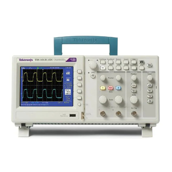
Operating Basics The front panel is divided into easy-to-use functional areas. This chapter provides you with a quick overview of the controls and the information displayed on the screen. 2-channel model 4-channel model Display Area In addition to displaying waveforms, the display is filled with many details about the waveform and the oscilloscope control settings. - Page 34 Operating Basics 1. Icon display shows acquisition mode. Sample mode Peak detect mode Average mode TDS2000C and TDS1000C-EDU Series Oscilloscope User Manual...
- Page 35 Operating Basics 2. Trigger status indicates the following: The oscilloscope is acquiring pretrigger data. All triggers are ignored in this state. All pretrigger data has been acquired and the oscilloscope is ready to accept a trigger. The oscilloscope has seen a trigger and is acquiring the posttrigger data.
-
Page 36: Using The Menu System
Operating Basics 14. Readout shows Edge or Pulse Width trigger level. 15. Display area shows helpful messages; some messages display for only three seconds. If you recall a saved waveform, readout shows information about the reference waveform, such as RefA 1.00V 500µs. 16. -
Page 37: Vertical Controls
Operating Basics 1 menu) button and then push the top option button to cycle through the Vertical (channel) Coupling options. In some lists, you can use the multipurpose knob to select an option. A hint line tells you when the multipurpose knob can be used, and an LED by the multipurpose knob lights when the knob is active. -
Page 38: Horizontal Controls
Operating Basics Position (1, 2, 3 & 4). Positions a waveform vertically. 1, 2, 3 & 4 Menu. Displays the Vertical menu selections and toggles the display of the channel waveform on and off. Scale (1, 2, 3 & 4). Selects vertical scale factors. Math. -
Page 39: Trigger Controls
Operating Basics Trigger Controls 4-channel model 2-channel model Level. When you use an Edge or Pulse trigger, the Level knob sets the amplitude level that the signal must cross to acquire a waveform. Trig Menu. Displays the Trigger Menu. Set To 50%. The trigger level is set to the vertical midpoint between the peaks of the trigger signal. - Page 40 Operating Basics Refer to the Reference chapter for detailed information on the menu and button controls. Multipurpose Knob. The function is determined by the displayed menu or selected menu option. When active, the adjacent LED lights. The next table lists the functions.
- Page 41 Operating Basics Active menu or option Knob function Description Vertical ► Probe ► Value entry For a channel menu (such as the CH Voltage ► Attenuation 1 menu), sets the attenuation factor in the oscilloscope Vertical ► Probe ► Value entry For a of channel menu (such as the Current ►...
-
Page 42: Input Connectors
Operating Basics Input Connectors 2-channel model 4-channel model 1, 2, 3 & 4. Input connectors for waveform display. Ext Trig. Input connector for an external trigger source. Use the Trigger Menu to select the Ext, or Ext/5 trigger source. Push and hold the Trig View button to see how the trigger settings affect the trigger signal, such as trigger coupling. -
Page 43: Understanding Oscilloscope Functions
Understanding Oscilloscope Functions This chapter contains general information that you need to understand before you use an oscilloscope. To use your oscilloscope effectively, you need to learn about the following functions: Setting up the oscilloscope Triggering Acquiring signals (waveforms) Scaling and positioning waveforms Measuring waveforms The next figure shows a block diagram of the various functions of the oscilloscope and their relationships to each other. -
Page 44: Triggering
Understanding Oscilloscope Functions Saving a Setup The oscilloscope saves the current setup if you wait five seconds after the last change before you power off the oscilloscope. The oscilloscope recalls this setup the next time you apply power. You can use the Save/Recall Menu to save up to ten different setups. You can also save setups to a USB flash drive. - Page 45 Understanding Oscilloscope Functions 4. Continues to acquire data until the waveform record is full. 5. Displays the newly-acquired waveform. NOTE. For Edge and Pulse triggers, the oscilloscope counts the rate at which trigger events occur to determine trigger frequency. The oscilloscope displays the frequency in the lower right corner of the screen.
-
Page 46: Acquiring Signals
Understanding Oscilloscope Functions Rising edge Falling edge Trigger level can be adjusted vertically Trigger can be rising or falling Acquiring Signals When you acquire a signal, the oscilloscope converts it into a digital form and displays a waveform. The acquisition mode defines how the signal is digitized, and the time base setting affects the time span and level of detail in the acquisition. -
Page 47: Scaling And Positioning Waveforms
Understanding Oscilloscope Functions Scaling and Positioning Waveforms You can change the display of waveforms by adjusting the scale and position. When you change the scale, the waveform display will increase or decrease in size. When you change the position, the waveform will move up, down, right, or left. The channel indicator (located on the left of the graticule) identifies each waveform on the display. - Page 48 Understanding Oscilloscope Functions the oscilloscope displays a waveform with a frequency lower than the actual input waveform, or triggers and displays an unstable waveform. Actual high-frequency waveform Apparent low-frequency waveform due to aliasing Sample points The oscilloscope accurately represents signals, but is limited by the probe bandwidth, the oscilloscope bandwidth, and the sample rate.
-
Page 49: Taking Measurements
Understanding Oscilloscope Functions Settings to avoid aliasing in Sample mode Time base Samples per second Maximum 2.5 ns 200.0 MHz † 2 GS/s 5.0 to 250.0 ns 1 GS/s or 2 GS/s 200.0 MHz † 500.0 ns 500.0 MS/s 200.0 MHz †... - Page 50 Understanding Oscilloscope Functions Graticule This method allows you to make a quick, visual estimate. For example, you might look at a waveform amplitude and determine that it is a little more than 100 mV. You can take simple measurements by counting the major and minor graticule divisions involved and multiplying by the scale factor.
- Page 51 Understanding Oscilloscope Functions Automatic measurements use readouts to show measurement results. These readouts are updated periodically as the oscilloscope acquires new data. For measurement descriptions, refer to the Reference chapter. (See page 89, Taking Measurements.) TDS2000C and TDS1000C-EDU Series Oscilloscope User Manual...
- Page 52 Understanding Oscilloscope Functions TDS2000C and TDS1000C-EDU Series Oscilloscope User Manual...
-
Page 53: Application Examples
Application Examples This section presents a series of application examples. These simplified examples highlight the features of the oscilloscope and give you ideas for using it to solve your own test problems. Taking simple measurements Using Autoset Using the Measure Menu to take automatic measurements Measuring two signals and calculating gain Using Autorange to examine a series of test points Taking cursor measurements... -
Page 54: Taking Simple Measurements
Application Examples Taking Simple Measurements You need to see a signal in a circuit, but you do not know the amplitude or frequency of the signal. You want to quickly display the signal and measure the frequency, period, and peak-to-peak amplitude. Using Autoset To quickly display a signal, follow these steps: 1. - Page 55 Application Examples Taking Automatic The oscilloscope can take automatic measurements of most displayed signals. Measurements NOTE. If a question mark (?) appears in the Value readout, the signal is outside the measurement range. Adjust the Vertical Scale knob (volts/division) of the appropriate channel to decrease the sensitivity or change the horizontal Scale setting (seconds/division).
- Page 56 Application Examples Freq 1.000kHz Period 1.000ms Pk-Pk 5.04V Rise Time 2.611µs? Pos Width 500.0µs TDS2000C and TDS1000C-EDU Series Oscilloscope User Manual...
- Page 57 Application Examples Measuring Two Signals If you are testing a piece of equipment and need to measure the gain of the audio amplifier, you will need an audio generator that can inject a test signal at the amplifier input. Connect two oscilloscope channels to the amplifier input and output as shown next.
- Page 58 Application Examples 7. Push the second option button from the top; the Measure 2 Menu appears. 8. Push Source ► CH2. 9. Push Type ► Pk-Pk. 10. Push the Back option button. Read the displayed peak-to-peak amplitudes for both channels. 11.
-
Page 59: Using Autorange To Examine A Series Of Test Points
Application Examples Using Autorange to Examine a Series of Test Points If you have a machine that is malfunctioning, you may need to find the frequency and RMS voltage of several test points, and compare these values to ideal values. You are not able to access front-panel controls since you need to use both hands when probing test points that are difficult to physically reach. -
Page 60: Taking Cursor Measurements
Application Examples Taking Cursor Measurements You can use the cursors to quickly take time and amplitude measurements on a waveform. Measuring Ring Frequency To measure the ring frequency at the rising edge of a signal, follow these steps: and Amplitude 1. - Page 61 Application Examples Type Amplitude Source ΔV 640mV Cursor 1 1.46V Cursor 2 820mV Measuring Pulse Width If you are analyzing a pulse waveform and you want to know the width of the pulse, follow these steps: 1. Push the Cursor button to see the Cursor Menu. 2.
- Page 62 Application Examples Type Time Source Δt 500.0µs 1/Δt 2.000kHz ΔV 1.38V Cursor 1 0.00s 0.98V Cursor 2 500µs -1.00V NOTE. The Positive Width measurement is available as an automatic measurement in the Measure Menu. (See page 89, Taking Measurements.) NOTE. The Positive Width measurement also displays when you select the Single-Cycle Square option in the AutoSet Menu.
- Page 63 Application Examples 11. Turn the multipurpose knob to place a cursor at the point where the waveform crosses the second graticule line below center screen. This is the 10% level of the waveform. 12. Push the Cursor 2 option button. 13.
-
Page 64: Analyzing Signal Detail
Application Examples Analyzing Signal Detail You have a noisy signal displayed on the oscilloscope and you need to know more about it. You suspect that the signal contains much more detail than you can now see in the display. Looking at a Noisy Signal The signal appears noisy and you suspect that noise is causing problems in your circuit. -
Page 65: Capturing A Single-Shot Signal
Application Examples Averaging reduces random noise and makes it easier to see detail in a signal. In the example below, a ring shows on the rising and falling edges of the signal when the noise is removed. Capturing a Single-Shot Signal The reliability of a reed relay in a piece of equipment has been poor and you need to investigate the problem. - Page 66 Application Examples Optimizing the Acquisition The initial acquisition shows the relay contact beginning to open at the trigger point. This is followed by a large spike that indicates contact bounce and inductance in the circuit. The inductance can cause contact arcing and premature relay failure.
-
Page 67: Measuring Propagation Delay
Application Examples Measuring Propagation Delay You suspect that the memory timing in a microprocessor circuit is marginal. Set up the oscilloscope to measure the propagation delay between the chip-select signal and the data output of the memory device. Type Time Source Δt 20.00ns 1/Δt 50.00MHz... -
Page 68: Triggering On A Specific Pulse Width
Application Examples 8. Push the Cursor 2 option button. 9. Turn the multipurpose knob to place the second cursor on the data output transition. The Δt readout in the Cursor Menu is the propagation delay between the waveforms. The readout is valid because the two waveforms have the same horizontal scale (seconds/division) setting. -
Page 69: Triggering On A Video Signal
Application Examples 1. Push the When option button to select ≠, <, or >. If there are any aberrant pulses that meet the specified When condition, the oscilloscope triggers. NOTE. The trigger frequency readout shows the frequency of events that the oscilloscope might consider to be a trigger, and may be less than the frequency of the input signal in Pulse Width trigger mode. - Page 70 To avoid amplitude inaccuracy from improper loading and reflections, place a 75 ohm feedthrough terminator (Tektronix part number 011-0055-02 or equivalent) between the 75 ohm coaxial cable from the signal source and the oscilloscope BNC input.
- Page 71 Application Examples Triggering on Video Lines Automatic. You can also look at the video lines in the field. To trigger on the video lines, follow these steps: 1. Push the AutoSet button. 2. Push the top option button to select Line to sync on all lines. (The AutoSet Menu includes All Lines and Line Number options.) Manual.
- Page 72 Application Examples Using the Window You can use the window (zoom) function to examine a specific portion of a waveform without changing the main display. Function to See Waveform Details If you want to view the color burst in the previous waveform in more detail without changing the main display, follow these steps: 1.
-
Page 73: Analyzing A Differential Communication Signal
Application Examples Analyzing a Differential Communication Signal You are having intermittent problems with a serial data communication link, and you suspect poor signal quality. Set up the oscilloscope to show you a snapshot of the serial data stream so you can verify the signal levels and transition times. Because this is a differential signal, you use the Math function of the oscilloscope to view a better representation of the waveform. -
Page 74: Viewing Impedance Changes In A Network
Application Examples 6. Push the Operation option button and select -. 7. Push the CH1-CH2 option button to display a new waveform that is the difference between the displayed waveforms. 8. To adjust the vertical scale and position of the Math waveform, follow these steps: a. - Page 75 Application Examples To view the input and output of the circuit in an XY display, follow these steps: 1. Push the 1 (channel 1 menu) button. 2. Push Probe ► Voltage ►Attenuation ► 10X. 3. Push the 2 (channel 2 menu) button. 4.
-
Page 76: Data Logging (Not Available On Tds1000C-Edu Models)
Application Examples 11. Turn the vertical Scale and vertical Position knobs to optimize the display. 12. Push Persist ► Infinite. As you adjust the ambient temperature, the display persistence captures the changes in the characteristics of the circuit. Data Logging (not available on TDS1000C-EDU models) You want to use the oscilloscope to record data from a source over time. -
Page 77: Limit Testing (Not Available On Tds1000C-Edu Models)
Application Examples Limit Testing (not available on TDS1000C-EDU models) You want to use the oscilloscope to monitor an active input signal against a template and to output pass or fail results by judging whether the input signal is within the bounds of the template. 1. - Page 78 Application Examples of waveforms, number of violations, or the time in seconds at which to stop. You can also choose to stop the testing manually. 8. Push the Run/Stop Test button to toggle between starting and ending the limit test. After you end the test, the oscilloscope will display the test statistics on the screen.
-
Page 79: Math Fft
Math FFT This chapter contains detailed information on how to use the Math FFT (Fast Fourier Transform). You can use the FFT Math mode to convert a time-domain (YT) signal into its frequency components (spectrum). You can use the Math FFT mode for the following types of analysis: Analyze harmonics in power lines Measure harmonic content and distortion in systems... - Page 80 Math FFT 4. Turn the Vertical Scale (volts/division) knob to ensure that the entire waveform remains on the screen. The oscilloscope may display erroneous FFT results (by adding high frequency components) if the entire waveform is not visible. 5. Turn the Horizontal Scale (seconds/division) knob to provide the resolution you want in the FFT spectrum.
-
Page 81: Displaying The Fft Spectrum
Math FFT Displaying the FFT Spectrum Push the Math button to display the Math Menu. Use the options to select the Source channel, Window algorithm, and FFT Zoom factor. You can display only one FFT spectrum at a time. Math FFT option Settings Comments Source... -
Page 82: Selecting An Fft Window
Math FFT Selecting an FFT Window Windows reduce spectral leakage in the FFT spectrum. The FFT assumes that the YT waveform repeats forever. With an integral number of cycles (1, 2, 3, ...), the YT waveform starts and ends at the same amplitude and there are no discontinuities in the signal shape. - Page 83 Math FFT The Math FFT function includes three FFT Window options. There is a trade-off between frequency resolution and amplitude accuracy with each type of window. What you want to measure and your source signal characteristics will help you to determine which window to use.
- Page 84 Math FFT TDS2000C and TDS1000C-EDU Series Oscilloscope User Manual...
-
Page 85: Magnifying And Positioning An Fft Spectrum
Math FFT Eliminating Aliases To eliminate aliases, try the following remedies: Turn the Horizontal Scale (seconds/division) knob to set the sample rate to a faster setting. Since you increase the Nyquist frequency as you increase the sample rate, the aliased frequency components appear at their proper frequency. -
Page 86: Measuring An Fft Spectrum Using Cursors
Math FFT Measuring an FFT Spectrum Using Cursors You can take two measurements on FFT spectrums: magnitude (in dB), and frequency (in Hz). Magnitude is referenced to 0 dB, where 0 dB equals 1 V You can use the cursors to take measurements at any zoom factor. To do so, follow these steps: 1. -
Page 87: Usb Flash Drive And Device Ports
USB Flash Drive and Device Ports This chapter describes how to use the Universal Serial Bus (USB) ports on the oscilloscope to do the following tasks: Save and recall waveform data or setup data, or save a screen image Print a screen image Transfer waveform data, setup data, or a screen image to a PC Control the oscilloscope with remote commands To use the PC Communications software, launch and refer to the online help... -
Page 88: File Management Conventions
USB Flash Drive and Device Ports To remove a USB flash drive, wait until the LED on the drive (if any) stops blinking or until the hint line appears that says the operation is complete, grab the edge of the drive, and extract the drive from the port. Flash Drive Initial Read The oscilloscope reads the internal structure of a USB flash drive each time you install a drive. -
Page 89: Saving And Recalling Files With A Usb Flash Drive
USB Flash Drive and Device Ports A:\ is the root folder. The oscilloscope resets the current folder to A:\ when you power on the oscilloscope, or when you insert a USB flash drive after the oscilloscope is powered on. File names can have one to eight characters, followed by a period, and then followed with an extension of one to three characters. - Page 90 USB Flash Drive and Device Ports Save Image, Save Setup, You can save a screen image, the oscilloscope settings, or waveform data to a file on the USB flash drive through the Save/Recall menu. and Save Waveform Options Each save option operates in a similar way. As an example, to save a screen image file to a flash drive, follow these steps: 1.
-
Page 91: Using The Save Function Of The Print Front Panel Button
USB Flash Drive and Device Ports 5. Select the To option and specify which reference memory location to recall the waveform to RefA or RefB. RefC and RefD are available on 4-channel models. 6. Push the Recall FnnnnCHx.CSV option button, where FnnnnCHx.CSV is the name of the waveform file. - Page 92 USB Flash Drive and Device Ports The oscilloscope creates a new folder on the flash drive and saves the screen image, waveform data, and setup data in separate files in that new folder, using the current oscilloscope and file format settings. The oscilloscope names the folder ALLnnnn.
-
Page 93: Usb Device Port
USB Flash Drive and Device Ports File format Extension Comments Run-length encoding; this format uses a lossless compression algorithm. TIFF Tagged Image File Format Before you can save data to the USB flash drive, you must change the print button to the alternative Save function. -
Page 94: Installing The Pc Communications Software On A Pc
Software for your oscilloscope is also available through the Software finder on the Tektronix web site. To install the PC Communications software, follow these steps: 1. Insert the CD-ROM that came with your oscilloscope into the CD drive on the PC. - Page 95 Do NOT search for the hardware to install on the web. 6. For a Windows XP systems, follow these steps: a. If you see the Tektronix PictBridge Device dialog box, click Cancel. b. When prompted, select the option that tells Windows NOT to connect to Windows Update, and click Next.
-
Page 96: Connecting To A Gpib System
USB Flash Drive and Device Ports Unplug the USB cable from your oscilloscope, and install the software from the CD that came with your oscilloscope. Reconnect your oscilloscope to the PC and follow steps 7a, 7b, and 7c. 8. When prompted, click Finish. 9. -
Page 97: Connecting To A Printer
USB Flash Drive and Device Ports Connecting to a Printer When you connect the oscilloscope to a PictBridge compatible printer, the oscilloscope and printer can be powered on or off. To connect the oscilloscope to a PictBridge compatible printer, follow these steps: 1. - Page 98 USB Flash Drive and Device Ports 6. If printing fails, check that the USB cable is connected to the PictBridge port on the printer, and try again. NOTE. The oscilloscope stores these settings until you change them, even if you push the Default Setup button, or you power off the oscilloscope.
-
Page 99: Reference
Reference This chapter describes the menus and operating details associated with each front-panel menu button or control. Acquire Push the Acquire button to set acquisition parameters. Options Settings Comments Sample Use to acquire and accurately display most waveforms; this is the default mode Peak Detect Use to detect glitches and reduce the possibility of aliasing... - Page 100 Reference Maximum of 500 MS/s for 40 MHz and 50 MHz models Maximum of 1 GS/s for 60 MHz, 70 MHz or 100 MHz models Maximum of 2 GS/s for 200 MHz models At 100 ns and faster settings, this sample rate does not acquire 2500 points. In this case, a Digital Signal Processor interpolates points between the sampled points to make a 2500 point waveform record.
-
Page 101: Autorange
Reference Run/Stop Button. Push the Run/Stop button when you want the oscilloscope to continuously acquire waveforms. Push the button again to stop the acquisition. Single Button. Push the Single (single sequence) button when you want the oscilloscope to acquire a single waveform and then stop. Each time you push the Single button, the oscilloscope begins to acquire another waveform. - Page 102 Reference Options Comment Horizontal Only Tracks and adjusts the Horizontal scale; does not change the vertical settings Undo Autoranging Causes the oscilloscope to recall the previous setup The following conditions cause autorange to adjust settings: Too many or too few waveform periods for a clear display of the trigger source (except when in Vertical Only) Waveform amplitude too large or too small (except when in Horizontal Only) Ideal trigger level changes...
-
Page 103: Autoset
Reference XY Display format Persistence The Autorange function is usually more useful than Autoset in the following situations: Analyzing a dynamically changing signal Quickly comparing a sequence of several signals without adjusting the oscilloscope. This is very useful if you need to use two probes at the same time, or if you need to use a probe in one hand and are holding something else in the other. - Page 104 Reference Function Setting Trigger Video Sync Adjusted Trigger Video Standard Adjusted Vertical bandwidth Full Vertical coupling DC (if GND was previously selected); AC for a video signal; otherwise, unchanged VOLTS/DIV Adjusted The Autoset function examines all channels for signals and displays corresponding waveforms.
- Page 105 Reference Sine wave Details Converts the input time-domain signal into its frequency components and displays the result as a graph of frequency versus magnitude (spectrum); because this is a mathematical calculation, refer to the Math FFT chapter for more information Undo Autoset Causes the oscilloscope to recall the previous setup Square Wave or Pulse...
-
Page 106: Cursor
Reference Video signal options Details Displays several fields and the oscilloscope triggers only on even numbered fields Even Fields Undo Autoset Causes the oscilloscope to recall the previous setup NOTE. Video autoset sets the Display Type option to Dot Mode. Cursor Push the Cursor button to display the measurement cursors and Cursor Menu, and then use the multipurpose knob to change the position of a cursor. -
Page 107: Default Setup
Reference Key Points Cursor Movement. Use the multipurpose knob to move Cursor 1 or Cursor 2. You can move the cursors only while the Cursor Menu is displayed. The active cursor is represented by a solid line. Amplitude cursors Time cursors Default Setup Push the Default Setup button to recall most of the factory option and control settings, but not all. - Page 108 Reference 1. A solid waveform indicates a channel (live) waveform display. The waveform remains solid when the acquisition is stopped if no controls are changed that make the display accuracy uncertain. Changing the vertical and horizontal controls is allowed on stopped acquisitions.
- Page 109 Reference channel 2 is the vertical axis. The oscilloscope uses the untriggered Sample acquisition mode and displays data as dots. The sampling rate is fixed at 1 MS/s. NOTE. The oscilloscope can capture a waveform in normal YT mode at any sampling rate.
-
Page 110: Help
Reference Help Push the Help button to display the Help menu. The topics cover all the menu options and controls of the oscilloscope. (See page xiv, Help System.) Horizontal You can use the horizontal controls to set up two views of a waveform, each with their own horizontal scale and position. -
Page 111: Math
Reference Key Points Horizontal Scale. If waveform acquisition is stopped (using the Run/Stop or Single button), the Horizontal Scale control expands or compresses the waveform. Use to zoom in on a detail of the waveform. Scan Mode Display (Roll Mode). When the Horizontal Scale control is set to 100 ms/div or slower and the trigger mode is set to Auto, the oscilloscope enters the Scan acquisition mode. - Page 112 Reference Options Comments Position Use the multipurpose knob to set the vertical position of the resultant Math waveform Vertical Scale Use the multipurpose knob to set the vertical scale of the resultant Math waveform The Math Menu includes Sources options for each operation. Operation Sources option Comments...
-
Page 113: Measure
Reference Measure Push the Measure button to access automatic measurements. There are sixteen types of measurements available. You can display up to five at a time. Push the top option button to display the Measure 1 Menu. You can choose the channel on which to take a measurement in the Source option. -
Page 114: Print
Reference Print When the Save All ► PRINT Button option is set to Prints, you can push the print button to send the screen image to a printer. You can set up the oscilloscope to send a screen image to your printer through the Utility ►... -
Page 115: Probe Check
Reference Probe Check You can use the Probe Check Wizard to quickly verify that your voltage probe is operating properly. (See page 5, Voltage Probe Check Wizard.) Reference Menu The Reference menu can turn on or turn off reference memory waveforms from the display. - Page 116 Reference Action options Comments Save Setup Saves the current oscilloscope settings to a file in a specified folder or in nonvolatile setup memory Save Waveform Saves the specified waveform to a file or to reference memory Recall Setup Recalls an oscilloscope setup file from a USB flash drive or from a location in nonvolatile setup memory Recall Waveform Recalls a waveform file from a USB flash drive to reference memory...
- Page 117 Reference Options Settings or submenus Comments Select Folder Lists the contents of the current USB flash drive folder and displays the folder options Change Folder (See page 64, File Management Conventions.) (See page 103, File New Folder Utilities for the USB Flash Drive.) Layout , Portrait, Select portrait or landscape image...
- Page 118 Reference Save Waveform The Save Waveform action saves the specified waveform to a file named TEKnnnn.CSV, or to reference memory. The oscilloscope saves waveform data to files as "comma separated values" (.CSV format), which are ASCII text strings that list the time (relative to the trigger) and amplitude values for each of the 2500 waveform data points.
- Page 119 Reference Recall Waveform The Recall Waveform action recalls a waveform file from a USB flash drive to a location in reference memory. Options Settings or submenus Comments Ref(x) Specifies the reference memory location to load the waveform to From File Recalls the file from the USB flash drive Select File Lists the contents of the current USB...
-
Page 120: Trigger Controls
Reference Trigger Controls You can define the trigger through the Trigger Menu and front-panel controls. Trigger Types Three types of triggering are available: Edge, Video, and Pulse Width. A different set of options display for each type of trigger. Option Details Edge (default) Triggers the oscilloscope on the rising or falling edge of the input... - Page 121 Reference scale setting. You can use this mode in many situations, such as to monitor the level of a power supply output. Use the Auto mode to let the acquisition free-run in the absence of a valid trigger. This mode allows an untriggered, scanning waveform at 100 ms/div or slower time base settings.
- Page 122 Reference Option Details HF Reject Attenuates the high-frequency components above 80 kHz LF Reject Blocks the DC component and attenuates the low-frequency components below 300 kHz Blocks DC components and attenuates signals below 10 Hz NOTE. Trigger coupling affects only the signal passed to the trigger system. It does not affect the bandwidth or coupling of the signal displayed on the screen.
- Page 123 Reference Pulse Width Trigger Use Pulse Width triggering to trigger on normal or aberrant pulses. Options Settings Comments Pulse With Pulse highlighted, triggering occurs on pulses that meet the trigger condition defined by the Source, When, and Set Pulse Width options Source CH1, CH2, CH3 , CH 4...
- Page 124 Reference Refer to the Application Examples chapter for an example of triggering on aberrant pulses. (See page 44, Triggering on a Specific Pulse Width.) Knobs and Buttons Level Knob. Use to control the Trigger Level. Set To 50% Button. Use the Set To 50% button to quickly stabilize a waveform. The oscilloscope automatically sets the Trigger Level to be about halfway between the minimum and maximum voltage levels.
-
Page 125: Utility
Reference Holdoff. You can use the Trigger Holdoff function to produce a stable display of complex waveforms, such as pulse trains. Holdoff is the time between when the oscilloscope detects one trigger and when it is ready to detect another. The oscilloscope will not trigger during the holdoff time. - Page 126 Sets the date and time (See page 102.) Error Log Displays a list of any errors logged and the Power Cycle count This log is useful if you contact a Tektronix Service Center for help. Do Self Cal Performs a self calibration File Utilities Displays folder, file, and USB flash drive options (See...
- Page 127 Follow the directions on the screen. Factory calibration uses externally-generated voltages, and requires specialized equipment. The recommended interval is one year. See Contacting Tektronix on the copyright page for information on having Tektronix perform a Factory Calibration of your oscilloscope. File Utilities for the USB One folder is always designated as the current folder.
-
Page 128: Vertical Controls
Reference Options Comments Confirm Delete Displays after pressing Delete, to confirm a file delete action. Pressing any button or knob other than Confirm Delete cancels the file delete action. Format Formats the USB flash drive; this deletes all data on the USB flash drive. - Page 129 Reference Options Settings Comments BW Limit 20 MHz , Off Limits the bandwidth to reduce display noise; filters the signal to reduce noise and other unwanted high frequency components Volts/Div Coarse, Fine Selects the resolution of the Scale (Volts/Div) knob Coarse defines a 1-2-5 sequence.
- Page 130 Reference Remove Waveform. To remove a waveform from the display, push a channel menu front panel button. For example, push the 1 (channel 1 menu) button to display or remove the channel 1 waveform. NOTE. You do not have to display a channel waveform to use it as a trigger source or for math operations.
-
Page 131: Appendix A: Specifications
Appendix A: Specifications All specifications apply to the TDS2000C and TDS1000C-EDU series models. TPP0101 and TPP0201 probe specifications appear in Appendix B. To verify that the oscilloscope meets specifications, the oscilloscope must first meet the following conditions: The oscilloscope must have been operating continuously for twenty minutes within the specified operating temperature. - Page 132 Appendix A: Specifications Table 2: Input Specifications (cont.) Characteristic Description Maximum Input Voltage At front panel connector, 300 V RMS, Installation Category II; derate at 20 dB/decade above 100 kHz to 13 V peak AC at 3 MHz and above. Based upon sinusoidal or DC input signal.
- Page 133 Appendix A: Specifications Table 3: Vertical Specifications (cont.) Characteristic Description Analog Bandwidth, DC V/div values are accurate for probe attenuation settings of 1X. No probe should be installed for these measurements. Coupled, Sample or TDS2001C TDS2002C, 2004C TDS1012C-EDU, TDS2022C, 2024C Average TDS2012C, 2014C DC to >50 MHz for 5 mV/div...
- Page 134 Appendix A: Specifications Table 3: Vertical Specifications (cont.) Characteristic Description DC Voltage Measurement The accuracy of DC voltage measurements acquired using Average of ≥ 16 waveforms. Accuracy, Average Vertical Position = 0 ±(3% of |reading| + 0.1 div + 1 mV). Acquisition Mode Vertical Position ≠...
- Page 135 Appendix A: Specifications Table 5: Trigger Specifications Characteristic Description Sensitivity, Edge-Type Trigger Source Sensitivity (Measurement style A) Sensitivity (Measurement style B) Trigger, DC Coupled Channel Inputs All Products 1.5 div from DC to 10 MHz 1 div from DC to 10 MHz (>2 mV/div) (>2 mV/div) 2.5 div from DC to 10 MHz 4 div from DC to 10 MHz (2 mV/div)
- Page 136 Appendix A: Specifications Table 5: Trigger Specifications (cont.) Characteristic Description Video Trigger Sensitivity, A 2 division composite video signal will have a 0.6 division sync tip. typical The typical sensitivities are as follows: Source Typical Sensitivity Input Channels 2 divisions of composite video 400 mV of composite video EXT/5 2 V of composite video...
-
Page 137: Power Source
Appendix A: Specifications Table 6: General Specifications Characteristic Description Display Display Type 11.5 cm (W) x 8.64 cm (H), 14.38 cm diagonal, ¼ VGA, active TFT color liquid crystal display (LCD) with color characters/waveforms on a black background. Surface anti-glare (3H) treatment Display Resolution 320 horizontal by 240 vertical pixels The video display comprises both the character and waveform displays. - Page 138 Appendix A: Specifications TDS2000C and TDS1000C-EDU Series Oscilloscope User Manual...
-
Page 139: Appendix B: Tpp0101 And Tpp0201 Series 10X Passive Probes Information
Tektronix oscilloscopes: TDS1000C-EDU/TDS2000C oscilloscopes that have 20 pF of input capacitance. The compensation range of these probes is 15–25 pF. The probes have no user- or Tektronix-serviceable parts. WARNING. Do not float the TPP0101 and TPP0201 probes on any oscilloscope. -
Page 140: Connecting The Probe To The Circuit
Appendix B: TPP0101 and TPP0201 Series 10X Passive Probes Information 1. Connect the probe to the oscilloscope channel that you plan to use for your measurements. 2. Connect the probe to the probe compensation output terminals on the oscilloscope front panel. WARNING. -
Page 141: Standard Accessories
Item Description Color bands Use these bands to identify the oscilloscope channel at the probe head. Reorder Tektronix part number 016-0633-xx (5 pairs) Hook tip Press the hook tip onto probe tip and then clamp the hook onto the circuit. -
Page 142: Optional Accessories
Appendix B: TPP0101 and TPP0201 Series 10X Passive Probes Information Optional Accessories You can order the following accessories for your probe. Accessory Part number Alligator Ground Lead, 12 in 196-3512-xx 6” Clip-on Ground Lead 196-3198-xx Ground Spring, Short, 2 ea. 016-2034-xx MicroCKT Test Tip 206-0569-xx... -
Page 143: Performance Graphs
Appendix B: TPP0101 and TPP0201 Series 10X Passive Probes Information Performance Graphs Table 9: Certifications and compliances Characteristics Description EC Declaration of Compliance was demonstrated to the following specification as listed Conformity in the Official Journal of the European Communities: Low Voltage Directive 2006/95/EC: EN61010-031: 2002 UL61010-031;2007... -
Page 144: Safety Summary
Directive 2002/96/EC on waste electrical and electronic equipment (WEEE). For more information about recycling options, check the Support/Service section of the Tektronix Web site (www.tektronix.com). Safety Summary Review the following safety precautions to avoid injury and prevent damage to this product or any products connected to it. - Page 145 Appendix B: TPP0101 and TPP0201 Series 10X Passive Probes Information Do Not Operate in Wet/Damp Conditions. Do Not Operate in an Explosive Atmosphere. Keep Product Surfaces Clean and Dry. Safety Terms and Symbols These terms may appear in this manual: Terms in This Manual.
- Page 146 Appendix B: TPP0101 and TPP0201 Series 10X Passive Probes Information TDS2000C and TDS1000C-EDU Series Oscilloscope User Manual...
-
Page 147: Appendix C: Accessories
Appendix C: Accessories All accessories (standard and optional) are available by contacting your local Tektronix field office. Standard Accessories TPP0101 or TPP0201, 10X Passive Voltage Probe. The TPP0101 probes have a system bandwidth of DC to 100 MHz at -3 dB and ship standard with TDS2000C oscilloscope models that have bandwidths <100 MHz and with all TDS1000C-EDU... - Page 148 Appendix C: Accessories TDS2000C and TPS2000 Series Digital Oscilloscopes Programmer Manual . The programmer manual (077-0444-XX, English) provides command and syntax information. TDS2000C Series Digital Storage Oscilloscope Service Manual. The service manual (077-0446-XX, English) provides module-level repair information. TDS2000C and TDS1000C-EDU Series Digital Storage Oscilloscope User Manuals.
-
Page 149: Appendix D: Cleaning
Appendix D: Cleaning General Care Do not store or leave the oscilloscope where the LCD display will be exposed to direct sunlight for long periods of time. CAUTION. To avoid damage to the oscilloscope or probes, do not expose them to sprays, liquids, or solvents. - Page 150 Appendix D: Cleaning TDS2000C and TDS1000C-EDU Series Oscilloscope User Manual...
-
Page 151: Appendix E: Default Setup
Appendix E: Default Setup This appendix describes the options, buttons and controls that change settings when you push the Default Setup button. The last page of this appendix lists settings that do not change. NOTE. When you push the Default Setup button, the oscilloscope displays the CH1 waveform and removes all other waveforms. - Page 152 Appendix E: Default Setup Menu or system Option, button, or knob Default setting TRIGGER (Edge) Slope Rising Mode Auto Coupling Level 0.00 V TRIGGER (Video) Polarity Normal Sync All Lines Standard NTSC TRIGGER (Pulse) When Set Pulse Width 1.00 ms Polarity Positive Mode...
-
Page 153: Appendix F: Font Licenses
Appendix F: Font Licenses The following license agreements cover Asian fonts used in the TDS2000C and TDS1000C-EDU series oscilloscopes. Copyright © 1988 The Institute of Software, Academia Sinica. Correspondence Address: P.O.Box 8718, Beijing, China 100080. Permission to use, copy, modify, and distribute this software and its documentation for any purpose and without fee is hereby granted, provided that the above copyright notices appear in all copies and that both those copyright notices and this permission notice appear in supporting documentation, and that the name... - Page 154 Appendix F: Font Licenses Redistribution and use in source and binary forms, with or without modification, are permitted provided that the following conditions are met: Redistribution of source code must retain the above copyright notice, this list of conditions and the following disclaimer. Redistributions in binary form must reproduce the above copyright notice, this list of conditions and the following disclaimer in the documentation and/or other materials provided with the distribution.
- Page 155 Index Symbols and Numbers averaging, using, 40 Autorange functions, 19 calculating amplifier gain, 34 overview, 77 1, 2, 3, or 4 capturing a single-shot turning off, 78 channel connectors, 18 signal, 41 Autorange menu, 77 channel menu buttons, 14 cursors, using, 36 AutoSet data logging, 52 button, 17...
- Page 156 Index Channel coupling, 104 Data logging Edge trigger, 96 menu, 104 application example, 52 EPSIMAGE file format, 68 scale, 11 Date, 102 Error Log, 102 Cleaning, 125 Date and time readout, 12 Ext Trig connector, 18 Clock DC coupling probe compensation, 6 set date and time, 102 trigger, 96 Coarse resolution, 105...
- Page 157 Index Firmware update Horizontal Internet, xv aliasing, time domain, 23 Icons Firmware updates, 104 menu, 86 acquisition modes, Flattop window, 59 position, 23 Average, 10 Folders position marker, 11 acquisition modes, Peak creating, 103 scale, 23 Detect, 10 deleting, 100, 103 Scan mode, 77, 87 acquisition modes, renaming, 104...
- Page 158 Index Interpolation, 76 Measurements Messages, 12 Inverted waveform automatic, 26, 89 Minimum measurements, 89 readout, 11 basic concepts, 25 Multiply waveforms cursor, 26, 36 Math menu, 87 cursor RMS, 89 Multipurpose knob, 16 cycle RMS, 89 JPG file format, 68 delay, 89 duty cycle, 89 Navigation...
- Page 159 Index Panning Printing Reference waveforms horizontal, 23 abort, 74, 90 displaying and removing, 91 vertical, 23 screen data, 90 readout, 12 screen image, 73 saving and recalling, 95 connecting to an PROBE CHECK button, 6 Remote control using a oscilloscope, 70 Probe Check Wizard GPIB interface, 72 PCX file format, 68...
- Page 160 Index Saving Source Trigger all files to a USB flash AC Line, 98 coupling, 21, 96, 97 drive, 67 Ext, 97 definition, 20 image files to a USB flash Ext/5, 97 edge, 96 drive, 68 trigger, 21, 96, 98, 99 force, 100 setups, 95 Specifications...
- Page 161 Index Utility menus, 101 Windows FFT spectrum, 58 W indicator for Window time base, 86 Waveforms Vectors, 83 acquire data, 22 Ventilation, 3 compression, 87 Vertical application example, 51 digitized, 22 menu, 104 display format, 83, 84 display style meaning, 83 position, 23 expansion, 87 position knob, 14...
Need help?
Do you have a question about the TDS2000C series and is the answer not in the manual?
Questions and answers