Tektronix TDS 2012 User Manual
Digital storage oscilloscope
Hide thumbs
Also See for TDS 2012:
- Programmer's manual (250 pages) ,
- User manual (207 pages) ,
- Manual (139 pages)

Related Manuals for Tektronix TDS 2012


Summary of Contents for Tektronix TDS 2012
- Page 1 1/18 tds2012_oscilloscope_guide.doc Tektronix TDS 2012 Digital Storage Oscilloscope User’s Guide Authors/Contributors: Thomas Montoya James Free Jake Gunderson John Preheim Dr. Montoya Rev. 3/16/09...
-
Page 2: Table Of Contents
2/18 tds2012_oscilloscope_guide.doc Table of Contents Background/Introduction ……………………………………………………. 3 Simple voltage measurement and display …………………………………. .. 4 Printing oscilloscope display ………………………………………………. .. 4 Default setup ………………………………………………………………..4 Autoset ………………………………………………………………………. 4 Channel menus ……………………………………………………………..5 Volts/Div knobs ……………………………………………………………... 5 Sec/Div knob ………………………………………………………………. .. 5 Position knobs ……………………………………………………………... -
Page 3: Background/Introduction
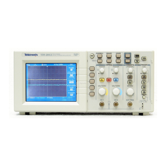
Background/Introduction This guide discusses using the Tektronix TDS 2012 Digital Storage Oscilloscopes to make simple voltage versus time measurements and perform/use elementary functions. Figure 1 shows the front panel of the oscilloscope. Digital storage oscilloscopes sample analog signals, store the values (and corresponding times), and display them on the screen. -
Page 4: Simple Voltage Measurement And Display
4/18 tds2012_oscilloscope_guide.doc Simple voltage measurement and display For the simplest case of a single self-triggering measurement, connect a P2200 passive probe to the CH1 BNC connector and the tip of the probe to the component/device whose voltage is to be measured. -
Page 5: Channel Menus
5/18 tds2012_oscilloscope_guide.doc Channel menus The yellow CH1 MENU and blue CH2 MENU buttons are used to cause the oscilloscope to either display or hide the signal from the corresponding channel (yellow trace for CH1 and blue trace for CH2). In addition, when the particular channel is selected, a softkey menu for that channel will be activated. -
Page 6: Set To Zero
6/18 tds2012_oscilloscope_guide.doc Set to zero Under the “HORIZONTAL” menu, the SET TO ZERO button sets the horizontal position (controlled by the horizontal position knob) to zero (center vertical axis), thus centering the signal horizontally. Help The oscilloscope has a Help system with topics that cover all the features of the oscilloscope. You can use the Help system to display several kinds of information: 1) general information about understanding and using the oscilloscope, 2) information about specific menus and controls, and 3) device about problems you may face while using an oscilloscope (e.g., reducing... -
Page 7: Math Menu
7/18 tds2012_oscilloscope_guide.doc Table 1 Horizontal Menu choices The axis for vertical scale is the ground level. A readout near the top right of the screen displays the current horizontal position in seconds. An M indicates the Main time base and a W indicates the Window time base. -
Page 8: Save/Recall
8/18 tds2012_oscilloscope_guide.doc The + and - options will display the sum or difference of the two signals on the display. It is important to note that the sum or difference will be calculated using the visual signals on the display. This means that if one signal is displayed to a higher magnification level (i.e., different VOLTS/DIV setting) than the other, the result will not be a true sum or difference. -
Page 9: Measure
9/18 tds2012_oscilloscope_guide.doc You can choose an FFT window to eliminate discontinuities that will disrupt your output. As shown in Table 3, there are three window choices. Table 3 FFT window options Problems occur when the oscilloscope acquires a time-domain waveform containing frequency components that are greater than the Nyquist frequency. -
Page 10: Menus
10/18 tds2012_oscilloscope_guide.doc There are several options for eliminating aliasing: 1. Adjust the Sec/Div control to a faster setting. This will raise the Nyquist frequency and bring the FFT display within range of the aliases. 2. If you do not need to view frequencies components above 20 MHz, set the Bandwidth Limit option to On. -
Page 11: Utility
11/18 tds2012_oscilloscope_guide.doc Table 4 Save/Recall button Setups options Table 5 Save/Recall button Waveforms options 2) Push the MEASURE button to access automatic measurements. Each of the five softkeys is available to have a measurement source and type defined. For example, pressing the top softkey will bring up a “Measure 1”... - Page 12 12/18 tds2012_oscilloscope_guide.doc Table 6 Types of measurements 3) Push the ACQUIRE button to bring up a softkey menu with the selections listed in Table 7. Table 7 ACQUIRE softkey menu Dr. Montoya Rev. 3/16/09...
-
Page 13: Cursor
13/18 tds2012_oscilloscope_guide.doc 4) Push the UTILITY button to bring up a softkey menu with the selections listed in the first column of Table 8. Some these selections bring up subchoices as listed in the second column of Table 8. Table 8 UTILITY softkey menu Dr. - Page 14 14/18 tds2012_oscilloscope_guide.doc 5) Push the CURSOR button to bring up a “CURSOR” softkey menu with a <Type> softkey and <Source> softkey. As shown in Table 9, pushing the <Type> softkey will toggle the user between selections of Voltage, Time, and Off. As shown in Table 9, pushing the <Source>...
-
Page 15: Display
15/18 tds2012_oscilloscope_guide.doc 6) Push the DISPLAY button to bring up a softkey menu with the selections listed in Table 10. Table 10 DISPLAY softkey menu Trigger Controls You can define the trigger (see Table 11) by pushing the TRIG MENU button and front-panel soft keys. -
Page 16: Edge Trigger
16/18 tds2012_oscilloscope_guide.doc Dr. Montoya Rev. 3/16/09... -
Page 17: Video Trigger
17/18 tds2012_oscilloscope_guide.doc Dr. Montoya Rev. 3/16/09... -
Page 18: Pulse Width Trigger
18/18 tds2012_oscilloscope_guide.doc Other Trigger Controls Level Dial Use to select which point on the wave to set the trigger. SET TO 50% The trigger level is set to the vertical midpoint between the peaks of the trigger signal. FORCE TRIG Completes an acquisition regardless of an adequate trigger signal. This button has no effect if the acquisition is already stopped.
Need help?
Do you have a question about the TDS 2012 and is the answer not in the manual?
Questions and answers