Tektronix TDS 200 Series Service Manual
Digital real-time oscilloscope
Hide thumbs
Also See for TDS 200 Series:
- Programmer's manual (346 pages) ,
- Operator training kit manual (235 pages) ,
- Instructions manual (56 pages)
Table of Contents
Advertisement
Service Manual
TDS 200-Series
Digital Real-Time Oscilloscope
071-0492-02
This document supports firmware version 1.00
and above.
Warning
The servicing instructions are for use by
qualified personnel only. To avoid personal
injury, do not perform any servicing unless you
are qualified to do so. Refer to all safety
summaries prior to performing service.
www.tektronix.com
Advertisement
Chapters
Table of Contents

Subscribe to Our Youtube Channel
Related Manuals for Tektronix TDS 200 Series


Summary of Contents for Tektronix TDS 200 Series
- Page 1 This document supports firmware version 1.00 and above. Warning The servicing instructions are for use by qualified personnel only. To avoid personal injury, do not perform any servicing unless you are qualified to do so. Refer to all safety summaries prior to performing service. www.tektronix.com...
- Page 2 Copyright © Tektronix, Inc. All rights reserved. Tektronix products are covered by U.S. and foreign patents, issued and pending. Information in this publication supercedes that in all previously published material. Specifications and price change privileges reserved. Tektronix, Inc., P.O. Box 500, Beaverton, OR 97077...
- Page 3 Tektronix, shipping charges prepaid, and with a copy of customer proof of purchase. Tektronix shall pay for the return of the product to Customer if the shipment is to a location within the country in which the Tektronix service center is located.
- Page 5 ..........5–2 TDS 200 Series Digital Oscilloscope Service Manual...
-
Page 6: Table Of Contents
........10–2 TDS 200 Series Digital Oscilloscope Service Manual... - Page 7 Figure 10–1: Exploded diagram ....... 10–7 TDS 200 Series Digital Oscilloscope Service Manual...
- Page 8 ....10–8 Table 10–5: Replaceable optional accessories ....10–8 TDS 200 Series Digital Oscilloscope Service Manual...
- Page 9 Provide Proper Ventilation. To prevent product overheating, provide proper ventilation. Do Not Operate With Suspected Failures. If you suspect there is damage to this product, have it inspected by qualified service personnel. TDS 200 Series Digital Oscilloscope Service Manual...
- Page 10 DANGER Protective Ground ATTENTION Double High Voltage (Earth) Terminal Refer to Manual Insulated Certifications and Refer to the specifications section for a listing of certifications and compliances Compliances that apply to this product. TDS 200 Series Digital Oscilloscope Service Manual...
- Page 11 Use Care When Servicing With Power On. Dangerous voltages or currents may exist in this product. Disconnect power, remove battery (if applicable), and disconnect test leads before removing protective panels, soldering, or replacing components. To avoid electric shock, do not touch exposed connections. TDS 200 Series Digital Oscilloscope Service Manual...
- Page 12 Service Safety Summary viii TDS 200 Series Digital Oscilloscope Service Manual...
- Page 13 Spanish 071-0399-XX* 071-0482-XX Portuguese 071-0403-XX* 071-0486-XX Japanese 071-0405-XX* 071-0488-XX Korean 071-0408-XX* 071-0491-XX Simplified Chinese 071-0406-XX* 071-0489-XX Traditional Chinese 071-0407-XX* 071-0490-XX Russian 071-0404-XX 071-0487-XX *These manuals contain a language overlay for the front-panel controls. TDS 200 Series Digital Oscilloscope Service Manual...
- Page 14 This phone number is toll free in North America. After office hours, please leave a voice mail message. Outside North America, contact a Tektronix sales office or distributor; see the Tektronix web site for a list of offices. Product End-of-Life Handling Components that Contain Mercury.
-
Page 15: Table 1-1: Specifications
For steady-state sinusoidal waveforms, derate at 20 dB/decade above 100 kHz to 13 V at 3 MHz* and above. Also, refer to Overvoltage Category description on page 1–7. Bandwidth is not valid for the P2100 probe when the switch is set to 1X. 1–1 TDS 200 Series Digital Oscilloscope Service Manual... - Page 16 ≤10 Hz at BNC Lower Frequency Limit, AC Coupled ≤1 Hz when using a 10X passive probe Bandwidth is not valid for the P2100 probe when the switch is set to 1X. 1–2 TDS 200 Series Digital Oscilloscope Service Manual...
- Page 17 2500 samples for each channel SEC/DIV Range 5 ns/div to 5 s/div, in a 1, 2.5, 5 sequence n Sample Rate and Delay ±100 ppm over any ≥1 ms time interval Time Accuracy 1–3 TDS 200 Series Digital Oscilloscope Service Manual...
- Page 18 TDS 210 and TDS 220 ±(6% of setting + 40 mV) ±(6% of setting + 200 mV) EXT/5 Bandwidth is not valid for the P2100 probe when the switch is set to 1X. 1–4 TDS 200 Series Digital Oscilloscope Service Manual...
-
Page 19: Table 1-2: General Specifications
"10% from 45 Hz through 66 Hz, CAT II 120 – 250 VAC Power Consumption TDS 210 and TDS 220 TDS 224 Less than 20 W Less than 25 W Fuse 1 A, T rating, 250 V 1–5 TDS 200 Series Digital Oscilloscope Service Manual... - Page 20 200 MHz and up to 2 divisions of trace noise increase over the range of 200 MHz to 1000 MHz under a 3 V/m RF field. Ambient RF fields may induce triggering when trigger threshold is offset less than 2.5 major divisions from ground reference. 1–6 TDS 200 Series Digital Oscilloscope Service Manual...
- Page 21 Distribution-level mains, fixed installation CAT II Local-level mains, appliances, portable equipment CAT I Signal levels in special equipment or parts of equipment, telecommunications, electronics Adjustment interval The recommended adjustment interval is one year 1–7 TDS 200 Series Digital Oscilloscope Service Manual...
- Page 22 Specifications 1–8 TDS 200 Series Digital Oscilloscope Service Manual...
- Page 23 H How to compensate probes H How to use the self calibration routine H How to match your probe attenuation factor For more detailed information about instrument operation, refer to your user manual. 2–1 TDS 200 Series Digital Oscilloscope Service Manual...
- Page 24 H Dual time base H Video trigger capability H RS-232, GPIB, and Centronics communication ports easily added with optional extension modules H Variable persistence display H User interface available in ten user selectable languages 2–2 TDS 200 Series Digital Oscilloscope Service Manual...
-
Page 25: Figure 2-1: Routing The Power Cord And Security Cable
Power cord notch Securing cable Figure 2–1: Routing the power cord and security cable Security Loop Use the built-in cable channels to secure both your instrument and extension module to your location. 2–3 TDS 200 Series Digital Oscilloscope Service Manual... -
Page 26: Figure 2-2: Installing An Extension Module
CAUTION. Electrostatic discharge (ESD) can damage components in the extension module and the oscilloscope. Do not operate your instrument with the extension module connector exposed. Figure 2–2: Installing an extension module 2–4 TDS 200 Series Digital Oscilloscope Service Manual... - Page 27 Push the CH 1 MENU button twice to turn off channel 1, push the CH 2 MENU button to turn on channel 2, repeat steps 2 and 3. For TDS 224, repeat for CH 3 and CH 4. 2–5 TDS 200 Series Digital Oscilloscope Service Manual...
- Page 28 If using the probe hook-tip, ensure a proper connection by firmly twisting the tip onto the probe. CH 1 2. Check the shape of the displayed waveform. Overcompensated Undercompensated Compensated correctly If necessary, adjust your probe. Repeat as necessary. 2–6 TDS 200 Series Digital Oscilloscope Service Manual...
- Page 29 To change (or check) the probe attenuation setting, press the VERTICAL MENU button (of the channel you’re using) and then press the menu selection next to Probe until the correct setting is displayed. This setting remains in effect until changed again. 2–7 TDS 200 Series Digital Oscilloscope Service Manual...
-
Page 30: Table 2-1: Factory Setup Settings
50 ms/div Delayed time base time/div 50 ms Delay time, delayed runs after main Display format Display graticule type Full Display contrast Display style Vectors Display accumulate time 500 ms Edge trigger coupling 2–8 TDS 200 Series Digital Oscilloscope Service Manual... - Page 31 Trigger holdoff Minimum (500 ns) Trigger mode Auto Trigger type Edge Vertical bandwidth (all channels) Full Vertical coupling (all channels) Vertical position (all channels) 0 div Vertical volts/div. (all channels) 100 mV/div 2–9 TDS 200 Series Digital Oscilloscope Service Manual...
- Page 32 Operating Information 2–10 TDS 200 Series Digital Oscilloscope Service Manual...
- Page 33 CH 1, CH 2, CH 3, and CH 4 inputs. The signal inputs are compatible with the P2100 probes supplied. Probe Compensation The PROBE COMP and ground terminals are provided for probe adjustment. 3–1 TDS 200 Series Digital Oscilloscope Service Manual...
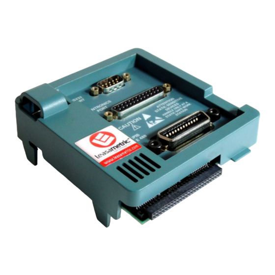
- Page 34 Each extension module also contains a GPIB, RS–232, and Centronics parallel printer interface. A ROM on the extension module contains processor instruc- tions to support the communications interfaces. Extension modules interface with the processor system through the extension module port connector. 3–2 TDS 200 Series Digital Oscilloscope Service Manual...
-
Page 35: Figure 3-1: Module-Level Block Diagram (Two Channel)
Display J131 P131 J603 DC In Backlight J604 J202 J902 Probe Comp Signal Display Control J605 Probe Comp Extension Module J601 RS232 GPIB CENTRONICS TRIG Figure 3–1: Module-level block diagram (two channel) 3–3 TDS 200 Series Digital Oscilloscope Service Manual... -
Page 36: Figure 3-2: Module-Level Block Diagram (Four Channel)
DC In J103 Backlight J102 J902 J104 Probe Comp Display Control Signal J104 Probe Comp J200 Extension Module J690 RS232 J250 GPIB J300 CENTRONICS J350 Figure 3–2: Module-level block diagram (four channel) 3–4 TDS 200 Series Digital Oscilloscope Service Manual... - Page 37 Tektronix part number connectors 011-0049-01 Dual Banana to BNC Adapter Banana plugs to BNC female Tektronix part number 103-0090-00 BNC T Adapter BNC male to dual BNC female Tektronix part number connectors 103-0030-00 4–1 TDS 200 Series Digital Oscilloscope Service Manual...
- Page 38 Channel 4 Edge Trigger Sensitivity Stable trigger — External Edge Trigger Sensitivity Stable trigger — Channels 3 and 4 are only on four channel instruments, and External Edge trigger is only on two channel instruments. 4–2 TDS 200 Series Digital Oscilloscope Service Manual...
- Page 39 1. Disconnect any probes or cables from the channel 1 and channel 2 input connectors. 2. Press the UTILITY button and select Do Self Cal to start the routine. The routine takes approximately one minute to complete. 3. Verify that Self calibration passed. 4–3 TDS 200 Series Digital Oscilloscope Service Manual...
- Page 40 5 mV/div +17.5 mV, –17.5 mV 33.3 mV to 36.7 mV 200 mV/div +700 mV, –700 mV 1.351 V to 1.449 V 2 V/div +7.00 V, –7.00 V 13.51 V to 14.49 V 4–4 TDS 200 Series Digital Oscilloscope Service Manual...
- Page 41 7. Set the leveled sine wave generator frequency to 60 MHz if you are checking a TDS 210 or to 100 MHz if you are checking a TDS 220 or TDS 224. 4–5 TDS 200 Series Digital Oscilloscope Service Manual...
- Page 42 7. Use the vertical POSITION control to center the test signal on screen. 8. Change the instrument setup using the following steps: Press menu button Select menu item Select setting HORIZONTAL Window — 4–6 TDS 200 Series Digital Oscilloscope Service Manual...
- Page 43 1. Set up the instrument using the following steps: Press menu button Select menu item Select setting SAVE/ Recall — RECALL Factory CH 1 Probe TRIGGER Mode Normal ACQUIRE Sample — MEASURE Source An unchecked channel Type Pk-Pk 4–7 TDS 200 Series Digital Oscilloscope Service Manual...
- Page 44 10. Change the instrument setup using the following steps: Press menu button Select menu item Select setting TRIGGER Slope Rising 11. Disconnect the test setup. 12. Repeat steps 1 through 11 until all input channels have been checked. 4–8 TDS 200 Series Digital Oscilloscope Service Manual...
- Page 45 750 mV. (The measured amplitude can fluctuate around 750 mV.) 7. Press SET LEVEL TO 50%. Adjust TRIGGER LEVEL as necessary and then check that triggering is stable. 4–9 TDS 200 Series Digital Oscilloscope Service Manual...
- Page 46 9. Press SET LEVEL TO 50%. Adjust TRIGGER LEVEL as necessary and then check that triggering is stable. 10. Change the instrument setup using the following steps: Press menu button Select menu item Select setting TRIGGER Slope Rising 11. Disconnect the test setup. 4–10 TDS 200 Series Digital Oscilloscope Service Manual...
-
Page 47: Table 5-1: Required Equipment
Tektronix part number 011-0049-01 connectors Termination Dual Banana to BNC Banana plugs to BNC female Tektronix part number 103-0090-00 Adapter BNC T One male and two female Tektronix part number 103-0030-00 BNC connectors 5–1 TDS 200 Series Digital Oscilloscope Service Manual... -
Page 48: Figure 5-1: Service Menu Enable Button
A Service menu selection replaces the Language menu selection, giving you access to the service routines. After adjustment is complete, disable the service menu by again holding in the internal momentary button and pressing the front panel UTILITY button. 5–2 TDS 200 Series Digital Oscilloscope Service Manual... -
Page 49: Figure 5-2: Adjustment Setups
Output Output 50 W feedthrough 50 W feedthrough terminator terminator (Table 5–2 and 5–3 list (Table 5–2 and 5–3 list proper channel) proper channel) BNC cable BNC cable Figure 5–2: Adjustment setups 5–3 TDS 200 Series Digital Oscilloscope Service Manual... - Page 50 Disconnect any probes or cables from the channel input connectors. Then, press the UTILITY button and select Do Self Cal to confirm that you are ready to proceed. 9. Disable the Service menu option. 5–4 TDS 200 Series Digital Oscilloscope Service Manual...
-
Page 51: Table 5-2: Tds 210 And Tds 220 Adjustment Steps
DC Voltage 1 20.0 V DC Voltage 1 0.0 V EXT TRIG DC Voltage 2 –5.0 V DC Voltage 2 –1.0 V DC Voltage 2 1.0 V DC Voltage 2 5.0 V 5–5 TDS 200 Series Digital Oscilloscope Service Manual... - Page 52 Sinewave Generator, 50 Ohm 50 kHz, 2.5 V Sinewave Generator, 50 Ohm 20 MHz, 2.5 V Sinewave Generator, 50 Ohm TDS 210: 60 MHz, 2.5 V TDS 220: 100 MHz, 2.5 V 5–6 TDS 200 Series Digital Oscilloscope Service Manual...
-
Page 53: Table 5-3: Tds 224 Adjustment Steps
0.4 V DC Voltage 1 0.8 V DC Voltage 1 1.2 V DC Voltage 1 1.6 V DC Voltage 1 2.0 V DC Voltage 1 20.0 V DC Voltage 1 0.0 V 5–7 TDS 200 Series Digital Oscilloscope Service Manual... - Page 54 Sinewave Generator, 50 Ohm 20 MHz, 2.5 V Sinewave Generator, 50 Ohm 100 MHz, 2.5 V Sinewave Generator, 50 Ohm 77.133 MHz, 1 V Edge, 50 Ohm 1 kHz, 0 to –800 mV 5–8 TDS 200 Series Digital Oscilloscope Service Manual...
- Page 55 Sinewave Generator, 50 Ohm 1 MHz, 2.5 V Sinewave Generator, 50 Ohm 50 kHz, 2.5 V Sinewave Generator, 50 Ohm 20 MHz, 2.5 V Sinewave Generator, 50 Ohm 100 MHz, 2.5 V 5–9 TDS 200 Series Digital Oscilloscope Service Manual...
- Page 56 Adjustment Procedures 5–10 TDS 200 Series Digital Oscilloscope Service Manual...
-
Page 57: Preparation
CAUTION. Static discharge can damage any semiconductor component in this instrument. 1. Minimize handling of static-sensitive modules. 2. Transport and store static-sensitive modules in their static protected containers or on a metal rail. Label any package that contains static-sensitive modules. 6–1 TDS 200 Series Digital Oscilloscope Service Manual... -
Page 58: Inspection And Cleaning
The front and back cases help keep dust out of the instrument and must be in place during normal operation. CAUTION. To avoid damage to the instrument or probes, do not expose it to any sprays, liquids, or solvents. 6–2 TDS 200 Series Digital Oscilloscope Service Manual... -
Page 59: Table 6-1: Internal Inspection Check List
Front and Back Cracks or deformations. Repair or replace defective hardware. Case Scratched lettering or display filter. Loose connectors or labels. Gasket and Foam Misplaced or missing pieces. Relocate or replace defective pieces. Pads 6–3 TDS 200 Series Digital Oscilloscope Service Manual... - Page 60 6. Dry all components and assemblies in an oven or drying compartment using low-temperature (52_ C to 66_ C / 125_ F to 150_ F) circulating air. Lubrication. There is no periodic lubrication required for the oscilloscope. 6–4 TDS 200 Series Digital Oscilloscope Service Manual...
-
Page 61: Removal And Installation Procedures
6–6 for a list of tools needed to remove and install modules in the oscilloscope. 3. If you are disassembling the oscilloscope for cleaning, refer to the Inspection and Cleaning procedure on page 6–3 for cleaning instructions. 6–5 TDS 200 Series Digital Oscilloscope Service Manual... - Page 62 List of Modules The Mechanical Parts List chapter provides a list of all replaceable modules. Any electrical or mechanical module, assembly, or part listed in the parts list is referred to as a module. 6–6 TDS 200 Series Digital Oscilloscope Service Manual...
-
Page 63: Table 6-2: List Of Procedures
Power Line Fuse 6–20 Power Supply Module 6–21 Front Panel Knobs 6–23 Internal Assembly 6–24 Main Board Module 6–26 Display Module 6–28 Front Panel Module 6–30 Keypad 6–33 Display Shield 6–35 Front Case 6–37 6–7 TDS 200 Series Digital Oscilloscope Service Manual... -
Page 64: Figure 6-1: Removing The Rear Feet
NOTE. You may want to use a flat blade screwdriver to pry up on the foot. Use care not to mar the surface of the rear case. Rear foot (2) Figure 6–1: Removing the rear feet 6–8 TDS 200 Series Digital Oscilloscope Service Manual... -
Page 65: Figure 6-2: Installing The Rear Feet
2. Align the slots of the rear foot with the guides in the rear case as shown in Figure 6–2 and press the foot in. Rear foot Figure 6–2: Installing the rear feet 6–9 TDS 200 Series Digital Oscilloscope Service Manual... -
Page 66: Figure 6-3: Installing A Front-Case Label
2. Handling the label by its edges only, align it with the recess in the front case as shown in Figure 6–3. 3. When properly aligned, press the new label into place. Figure 6–3: Installing a front-case label 6–10 TDS 200 Series Digital Oscilloscope Service Manual... -
Page 67: Figure 6-4: Installing A New Rear-Case Label
2. Handling the label by its edges only, align it with the recess in the rear case as shown in Figure 6–4. 3. When properly aligned, press the new label into place. Rear label Figure 6–4: Installing a new rear-case label 6–11 TDS 200 Series Digital Oscilloscope Service Manual... -
Page 68: Figure 6-5: Removing The Handle
2. With the handle laying down, pry one end of the handle out of the case as shown in Figure 6–5. NOTE. Use care not to mar the surface with the screwdriver. 3. Slide the handle towards the back of the rear case. Figure 6–5: Removing the handle 6–12 TDS 200 Series Digital Oscilloscope Service Manual... -
Page 69: Figure 6-6: Installing The Handle
Reinstall the button by pressing it onto the power button shaft until it snaps into place. NOTE. Wrap the plier jaws with tape (such as electrical) to avoid marring the button surface. 6–13 TDS 200 Series Digital Oscilloscope Service Manual... -
Page 70: Rear Case
Then tighten the screw clockwise. A properly started screw will have very little resistance going in. 4. Install the handle and the power button. 6–14 TDS 200 Series Digital Oscilloscope Service Manual... -
Page 71: Figure 6-7: Removing And Installing The Rear Cover
Maintenance Retaining screw Rear case Retaining screw Retaining tab (7) Copper mesh tubing Front case Figure 6–7: Removing and installing the rear cover 6–15 TDS 200 Series Digital Oscilloscope Service Manual... -
Page 72: Figure 6-8: Removing And Installing The Front Feet
Installation. Slide the feet into the slots provided in the front case as shown in Figure 6–8. Use the installation procedures for each module removed to reassemble the instrument. Front foot (2) Front case Figure 6–8: Removing and installing the front feet 6–16 TDS 200 Series Digital Oscilloscope Service Manual... -
Page 73: Figure 6-9: Removing And Installing The Emi Clips
Installation. Slide the four EMI clips into the slots provided in the rear case as shown in Figure 6–9. Use the installation procedures for each module removed to reassemble the instrument. Figure 6–9: Removing and installing the EMI clips 6–17 TDS 200 Series Digital Oscilloscope Service Manual... -
Page 74: Figure 6-10: Removing The Flip Stand
2. With the stand folded against the rear case (in the up position), push the stand out of the rear case channels as shown in Figure 6–10. Rear case Flip stand Figure 6–10: Removing the flip stand 6–18 TDS 200 Series Digital Oscilloscope Service Manual... -
Page 75: Figure 6-11: Installing The Flip Stand
2. With the stand in the folded up position, snap the stand into place. 3. Use the installation procedures for each module removed to reassemble the instrument. Rear case Flip stand Figure 6–11: Installing the flip stand 6–19 TDS 200 Series Digital Oscilloscope Service Manual... -
Page 76: Figure 6-12: Line Fuse Location
Use the installation procedures for each module removed to reassemble the instrument. Line fuse Power supply module Front case Figure 6–12: Line fuse location 6–20 TDS 200 Series Digital Oscilloscope Service Manual... -
Page 77: Figure 6-13: Removing The Power Supply Module
Two-conductor backlight cable Seven-conductor ribbon cable Power supply module Front case Line cord ground wire Figure 6–13: Removing the power supply module 6–21 TDS 200 Series Digital Oscilloscope Service Manual... -
Page 78: Figure 6-14: Installing The Power Supply Module
4. Use the installation procedures for each module removed to reassemble the instrument. Two-conductor backlight cable Seven-conductor ribbon cable Power supply module Front case Line cord ground wire Figure 6–14: Installing the power supply module 6–22 TDS 200 Series Digital Oscilloscope Service Manual... -
Page 79: Front Panel Knobs
Install front panel knobs by aligning the keyed knob with the shaft and pressing the knob onto the shaft. NOTE. Wrap the plier jaws with tape (such as electrical) to avoid marring the knob surface. 6–23 TDS 200 Series Digital Oscilloscope Service Manual... -
Page 80: Figure 6-15: Removing And Installing The Internal Assembly
NOTE. The switch keypad will most likely remain inside the front case. It does not need to be removed with the internal assembly. Internal assembly Keypad Conductive foam pad Front case Figure 6–15: Removing and installing the internal assembly 6–24 TDS 200 Series Digital Oscilloscope Service Manual... -
Page 81: Figure 6-16: Installing The Copper Mesh Grounding Tube
Mechanical Parts List for your serial number (see page 10–8). 3. Use the installation procedures for each module removed to reassemble the instrument. Front case Copper mesh tubing Figure 6–16: Installing the copper mesh grounding tube 6–25 TDS 200 Series Digital Oscilloscope Service Manual... -
Page 82: Main Board Module
3. From the bottom of the internal chassis, slightly bend the two securing tabs and tilt the board down until it clears the tabs. Refer to Figure 6–17. 4. Pull the board out of the front slots of the internal chassis (near the BNC connectors). 6–26 TDS 200 Series Digital Oscilloscope Service Manual... -
Page 83: Figure 6-17: Main Board Removal
The ribbon cable at J202 or J102 from the display module. 4. Place the entire internal assembly (housing all of the boards and the display screen) into the front case as shown in Figure 6–16. 6–27 TDS 200 Series Digital Oscilloscope Service Manual... -
Page 84: Figure 6-18: Main Board Installation
4. Slightly bend the two securing tabs on the left side of the display module and lift the left side up until it clears the tabs. Then slide the display to the left until the right-side tabs are disengaged. Refer to Figure 6–19. 6–28 TDS 200 Series Digital Oscilloscope Service Manual... -
Page 85: Figure 6-19: Removing The Display Module
Refer to Figure 6–20. 5. Reconnect the display module ribbon cable at J202 or J102 on the main board by pushing the cable straight down into the connector. Refer to Figure 6–17. 6–29 TDS 200 Series Digital Oscilloscope Service Manual... -
Page 86: Figure 6-20: Installing The Display Module
1. Remove the entire internal assembly from the front case using the procedure on page 6–24. 2. Disconnect the front panel ribbon cable at J200 on the main board. Refer to Figure 6–17. 6–30 TDS 200 Series Digital Oscilloscope Service Manual... -
Page 87: Figure 6-21: Removing The Front Panel Module
3. Disengage the two securing tabs at the bottom of the board and slide the board down and out of the internal chassis. Refer to Figure 6–21 Internal chassis Front panel module Figure 6–21: Removing the front panel module 6–31 TDS 200 Series Digital Oscilloscope Service Manual... -
Page 88: Figure 6-22: Installing The Front Panel Module
5. Use the installation procedures for each module removed to reassemble the instrument. Internal chassis Ribbon cable to J202 on main board Front panel module Figure 6–22: Installing the front panel module 6–32 TDS 200 Series Digital Oscilloscope Service Manual... -
Page 89: Figure 6-23: Removing And Installing The Keypad
CAUTION. Keep the electrical contacts on the back of the keypad clean. Skin oils and dust will inhibit good electrical contact. Keypad Guide post Conductive foam pad Front case Figure 6–23: Removing and installing the keypad 6–33 TDS 200 Series Digital Oscilloscope Service Manual... - Page 90 2. Check that all buttons are properly seated into place before proceeding. 3. Place the entire internal assembly into the front case as shown in Figure 6–16. 4. Use the installation procedures for each module removed to reassemble the instrument. 6–34 TDS 200 Series Digital Oscilloscope Service Manual...
-
Page 91: Figure 6-24: Removing The Display Shield
NOTE. You may have to cut through the display shield gasket to remove the shield. Carefully remove any remaining gasket and adhesive from the LCD display module. Display shield Internal chassis Front case Figure 6–24: Removing the display shield 6–35 TDS 200 Series Digital Oscilloscope Service Manual... -
Page 92: Figure 6-25: Installing The Display Shield
Align display shield with Displa guide posts on the inside of shield the front case. Guide post Front case Conductive foam pad (TDS 210 and TDS 220) Figure 6–25: Installing the display shield 6–36 TDS 200 Series Digital Oscilloscope Service Manual... -
Page 93: Front Case
4. Use the installation procedures for each module removed to reassemble the instrument. 5. If installing a new front case, place a new front-panel label onto the case as described on page 6–10. 6–37 TDS 200 Series Digital Oscilloscope Service Manual... -
Page 94: Troubleshooting
You may need the the following tools and equipment to troubleshoot the Equipment instrument. Tools and equipment Example Oscilloscope with 1X/10X and 100X probes Tektronix TDS 200- or TDS 300-series with standard accessory 1X/10X probe and optional 100X probe Tektronix TX-series digital multimeter 6–38 TDS 200 Series Digital Oscilloscope Service Manual... - Page 95 (page 6–40). Does Go to Troubleshooting backlight Backlight (page 6–41). come on? Instrument should be functioning. Try the Other Troubleshooting procedures (page 6–46) and the Front-Panel Troubleshooting (page 6–43) if other problems exist. 6–39 TDS 200 Series Digital Oscilloscope Service Manual...
- Page 96 5. Turn off the instrument and disconnect the cable at connector J131 on the main board module. 6. Turn on the instrument and check the voltages at the loose end of the cable disconnected from J131, checking for the same voltages as in step 2. 6–40 TDS 200 Series Digital Oscilloscope Service Manual...
-
Page 97: Figure 6-26: Measuring The Backlight Voltage
Figure 6–26: Measuring the backlight voltage 4. If the 1270 V signal is present, the backlight is probably defective. pk-pk Replace the display. If the signal is not present proceed with step 5. 6–41 TDS 200 Series Digital Oscilloscope Service Manual... - Page 98 = 5 V, low = 0 V 4. If all the signals are present, the display module is probably defective. Replace it. If all or some of the signals are missing, continue with step 5. 6–42 TDS 200 Series Digital Oscilloscope Service Manual...
- Page 99 Do Self Cal Performs a self calibration Error Log Displays a list of any errors logged This list is useful when contacting a Tektronix Service Center for help troubleshooting problems Service Displays the service menus for adjustment procedures and diagnostics 3.
- Page 100 Use the procedure below to isolate the problem: 8. Replace the switch keypad and then retest the buttons. If the problem persists, proceed to step 9. 6–44 TDS 200 Series Digital Oscilloscope Service Manual...
- Page 101 13. Turn on the instrument and check connector J603 or J103 for the same signals as in step 9. 14. If some or all of the signals are missing, the main board is probably defective. Replace it. 6–45 TDS 200 Series Digital Oscilloscope Service Manual...
-
Page 102: Table 6-3: List Of Error Codes
Do Self Cal Performs a self calibration Error Log Displays a list of any errors logged This list is useful when contacting a Tektronix Service Center for help troubleshooting problems Service Displays the service menus for adjustment procedures and diagnostics Table 6–3: List of error codes... - Page 103 2. Press the UTILITY button and select Service from the menu selection. 3. Select Service Diag. from the menu selection. 4. Select Clear Error Log to clear the error log of past failures. 6–47 TDS 200 Series Digital Oscilloscope Service Manual...
-
Page 104: Repackaging Instructions
Use a corrugated cardboard shipping carton having a test strength of at least 275 pounds (125 kg) and with an inside dimension at least six inches (15.25 cm) greater than the instrument dimensions. If the instrument is being shipped to a Tektronix Service Center, enclose the following information: H The owner’s address... -
Page 105: Options
Options There are no options available for the TDS 200-Series Digital Real-Time Oscilloscopes. For a list of available accessories, refer to chapter Mechanical Parts List. 7–1 TDS 200 Series Digital Oscilloscope Service Manual... - Page 106 Options 7–2 TDS 200 Series Digital Oscilloscope Service Manual...
-
Page 107: Electrical Parts List
Electrical Parts List Refer to the Mechanical Parts List chapter for a complete listing and description of replaceable parts for the TDS 200-Series Digital Real-Time Oscilloscope. 8–1 TDS 200 Series Digital Oscilloscope Service Manual... - Page 108 Electrical Parts List 8–2 TDS 200 Series Digital Oscilloscope Service Manual...
-
Page 109: Diagrams
Diagrams See Figure 3–1 on page 3–3 or Figure 3–2 on page 3–4 for a block/interconnect diagram of your oscilloscope. There are no additional diagrams in this chapter. 9–1 TDS 200 Series Digital Oscilloscope Service Manual... - Page 110 Diagrams 9–2 TDS 200 Series Digital Oscilloscope Service Manual...
-
Page 111: Replaceable Parts
Digital Real-Time Oscilloscope. Use this list to identify and order replacement parts. Parts Ordering Information Replacement parts are available through your local Tektronix field office or representative. Changes to Tektronix products are sometimes made to accommodate improved components as they become available and to give you the benefit of the latest improvements. -
Page 112: Using The Replaceable Parts List
Items in this section are referenced by figure and index numbers to the exploded view illustrations that follow. Tektronix Part Number Use this part number when ordering replacement parts from Tektronix. 3 and 4 Serial Number Column three indicates the serial number at which the part was first effective. Column four indicates the serial number at which the part was discontinued. -
Page 113: Table 10-2: Manufacturers Cross Index
C/O TJBO LIAISON BEAVERTON, OR 97077 M/S 78–210 TK2647 INSTRUMENT SPECIALTIES CO INC. C/O TEMCO NW HILLSBORO, OR 97123 1336 SE 51ST STREET TK6181 IMC PLASTICS INC 19400 SW TETON AVE TUALATIN, OR 97062 10–3 TDS 200 Series Digital Oscilloscope Service Manual... -
Page 114: Table 10-3: Replaceable Parts List
14310 SW422KA0000F03 C020100 –24VDC 15MA,450 VRMS 6MA 60KHZ,85–275VAC,TDS220 119–6025–00 POWER SUPPLY:CUSTOM,12W,5VDC 1.25A,–5VDC 0.7A, 14310 SW422KA0000F03 –24VDC 15MA,450 VRMS 6MA 60KHZ,85–275VAC,TDS224 10-1-10 441–2082–00 CHASSIS ASSY:CKT BD & LCD SUPPORT, MACROBLEND TK1163 441–2082–00 DP4–1368 10–4 TDS 200 Series Digital Oscilloscope Service Manual... - Page 115 CIRCUIT BD ASSY:MAIN,TESTED,TDS220 80009 671–5088–04 C030000 671–4514–01 B010100 B020701 CIRCUIT BD ASSY:MAIN BOARD,TESTED,TDS224 80009 671–4514–01 671–4514–02 B020702 B021579 CIRCUIT BD ASSY:MAIN BOARD,TESTED,TDS224 80009 671–4514–02 671–4514–03 B021580 CIRCUIT BD ASSY:MAIN BOARD,TESTED,TDS224 80009 671–4514–03 10–5 TDS 200 Series Digital Oscilloscope Service Manual...
- Page 116 0KB05 334–9884–00 POLY,W/ADHESIVE 10-1-21 202–0346–00 B010100 B089999 CASE,FRONT:ABS,BAYBLEND,FR110,TDS210 TK1163 202–0346–00 C010100 C019999 202–0346–01 B090100 CASE,FRONT:ABS,BAYBLEND,FR110,TDS210 TK1163 202–0346–01 C020100 202–0346–00 B010100 B059999 CASE,FRONT:ABS,BAYBLEND,FR110,TDS220 TK1163 202–0346–00 C010100 C019999 202–0346–01 B060100 CASE,FRONT:ABS,BAYBLEND,FR110,TDS220 TK1163 202–0346–01 C020100 10–6 TDS 200 Series Digital Oscilloscope Service Manual...
- Page 117 PCB,0.5 X 0.335 WIDE CONTACT,W/0.230 H X 0.5,3 PRONGED TAB,TDS220 131–6173–01 CONTACT,ESD:ESD CLIP,0.005 C17200 BECU,ACCOM 0.062 TK1326 131–6173–00 PCB,0.5 X 0.335 WIDE CONTACT,W/0.230 H X 0.5,3 PRONGED TAB,TDS224 119–5585–00 B010100 B012275 LAMP:CCFT,REPLACEMENT FOR LCD W/LEADS TK2569 LM0F2964 SHOWN 10–7 TDS 200 Series Digital Oscilloscope Service Manual...
-
Page 118: Figure 10-1: Exploded Diagram
Replaceable Parts Figure 10–1: Exploded diagram 10–8 TDS 200 Series Digital Oscilloscope Service Manual... -
Page 119: Table 10-4: Replaceable Standard Accessories
Description of accessory Tektronix part number or nomenclature Soft case AC220 Transit case* HCTDS32 Measurement Extension Module TDS2MM Communications Extension Module TDS2CM Rackmount Kit RM200 Requires the soft case which fits inside. 10–9 TDS 200 Series Digital Oscilloscope Service Manual... - Page 120 Replacement extension module instructions English 071-0409-XX French 071-0483-XX German 071-0485-XX Italian 071-0484-XX Spanish 071-0482-XX Portuguese 071-0486-XX Japanese 071-0488-XX Korean 071-0491-XX Simplified Chinese 071-0489-XX Traditional Chinese 071-0490-XX Russian 071-0487-XX Replacement programmer manual 071-0493-XX 10–10 TDS 200 Series Digital Oscilloscope Service Manual...
Need help?
Do you have a question about the TDS 200 Series and is the answer not in the manual?
Questions and answers