Advertisement
Quick Links
J
Save This Manual
For Future Reference
Sears
owners
manual
MODEL NO,
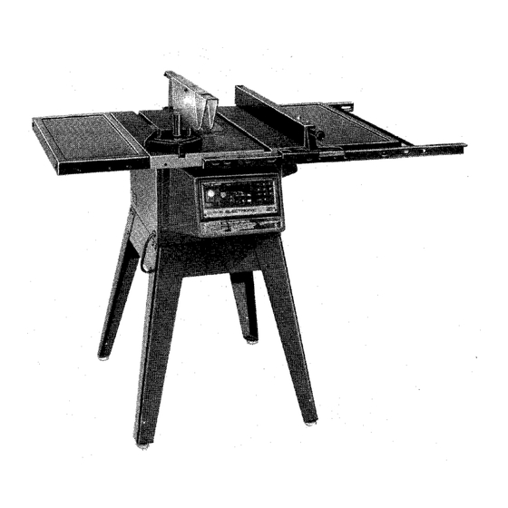
113.290060
SAW WITH
MOTOR,
LEGS AND
TWO TABLE
EXTENSIONS
Serial
Number
Model and seria
numbers may be found
at the left-hand
side
of the base
You should record both
model and serial number
ira
safe place for future
use.
CAUTION:
Read
GENERAL
and
ADDITIONAL
SAFETY
INSTRUCTIONS
carefully
CRRFTSMRN1
ELECTRONIC
IO-INCH
TABLE SA W
• assembly
• operating
• repair
parts
Sold by SEARS,
ROEBUCK
AND
CO.,
Chicago,
IL. 60684
U.S.A.
Part No. 62850
Printed in U.S.A.
Advertisement

Related Manuals for Craftsman 113.290060


Summary of Contents for Craftsman 113.290060
- Page 1 Save This Manual For Future Reference Sears owners manual MODEL NO, 113.290060 SAW WITH MOTOR, LEGS AND TWO TABLE EXTENSIONS Serial Number Model and seria numbers may be found at the left-hand side of the base You should record both CRRFTSMRN1 model and serial number safe place for future...
- Page 2 FULL ONE YEAR WARRANTYON CRAFTSMAN TABLE SAW If within one year from the date of purchase, this Craftsman Table Saw falls due to a defect in material workmanship, Sears will repair it, free of charge. WARRANTY SERVICE AVAILABLE SIMPLY CONTACTING...
- Page 3 ADDITIONAL SAFETY INSTRUCTIONS FOR TABLE SAWS WARNING: FOR YOUR OWN SAFETY, DO NOT B. Wear safety goggles that comply with ANS! OPERATE YOUR SAW UNTIL IT IS COMPLETELY Z87.1, and a face shield or dust mask if ASSEMBLED AND INSTALLED ACCORDING operation is dusty.
- Page 4 N. Shut "OFF" disconnect designed.. For greatest safety and efficiency when r_ppmg, use the maximum diameter blade oower cord wnen removmg the table insert for which the saw is designed, since under these changing cutting tool. removing conditions the spreader is nearest the blade.
- Page 5 MOTOR SPECIFICATIONS AND ELECTRICAL REQUIREMENTS conductor has a green lug and is attached to the tool This saw is designed to use a 3450 RPM motor only. housing at one end and to the ground prong in the Do not use any motor that runs faster than 3450 attachment plug at the other end.
- Page 6 UNPACKING AND CHECKING CONTENTS TOOLS NEEDED COMBINATION SQUARE MUST BE TRUE. STRAIGHT EDGE OF BOARD 3/4" THICK. THIS EDGE MUST Medium Screwdriver DRAW LIGHT LINE BE PERFECTLY STRAIGHT. Small Screwdriver #2 Phillips Type Screwdriver =_'i ' iilr"_ Pliers Wrenches _,..._, ,.', : [ 3/8 in.
- Page 7 Item Part Name Qty. Loose Parts Bag No. 62745 ..... (Containing the Following Items): AA Bracket, Corner Support ....BB Bracket, Corner Stiffener ....Loose Parts Bag No. 62837 ..... Loose Parts Bag No. 62837 (Containing the Following Items): CC Screw, Truss Hd. 1/4-20 x 1 .... DD Lockwasher, External 1/4 ....
- Page 8 ASSEMBLY ASSEMBLING STEEL LEGS NOTE: Steel Legs furnished with Model 113.290060. ASSEMBLE SCREWS From among the loose parts, find the following THROUGH HOLES MARKED "X" Hardware: 24 Truss Head Screws, 1/4-20 x 5/8 in. long (top SIDE STIFFENER of screw is rounded) 24 Lockwashers, 1/4 in.
- Page 9 2. Placesawon legssothatholesin bottonofsaw 7/16 DIA. HOLES line up with holesin top of legs. 11-1/4 3. Installscrews,washers, I ockwashers andnuts asshown. If you mount the saw on any other bench, make sure 10-1/4 that there is an opening in the top of the bench the same size as the opening in the bottom of the saw so OPENING that the sawdust can drop through.
- Page 10 MOUNTING THE MOTOR THESE TWO CARRIAGE BOLT LOCKWASHER 1. From among the loose parts, find the following EDGES EVEN 5116-18 X 314 IN. 5/16 hardware: 2 Hex Head Screws 5/16-18 x 5/8 in. long ./" 4 Carriage Bolts, 5/16-18 x 3/4 in. long 5/16-18 4 Hex Nuts.
- Page 11 IMPORTANT: FOR STORE DISPLAY THE SAW MOTOR MUST NOT BE CONNECTED. DO NOT PERFORM STEPS 1 THROUGH MOTOR CONNECTIONS TERMINA L GREEN WARNING: FOR YOUR OWN SAFETY, NEVER CONNECT PLUG TO POWER SOURCE OUTLET UNTIL ALL ASSEMBLY STEPS ARE COMPLETED INTERNAL.
- Page 12 Lay REAR FENCE GUIDE BAR on table to act as a straightedge. If outer edge of extension is higher or lower than table surface: A Slightly loosen nut holding the corner support bracket to extension using 7/16 in. wrench. 53.Move end of extension up or down until outer edge is even with table surface.., check with...
- Page 13 9. Holdrodwithonehandandwitha 1/2in. wrench ;)liers start screwing on ONE of the nuts on y A TURN OR TWO ..screwon other nut the same way. 10. Using TWO 1/2 in. wrenches or pliers tighten both of the nuts. 11. Slide the bars so that screws are in the MIDDLE of the slotted holes.
- Page 14 8THICKNESSES OF PAPER 22.Carefullymovefenceagainstblade. 23.Movefront bar until ,'0" mark on ripscale approximately inline with indicator. Move FRONT upwards until fence approximately 1/32 in. above table.., tighten screw at left end of bar. NOTE: Fold a piece of newspaper making thicknesses and place between rip fence and table to act as a spacer.
- Page 15 For very close adjustments, grasp the guide bar with both hands and move the fence with your thumbs. With fence on saw but NOT LOCKED move the REAR END.of the fence slightly tothe right or left... when you release it, the fence should "spring" back to its original position.
- Page 16 HEX SCREWS 3. The rip fence must be PARALLEL with the FENCE HEAD sawblade and miter Gaugegrooves. . . Move fence until it is alongsideof groove.DONOT LOCKIT. It shouldbeparallel t o groove.If it is not: A Loosenthetwo "Hex HeadScrews." 53. Holdfencehea(_ t ightlyagainst b ar.., move endof fenceso thatit is parallel w ithgroove, C.
- Page 17 NOTE: All six screws can be reached through back of saw. Use a 9/16-in. wrench. To reach left-hand front trunnion screws, tilt blade to approximately 25 ° . After loosening screws reposition blade at 90 ° . To make this adjustment: a.
- Page 18 INSTALLING BLADE GUARD 1. From among the loose parts, find 2 Hex Head Screws, 1/4-20 x 5/8 in. long 1 Hex Head Screw, 5/16-18x 5/8 in. long 2 Hex Head Screws, 5/16-18 x 1 in. long 5/16-18 X 2 Hex Nuts, 1/4-20 5/8 IN.
- Page 19 8. Raise Blade Guard .lift up both ANTIKICKBACK PAWLS... insertoneof the SETSCREW WRENCHES i n the notches to hold the pawlsout of the way. 9. Lay blade of square or other straightedge alongsideof blade. 10.LoosenHexHead Screwin GUARD SUPPORT and movespreaderso that it touchesbladeof square.., tightenscrew.
- Page 20 INSTALLING BELT GUARD SUPPORT 1. Screws furnished with guard "self threading".., screw them into holes in BELT GUARD SUPPORT BRACKET. then remove them. 2. Position BELT GUARD SUPPORT BRACKET and BELT GUARD SUPPORT as shown and install the screws., make sure motor shaft is in CENTER of hole in SUPPORT.
- Page 21 3. Loosen two motor base clamp screws.., push motor in as far as it will go. 4. a. Plug in saw, turn MASTER switch "ON". b. Press key. c. Press and hold key to lower blade even BASE j with table top. EDGE OF WASHER EVEN WITH d.
- Page 22 MITER GAUGE LOCK KNOB NOTE: The slots for the Stop Pin and the angle graduations are manufactured to close tolerances which provide accuracy most woodworking STOP projects. In cases where greater accuracy required, it is recommended that a trial cut be made and checked before cutting the actual.workp_ece.
- Page 23 LOCATION FUNCTION OF MECHANICAL CONTROLS 10. SAWBLADE 11. EXACT-I-CUT 8. BLADE GUARD MITER GAUGE 9. TABLE LOCK HANDLE INSERT ANTIKICKBACK PAWLS 6. RIP FENCE 7. MITER GAUGEX_ HOLES FOR WOODEN FACING RIP FENCE LOCK HANI ELECTRONIC CONTR! CAUTION: Before turning switch on, make sure the blade guard is correctly installed and operating properly.
- Page 24 2. SAWMOTOR SWITCH: calibrating. flashing"['" on y Thisswitchis usedto turnthesawmotoronand displayed when the saw requires calibrating off. due to either a power interruption or the saw has been unplugged. NOTE: Pushing off either the Saw Motor Switch or the Master Switch will shut off power to the 4.
- Page 25 D.The _L_ key,whenpressed, w ill starta Attach it to the fence with three Round Head #10 Wood Screws 2 in. long. To remove the facing, programmed motion. loosen the screws, slide the facing backward It becomes inactivewhilethe sawmotor is "ON". and pull the screws through the round holes.
- Page 26 NEVER OPERATE THE SAW WITHOUT 8. BLADEGUARD must always be in place and PROPER INSERT IN PLACE. USE THE SAW working properly for all thru-sawing cuts. That BLADE INSERT WHEN SAWING ... USE THE is, all cuts where the blade cuts completely COMBINATION DADO-MOLDING INSERT...
- Page 27 A. Check disc.., if it is above table surface, NOTE:When using the Dado or Molding Head. it is not necessary to install the loose collar. Refer to place a piece of hardwood on top of itand tap it down. instruction sheet packed with dado or molding...
- Page 28 USING THE MITER GAUGE 6, Do not stand directly in front of the blade in case FOR CROSSCUTTING. MITER CUTTING. BEVEL of a THROWBACK (Small cut-off piece caught CUTTING. COMPOUND MITER CUTTING. by the back of the blade and thrown toward the DADOING when RABBETTING...
- Page 29 CALIBRATING THE SAW FOR ELECTRONIC OPERATIONS Whenever the saw has been unplugged or there has Calibration Procedure Using 10" Diameter Sawblade. been an interruption in power, it will be necessaryto calibrate the "zero" points for the elevation 1. Plug in the saw and insert yellow key into bevel operations.
- Page 30 SHUT DOWN PROCEDURE TO RETAIN CALIBRATION By following the procedure below when the work session is over, recalibration is done by simply pressing the _ key after the saw is plugged in and the MASTER switch is turned "ON". 1. Press key.
- Page 31 CROSSCUTTING CROSSCUTTING is cutting wood across the grain, at 90 ° , or square with both the edge and the flat side of the wood. This is done with miter gauge set at "0". graduations miter gauge provide SANDPAPI accuracy for average woodworking.
- Page 32 When cutting long workpieces, _nvert AUXILIARY FENCE/WORK SUPPORT and position it on top of the guide bars to support the workpiece as near to the end as possible. If this does not adequately support the workpJece, you can make a simple support by clamping a piece...
- Page 33 MITER CUTTING MITER CUTTING is cutting wood at an angle other than g0 0 with the edge of the wood. Follow the same procedure as you would for crosscutting. Adjust the miter gauge to the desired angle, and lock it. TABLE The miter gauge may be used in either of the...
- Page 34 BEVEL CROSSCUTTING BEVEL CROSSCUTTING same crosscutting except that the wood is cut at an angle other than 90 ° with the flat side of the wood Adjus! the blade to the desired angle. WORKPIECE Set blade elevation to clear top of workpiece by 1/8".
- Page 35 USING THE RIP FENCE RIPPING, BEVEL RIPPING, PLOUGHING, 5. Have blade extend approximately 1/8 in. above MOLDING, RESAWING RABBETING top of workpiece. Additional blade exposure would increase the hazard potential. performed using the RIP FENCE together with the AUXILIARY FENCE/WORK SUPPORT, PUSH 6.
- Page 36 When "Wl DTH OF RIP" is 6 in. and WIDER use your RIGHT Hand to feed the workpiece until it is clear of the table. LEFT hand ONLY guide OR MORE workpiece., do not-FEED the workpiece with the left hand When "WlDTE OF RIP"...
- Page 37 Feedthe workpiece by handalongthe AUXILIARY FENCE untilthe endis approx.1 in. pastthe front edgeof the table.Continue tofeedusingthe PUSH BLOCK. Holdtheworkpiece i_ ,_osition andinstall t hePUSH BLOCK by sliding it on top of the AUXILIARY FENCE/WORK SUPPORT (ThisMayRaise Guard). Narrow stripsthickerthantheAuxiliaryFence/Work Supportmayenterthe guardandstrike the baffle. CAREFULLY raiseguardonly enoughto clearthe workpiece.
- Page 38 PLOUGHING MOLDING PLOUGHING s grooving with grain the long way of the workpiece, using the fence. Use proper holddowns and feed devices. PLOUGHING MOLDING is shaping the workpiece with the grain the long way of the workpiece, using the fence. Use proper holddowns and feed devices.
- Page 39 RABBETING RABBETING is known as cutting out a section of the corner of a piece of material, across an end or along an edge. To make a RABBET requires cuts which do not go all the way through the material. Therefore the blade guard must be removed.
- Page 40 USING FEATHERBOARDS (sawblade, dado head, molding head. etc.) with a pushstick, as in ripping. Add 8 inch high flat facing board to the fence, the Before starting the operation (switch 'OFF' and full length of the fence. cutter below table surface): featherboards "thru-sawing"...
- Page 41 Frequently blow out any dust that may accumulate inside the saw cabinet and the motor. Frequently clean you cutting tools with Craftsman Gum and Pitch Remover. A coat of automobile-type wax applied to the table wil! help to keep the...
- Page 42 TROUBLE SHOOTING WARNING: FOR YOUR SAFETY, TURN SWITCH "OFF" AND ALWAYS REMOVE PLUG FROM POWER SOURCE OUTLET BEFORE TROUBLE SHOOTING. TROUBLE SHOOTING -- GENERAL REMEDY TROUBLE PROBABLE CAUSE 1. Discard Blade and use a different blade. Excessive vibration. 1. Blade out of balance.
- Page 43 TROUBLE SHOOTING -- SAW MOTOR (Continued) TROUBLE PROBABLE CAUSE REMEDY Motor starts slowly Low voltage will not 1. Request voltage check from the power company. or fails to come trip relay. to full speed. Windings burned 2. Have motor repaired or replaced.
- Page 44 1. Turn master switch "OFF" then "ON". respond correctly still not right unplug saw from power supply to keys. momentarily. Recalibrate saw. p. 29. If you require further help on operating your new Craftsman Electronic Table Saw call 800-325-1184. In Missouri call 314-595-2500.
- Page 45 © CALIBRATION GAUGE Use to set calibration point in elevation for cutting tools 10" or smaller, such as DADO or MOLDING HEAD. THIS LINE EVEN WITH TABLE DIRECTIONS 1, Unplug saw; remove cutting tool. 2. Assemble cutting tool instructions with cutting tool tighten...
- Page 46 PARTS LIST FOR CRAFTSMAN 10 INCH TABLE MODEL NO. 113.290060 1> 29 30 25 24 46 24 62 _...
- Page 47 FIGURE 1 PARTS LIST FOR CRAFTSMAN 10 INCH TABLE MODEL NO. 113.290060 Always Order by Part Number - not by Key Number Part Part Description Description 62825 Housing, Support 62579 ,Guard Assembly (See Fig. 5) 75084 Screw, Pan Hd. Plastite No. 6 x 2-1/4 STD522506 Screw, Hex Hd.
- Page 48 PARTS LIST FOR CRAFTSMAN 10 INCH TABLE MODEL NO. 113.290600 & 113.290650 1i 1314 J/15 €o 40 39 36 37 38 Figure 2...
- Page 49 PARTS LIST FOR CRAFTSMAN 10 INCH TABLE MODEL NO. 113.290600 & 113.290650 Part Part Description Description 62828 Shaft, Elevation 62587 Support, Spreader 62819 Bracket, Elevation 60204 Screw, thumb 5/16-18 x 1 STD551210 *Lockwasher, External No. 10 STD571812 *Pin, Roll 3/!6 x 1-1/4 STD601103 *Screw, Pan Cross Type "T"...
- Page 50 PARTS LIST FOR CRAFTSMAN 10 INCH TABLE SAW MODEL NO. 113.290060 FIGURE 3 - 62773 FENCE ASSEMBLY Part Description 62773 Fence Assembly, 62693 Plug, Button 62692 Knob (Includes Key No. 1) STD551031 *Washer, 21/64 I.D. 62775 Indicator, Fence 9404336 *Screw, Pan Hd. Type "T" 4-40 x 1/4...
- Page 51 PARTS LIST FOR CRAFTSMAN 10 INCH TABLE MODEL NO. 113.290060 FIGURE 4 - 62704 MITER GAUGE ASSEMBLY Part Description 62704 tGauge Assembly, Miter 62693 Plug, Button 62692 Knob, Miter Gauge (Includes Key No. 1) 60024 *Washer, Plain 21/64 x 1 x 1/16"...
- Page 52 PARTS LIST FOR CRAFTSMAN 10 INCH TABLE MODEL NO. 113.290060 FIGURE 5 - 62579 GUARD ASSEMBLY Pa rt Description 62579 Guard Assembly, 60297 Nut', Push Pin 1/4 x 1-1/2" 62391 62395 Support, Guard 62389 Guard, Saw 62390 Pin, 1/4 x 1-3/4"...
- Page 53 PARTS LIST FOR CRAFTSMAN 10 INCH TABLE MODEL 113.290060 FIGURE 6 - TABLE EXTENSION Part Description 62589 tExtension Assembly, Complete 60323 Screw, Serrated Truss Hd., 1/4-20 x 1" Extension 62590 62549 Bracket, Corner Support STD541025 *Nut, Hex 1/4-20 *Lockwasher, Ext. 1/4...
- Page 54 PARTS LIST FOR CRAFTSMAN 10 INCH TABLE MODEL NO. 113.290060 FIGURE 7 - LEGS Part Description 60314 Screw, Serrated Truss Hd. 1/4-20 x 5/8 62552 62554 Stiffener, Side STD551225 *Lockwasher, Ext. 1/4 *Nut, Hex 1/4-20 STD541025 62553 Stiffener, STD541250 *Nut, Hex 1/2-13...
- Page 55 ELECTRONIC TABLE SAW CONTROL PANEL OPERATIONS DANGER MANUAL. YOUR MANUAL CONTAINS SAFETY INSTRUCTIONS DETAILED I DO OPERATE SAW WITHOUT FIRST READING UNDERSTANDING OWNER'S I EXPLANATIONS OF KEYBOARD FUNCTIONS AND BASIC SAW OPERATIONS. RESULTDESIRED DISPLAY ACTIONREgLIIRED DECIMAL EQUIVALENT8 Plug in saw; Turn MasterSwitch "ON" Flashing .030 1.
- Page 56 Sears I 10 INCH owners ELECTRONIC TABLE SAW manual SERVICE Now that you have purchased your 10-inch electronic table saw should a need ever exist repair parts or service. s_mply contact any Sears Service Center and most Sears Roebuck and Co stores.
Need help?
Do you have a question about the 113.290060 and is the answer not in the manual?
Questions and answers