Table of Contents
Advertisement
Quick Links
Advertisement
Table of Contents

Related Manuals for VIA Technologies EPIA-SP8000E - VIA Motherboard - Mini ITX


Summary of Contents for VIA Technologies EPIA-SP8000E - VIA Motherboard - Mini ITX
- Page 1 User’s Manual EPIA-SP Version 1.12 January 30, 2012...
- Page 2 However, VIA Technologies assumes no responsibility for the use or misuse of the information in this document and for any patent infringements that may arise from the use of this document.
- Page 3 FCC-B Radio Frequency Interference Statement This equipment has been tested and found to comply with the limits for a class B digital device, pursuant to part 15 of the FCC rules. These limits are designed to provide reasonable protection against harmful interference when the equipment is operated in a commercial environment.
-
Page 4: Safety Instructions
Safety Instructions Always read the safety instructions carefully. Keep this User's Manual for future reference. Keep this equipment away from humidity. Lay this equipment on a reliable flat surface before setting it up. The openings on the enclosure are for air convection hence protects the equipment from overheating. - Page 5 ONTENTS One VIA Mini-ITX mainboard One Quick Installation Guide One ATA-133/100 IDE ribbon cable One driver and utilities CD One IO bracket...
-
Page 6: Table Of Contents
ABLE OF ONTENTS Box Contents ................i Table of Contents................ii Chapter 1 ..................1 Specifications ................1 Mainboard Specifications ............2 Mainboard Layout ..............4 Back Panel Layout ..............5 Back Panel Ports ............... 6 Slots ..................6 Onboard Connectors ..............7 Onboard Jumpers .............. - Page 7 Integrated Peripherals..............59 Super IO Device ..............61 Power Management Setup............63 Peripheral Activities..............65 IRQs Activities .................68 PNP/PCI Configurations............69 IRQ Resources.................71 PC Health Status..............72 Frequency / Voltage Control .............73 Load Fail-Safe Defaults ............76 Load Optimized Defaults ............77 Set Supervisor / User Password ..........78 Save &...
- Page 8 This page is intentionally left blank.
-
Page 9: Chapter 1
Specifications The ultra-compact and highly integrated VIA EPIA-SP uses the Mini- ITX mainboard form-factor developed by VIA Technologies, Inc. as part of the company’s open industry-wide total connectivity initiative. The mainboard enables the creation of an exciting new generation of small, ergonomic, innovative and affordable embedded systems. -
Page 10: Mainboard Specifications
Chapter 1 AINBOARD PECIFICATIONS VIA C3 / Eden EBGA Processor Chipset VIA CN400 North Bridge VIA VT8237R-series South Bridge Graphics Integrated UniChrome™ Pro AGP with MPEG-2 decoding Audio VIA VT1617A 6-channel AC'97 Codec Memory 1 x DDR 400 / 333 / 266 DIMM socket (up to 1 GB) Expansion Slot 1 x PCI slot 2 x UltraDMA 133/100 connectors, with Direct DOM Support... - Page 11 Specifications Back Panel I/O Ports 1 x PS/2 mouse port and 1 x PS/2 keyboard port 1 x RJ-45 LAN port 1 x Serial port 2 x USB 2.0 ports 1 x RCA port (SPDIF or TV out) 1 x S-Video port 1 x VGA port 3 x Audio Jacks: line-out, line-in and mic-in (Horizontal, Smart 5.1 Support)
-
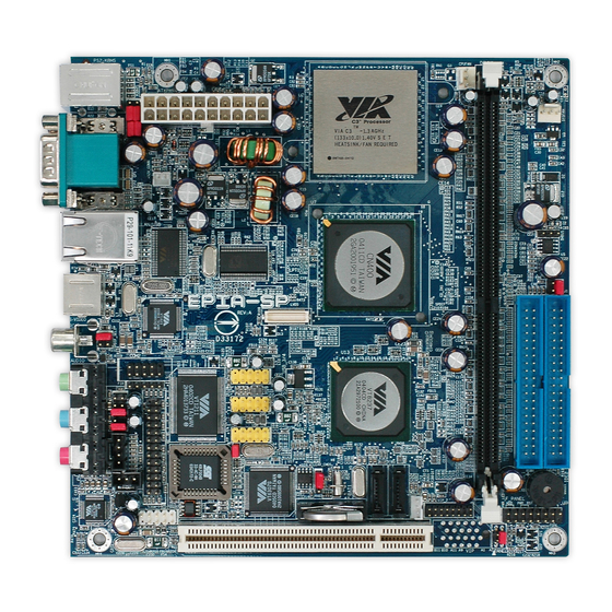
Page 12: Mainboard Layout
Chapter 1 AINBOARD AYOUT Top: Mouse Bottom: Keyboard ATXPWR CPUFAN SYSFAN KBMS C3 Processor DIMM1 Top: COM1 Bottom: VGA port +12V_PWR SMBus Top: RJ45 port Bottom: USB port S-Video port LVDS RCA Jack SPDIF_SEL1 USB 3/4 COM2 Line-Out USB 5/6 Line-In USB 7/8 Microphone... -
Page 13: Back Panel Layout
Specifications ANEL AYOUT PS/2 Mouse COM1 RJ45 RCA / SPDIF PS/2 Keyboard VGA Out S-Video Line-Out Line-In Microphone... -
Page 14: Back Panel Ports
Chapter 1 ANEL ORTS Port Description Page Audio Jacks 3 Audio ports (line-out, line-in and mic-in) 19-22 COM1 Serial port 1 PS/2 Mouse PS/2 mouse port PS/2 Keyboard PS/2 keyboard port RCA/SPDIF RCA port (SPDIF or TV out) 19-20 RJ45 RJ45 port 19-20 USB 2.0 ports... -
Page 15: Onboard Connectors
Specifications NBOARD ONNECTORS Connector Description Page +12V_CONN 12V Power connector 12-13 1394_1 IEEE 1394 connector 31-32 ATXPWR Power cable connector 17-18 CD_IN Onboard CD audio cable connector 31-32 COM 2 COM port 2 connector 31-32 CPUFAN CPU fan connector Fast Infrared Radiation connector F_AUDIO Front Audio connector 33-34... - Page 16 Chapter 1 This page is intentionally left blank.
-
Page 17: Chapter 2
HAPTER Installation This chapter provides you with information about hardware installation procedures. It is recommended to use a grounded wrist strap before handling computer components. Electrostatic discharge (ESD) can damage some components. -
Page 18: Cpu
Chapter 2 The VIA C3 E-Series Processor The VIA EPIA-SP Mini-ITX mainboard includes an embedded VIA C3 or Eden Processor. The VIA C3 Processor provides ultra-low power consumption and advanced thermal dissipation properties. The VIA C3 Processor requires heatsink and a CPU fan to provide sufficient cooling. Ensure that the CPU fan is correctly installed as shown. -
Page 19: The Via Eden Processor
Installation The VIA Eden Processor Providing ultra-low power consumption and advanced thermal dissipation properties, the VIA Eden Processor features a fanless design. The VIA Eden Processor requires only a heatsink as shown. Caution: This mainboard is not designed to support overclocking. Any attempt to operate beyond product specifications is not recommended. - Page 20 Chapter 2 CPU Fan and System Fan: CPUFAN and SYSFAN The CPUFAN (CPU fan) and SYSFAN (system fan) run on +12V and maintain system cooling. When connecting the wire to the connectors, always be aware that the red wire is the Positive and should be connected to the +12V. The black wire is Ground and should always be connected to GND.
- Page 21 Installation +12V Power Connector This 12V power connector is used to provide additional +12V power to the rest of the system. Signal +12V +12V_CONN...
-
Page 22: Memory Module Installation
Chapter 2 EMORY ODULE NSTALLATION The VIA EPIA-SP Mini-ITX mainboard provides one 184-pin DIMM slot for DDR400/333/266 SDRAM memory modules and supports the memory size up to 1GB. DDR SDRAM Module Installation Procedures Locate the DIMM sockets in the motherboard. C3 Processor DIMM1... - Page 23 Installation Unlock a DIMM socket by pressing the retaining clips outward. Align a DIMM on the socket such that the notch on the DIMM matches the break on the socket. Firmly insert the DIMM into the socket until the retaining clips snap back in place and the DIMM is properly seated.
- Page 24 Chapter 2 Available DDR SDRAM Configurations Refer to the table below for available DDR SDRAM configurations on the mainboard. Slot Module Size Total DIMM 64MB, 128MB, 256MB, 512MB, 1GB 64MB-1GB Maximum supported system memory 64MB-1GB...
-
Page 25: Connecting The Power Supply
Installation ONNECTING THE OWER UPPLY The VIA EPIA-SP Mini-ITX mainboard supports a conventional ATX power supply for the power system. Before inserting the power supply connector, always make sure that all components are installed correctly to ensure that no damage will be caused. ATX 20-Pin Power Connector To connect the ATX power supply, make sure the power plug is inserted in the proper orientation and the pins are aligned. - Page 26 Chapter 2 ATX 20 Pin Power Connector Signal Signal +3.3V +3.3V +3.3V -12V Power Supply On Power Good +5V Standby +12V...
-
Page 27: Back Panel Ports
Installation ANEL ORTS The back panel has the following ports: PS/2 Mouse COM1 RJ45 RCA / SPDIF PS/2 Keyboard VGA Out S-Video Line-Out Line-In Microphone Keyboard and Mouse The green 6-pin connector is for a PS/2 mouse. The purple connector is for a PS/2 keyboard. VGA Out The 15-pin female VGA connector can be used to connect to any analog VGA monitor. - Page 28 Chapter 2 RJ45 10/100 LAN Connector The mainboard provides a standard RJ-45 port. This port allows connection to a Local Area Network (LAN) through a network hub USB 2.0 ports 1and 2 These two 4-pin Universal Serial Bus (USB) ports are available for connecting USB 2.0 devices.
-
Page 29: Audio Port
Installation Audio Port: Line Out jack This Line Out (lime) jack connects a headphone or a speaker. In 6-channel mode, the function of this jack becomes Front Speaker Out. Line In jack This Line In (light blue) jack connects a tape player or other audio devices. In 6-channel mode, the function of this jack becomes Rear Speaker Out. - Page 30 Chapter 2 Shown below are the corresponding connections to setup the 6-channel system. Jack 2-channel 6-channel Line-out Line-out Front (Left/Right) Line-in Line-in Rear (Left/Right) Microphone Microphone Center/Sub-woofer...
-
Page 31: Connectors
Installation ONNECTORS Hard Disk Connectors: IDE1 & IDE2 The mainboard has a 32-bit Enhanced IDE and Ultra DMA 133/100 controller that provides PIO mode 0~4, Bus Master, and Ultra DMA 133/100 functions. You can connect up to four hard disk drives, CD-ROM and other devices. The primary hard drive should always be connected to IDE1 as the master drive. - Page 32 Chapter 2 If two drives are connected to a single cable, the jumper on the second drive must be set to slave mode. Refer to the drive documentation supplied by the vendor for the jumper settings. Both IDE1 and IDE2 have a 20 included.
- Page 33 Installation Serial ATA Connectors: SATA1 and SATA2 These next generation connectors support the thin Serial ATA cables for primary internal storage devices. The current Serial ATA interface allows up to 150MB/s data transfer rate, faster than the standard parallel ATA with 133 MB/s (Ultra DMA).
- Page 34 Chapter 2 Case Connector: F_PANEL The F_PANEL pin header allows you to connect the power switch, reset switch, power LED, HDD LED and the case speaker. C3 Processor F_PANEL Case Connector: F_PANEL Signal Signal +5VDUAL +5VDUAL HD_LED -PLED PW_BN RST_SW SPEAK -SLEEP_LED...
- Page 35 Installation Power Switch (PW_BN) Connect to a 2-pin power button switch. Pressing this button will turn the system power on or off. Reset Switch (RST_SW) The reset switch is used to reboot the system rather than turning the power ON/OFF. Avoid rebooting the system, if the HDD is still working. Connect the reset switch from the system case to this pin.
- Page 36 Chapter 2 Fast IrDA Infrared Module Connector: FIR This pin header is used to connect to an IrDA module. The BIOS settings must be configured to activate the IR function. Signal Description IRRX1 FIR/SIR Data Receive IRRX SIR Data Receive Ground IRTX FIR/SIR Data Transmit...
- Page 37 Installation Digital Audio Connector: S/PDIF This connector is for connecting the Sony Philips Digital Interface (S/PDIF) bracket. The S/PDIF output provides digital audio to external speakers or compressed AC3 data to an external Dolby Digital Decoder. The feature is available only with stereo system that has digital output function. Signal S/PDIF SPDIF...
- Page 38 Chapter 2 USB Pin Connectors: USB 3-4, 5-6, and 7-8 The mainboard provides 3 front USB pin header connectors, allowing up to 6 additional USB2.0 ports up to maximum throughput of 480 Mbps. Connect each 2-port USB cable into each pin headers. These ports can be used to connect high-speed USB interface peripherals such as USB HDD, digital cameras, MP3 players, printers, modem and the like.
- Page 39 Installation Wake-On LAN: WOL This connector allows you to connect a network card with the Wake-On LAN function. The connector will power up the system when a signal is received through the network card. Please note that the function of ACPI WOL may be disabled when users will unplug the power cord or turn off the power button manually.
- Page 40 Chapter 2 Serial Port: COM 2 COM2 can be used to attach additional port for serial mouse or another serial device. Signal Signal SOUT COM2 CD Audio Connector: CD_IN This connector allows you to receive stereo audio input from sound source such as a CD-ROM.
- Page 41 Installation System Management Bus Connector: SMBus The pin header allows you to connect SMBus (System Management Bus) devices. Devices communicate with an SMBus host and/or other SMBus devices using the SMBus interface Signal SMBCK SMBDT C3 Processor SMBus...
- Page 42 Chapter 2 Front Panel Audio Connector: F_AUDIO This is an interface for the VIA front panel audio cable that allow convenient connection and control of audio devices. By default, the pins labeled LINE_OUT_R/NEXT_R and the pins LINE_OUT_L/NEXT_L are shorted with jumper caps.
- Page 43 Installation Video Interface Port Pin Connector: VIP_2 This pin header allows you to use the capture function inside the North Bridge. Signal Signal CAPD0 CAPD7 CAPD4 CAPD6 CAPD5 GFPHS CAPD2 CAPD1 CAPD3 GFPVS CAPCLK SMBDT SMBCK C3 Processor VIP_2...
- Page 44 Chapter 2 LVDS Connector: This connector works as the interface to multi display devices. An additional daughter card is required for a certain display support. Daughter cards for LVDS and DVI are currently available respectively. C3 Processor LVDS...
- Page 45 Installation LVDS Connector Signal Signal GFPCLK GFPD12 GFPD15 GFPD11 GFPD14 GFPD1 GFPD3 GFPD6 GFPD16 GFPD7 GFPD17 GFPD0 GFPD2 GFPD4 GFPD18 GFPD8 GFPD19 GFPD5 GFPD21 GFPD9 GFPD20 GFPD10 GFPD22 GFPD13 GFPD23 ENPVDD GFPVS ENPVEE GFPHS FPBKLP GFPDE PWRGD_SB TVBSCK_R +3.3V TVBSDA_R Note: ENPVDD: Enable Panel VDD power ENVEE: Enable panel VEE power...
-
Page 46: Jumpers
Chapter 2 UMPERS The mainboard provides jumpers for setting some mainboard functions. This section will explain how to change the settings of the mainboard functions using the jumpers. C3 Processor KBMS RCA/SPDIF CLEAR_CMOS... - Page 47 Installation Clear CMOS: CLEAR_CMOS This jumper allows you to clear the Real Time Clock (RTC) RAM in CMOS. You can clear the CMOS memory of date, time and system setup parameters by erasing the CMOS RTC RAM data. The onboard button cell battery powers the RAM data in CMOS that include system setup information such as 1-2: Normal (Default)
- Page 48 Chapter 2 PS2 Header: KBMS (Keyboard Mouse) When the pin header is not in use, please short pin 3&5, pin 4&6, pin 7&9 and pin 8&10. Signal Signal KB_CLK KB_DATA EXT_KBCLK EXT_KBDATA MS_CLK MS_DATA EXT_MSCLK EXT_MSDATA KBMS RCA Video or S/PDIF Select: RCA / SPDIF Using this selector, users can select either RCA Video or S/PDIF as the enabled function on the dual-purpose port.
-
Page 49: Slots
Installation LOTS Peripheral Component Interconnect: PCI The PCI slot allows you to insert PCI expansion card. When adding or removing expansion card, unplug first the power supply. Read the documentation for the expansion card if any changes to the system are necessary. - Page 50 Chapter 2 PCI Interrupt Request Routing The IRQ (interrupt request line) are hardware lines over which devices can send interrupt signals to the microprocessor. The “PCI & LAN” IRQ pins are typically connected to the PCI bus INT A# ~ INT D# pins as follows: Order 1 Order 2 Order 3...
-
Page 51: Chapter 3
HAPTER BIOS Setup This chapter gives a detailed explanation of the BIOS setup functions. -
Page 52: Entering Setup
Chapter 3 NTERING ETUP Power on the computer and press <Delete> during the beginning of the boot sequence to enter the BIOS setup menu. If you missed the BIOS setup entry point, you may restart the system and try again. -
Page 53: Control Keys
BIOS Setup ONTROL Keys Description Up Arrow Move to the previous item Down Arrow Move to the next item Left Arrow Move to the item in the left side Right Arrow Move to the item in the right side Enter Select the item Escape Jumps to the Exit menu or returns to the main menu... -
Page 54: Navigating The Bios Menus
Chapter 3 BIOS M AVIGATING THE ENUS The main menu displays all the BIOS setup categories. Use the control keys Up/Down arrow keys to select any item/sub-menu. Description of the selected/highlighted category is displayed at the bottom of the screen. An arrow symbol next to a field indicates that a sub-menu is available (see figure below). -
Page 55: Getting Help
BIOS Setup ETTING The BIOS setup program provides a “General Help” screen. You can display this screen from any menu/sub-menu by pressing <F1>. The help screen displays the keys for using and navigating the BIOS setup. Press <Esc> to exit the help screen. -
Page 56: Main Menu
Chapter 3 Phoenix - AwardBIOS CMOS Setup Utility Standard CMOS Features Frequency / Voltage Control Advanced BIOS Features Load Fail-Safe Defaults Advanced Chipset Features Load Optimized Defaults Integrated Peripherals Set Supervisor Password Power Management Setup Set User Password PnP / PCI Configurations Save &... - Page 57 BIOS Setup Frequency/Voltage Control Use this menu to set the system frequency and voltage control. Load Fail-Safe Defaults Use this menu option to load the BIOS default settings for minimal and stable system operations. Load Optimized Defaults Use this menu option to load BIOS default settings for optimal and high performance system operations.
-
Page 58: Standard Cmos Features
Chapter 3 CMOS F TANDARD EATURES Phoenix - AwardBIOS CMOS Setup Utility Standard CMOS Features Date (mm:dd:yy) Tue, 21 2004 Item Help Time (hh:mm:ss) 20 20 20 Menu Level IDE Channel 0 Master [None] Change the day, month, year IDE Channel 0 Slave [QUANTUM FIREBALLP AS] and century IDE Channel 1 Master... -
Page 59: Ide Drives
BIOS Setup IDE D RIVES Phoenix - AwardBIOS CMOS Setup Utility IDE Channel 0 Master IDE HDD Auto-Detection [Press Enter] Item Help Menu Level IDE Channel 0 Master [Auto] Access Mode [Auto] To auto-detect the HDD's size, head... channel Capacity 0 MB Cylinder Head... -
Page 60: Advanced Bios Features
Chapter 3 BIOS F DVANCED EATURES Phoenix - AwardBIOS CMOS Setup Utility Advanced BIOS Features Hard Disk Boot Priority [Press Enter] Item Help Virus Warning [Disabled] Menu Level CPU Internal Cache [Enabled] Processor Number Feature [Enabled] Select Hard Disk Boot Priority Quick Power On Self Test [Enabled] First Boot Device... -
Page 61: Boot Other Device
BIOS Setup First/Second/Third Boot Device Set the boot device sequence as BIOS attempts to load the disk operating system. Setting Description LS120 Boot from LS-120 drive Hard Disk Boot from the HDD SCSI Boot from SCSI CD-ROM Boot from CD-ROM ZIP100 Boot from ATAPI ZIP drive USB-FDD... - Page 62 Chapter 3 Typematic Rate (Chars/Sec) This item sets the rate (characters/second) at which the system retrieves a signal from a depressed key. Settings: [6, 8, 10, 12, 15, 20, 24, 30] Typematic Delay (Msec) This item sets the delay between when the key was first pressed and when the system begins to repeat the signal from the depressed key.
-
Page 63: Hard Disk Boot Priority
BIOS Setup RIORITY Phoenix - AwardBIOS CMOS Setup Utility Hard Disk Boot Priority Item Help 1. Pri. Master 2. Pri. Slave Menu Level 3. Sec. Master 4. Sec. Slave Use < > or < > to 5. USB-HDD0 select a device, then 6. -
Page 64: Advanced Chipset Features
Chapter 3 DVANCED HIPSET EATURES Phoenix - AwardBIOS CMOS Setup Utility Advanced Chipset Features Display Card Priority [PCI Slot] Item Help CPU & PCI Bus Control [Press Enter] Menu Level AGP Aperture Size [32M] Frame Buffer Size [64M] If there are display cards on Select Display Device [CRT] both AGP and PCI slots,... - Page 65 BIOS Setup Frame Buffer Size This setting instructs the BIOS to reserved the specified amount of memory for the internal video controller. Settings: [16M, 32M, 64M, Disabled] Select Display Device This setting refers to the type of display being used with the system. Settings: [CRT, TV, CRT + TV, LCD, CRT + LCD, DVI, DVI + TV, CRT + DVI] TV Type This setting refers to the native resolution of the display being used with the...
- Page 66 Chapter 3 Phoenix - AwardBIOS CMOS Setup Utility CPU & PCI Bus Control VLink mode selection [Mode 1] Item Help Menu Level : Move Enter: Select +/-/PU/PD: Value F10: Save ESC: Exit F1: General Help F5: Previous Values F6: Fail-Safe Defaults F7: Optimized Defaults...
-
Page 67: Integrated Peripherals
BIOS Setup NTEGRATED ERIPHERALS Phoenix - AwardBIOS CMOS Setup Utility Integrated Peripherals SuperIO Device [Press Enter] Item Help Menu Level Onboard IDE Channel 1 [Enabled] Onboard IDE Channel 2 [Enabled] Select IDE controller for install IDE Prefetch Mode [Enabled] Win2000 / WinXP on your OnChip SATA [Enabled] SATA Mode... - Page 68 Chapter 3 SATA Mode Serial ATA is the latest generation of the ATA interface. Serial ATA hard drives deliver transfer speeds of up to 150MB/sec. Setting Description Supports two SATA plus two PATA hard disk drives RAID Only SATA supports RAID AC’97 Audio Auto allows the mainboard to detect whether an audio device is used.
-
Page 69: Super Io Device
BIOS Setup IO D UPER EVICE Phoenix - AwardBIOS CMOS Setup Utility SuperIO Device Onboard Serial Port 1 [3F8/IRQ4] Item Help Onboard Serial Port 2 [2F8/IRQ3] Menu Level Onboard Parallel Port [378/IRQ7] Parallel Port Mode [SPP] EPP Mode Select [EPP1.7] ECP Mode Use DMA Onboard Fast IR [Disabled]... -
Page 70: Parallel Port Mode
Chapter 3 Parallel Port Mode Set the parallel port mode. To operate the onboard parallel port as Standard Parallel Port, choose . To operate the onboard parallel port in the EPP mode, choose . By choosing , the onboard parallel port will operate in ECP mode. -
Page 71: Power Management Setup
BIOS Setup OWER ANAGEMENT ETUP Phoenix - AwardBIOS CMOS Setup Utility Power Management Setup ACPI Suspend Type [S1(POS)] Item Help HDD Power Down [Disable] Menu Level Power Management Timer [Disable] Video Off Option [Suspend -> Off] This item allows you to select how the BIOS put the system Power Off by PWRBTN [Instant-Off]... - Page 72 Chapter 3 Video Off Option Select whether or not to turn off the screen when system enters power saving mode, ACPI OS such as Windows XP will override this option. Setting Description Always On Screen is always on even when system enters power saving mode Suspend ->...
-
Page 73: Peripheral Activities
BIOS Setup ERIPHERAL CTIVITIES Phoenix - AwardBIOS CMOS Setup Utility Peripherals Activities VGA Event [OFF] Item Help LPT & COM Event [LPT/COM] Menu Level HDD Event [ON] PCI Master Event [OFF] Decide whether or not the PS2KB Wakeup Select [Hot Key] power management unit PS2MS Wakeup from S3/S4/S5 [Disabled]... - Page 74 Chapter 3 PS2KB Wakeup Select When selecting “Password”, press <Page Up> or <Page Down> to change password. The maximum number of characters is eight. “PS2MS Wakeup from S3/S4/S5” and “PS2KB Wakeup from S3/S4/S5” will be disabled while changing the password. Settings: [Hot Key, Password] PS2MS Wakeup from S3/S4/S5 Enables any mouse activity to restore the system from the power saving...
- Page 75 BIOS Setup Wake On LAN Connector Enables any WOL signals from the modem to restore the system from a suspended state to an active state. Settings: [Disabled, Enabled] RTC Alarm Resume Sets a scheduled time and/or date to automatically power on the system. Settings: [Disabled, Enabled] Date (of Month) The field specifies the date for “RTC Alarm Resume”.
-
Page 76: Irqs Activities
Chapter 3 CTIVITIES Phoenix - AwardBIOS CMOS Setup Utility IRQs Activities Primary INTR [ON] Item Help IRQ3 (COM 2) [Disabled] Menu Level IRQ4 (COM 1) [Enabled] IRQ5 (LPT 2) [Enabled] If you choose Disabled, the IRQ6 (Floppy Disk) [Enabled] power management unit will IRQ7 (LPT 1) [Enabled] IRQ8 (RTC Alarm) -
Page 77: Pnp/Pci Configurations
BIOS Setup PNP/PCI C ONFIGURATIONS Phoenix - AwardBIOS CMOS Setup Utility PnP / PCI Configurations PNP OS Installed [No] Item Help Reset Configuration Data [Disabled] Menu Level Resources Controlled by [Auto(ESCD)] Select Yes if you are using a IRQ Resources Press Enter Plug and Play capable Assign IRQ for VGA... - Page 78 Chapter 3 Resource Controlled By Enables the BIOS to automatically configure all the Plug-and-Play compatible devices. Setting Description Auto(ESCD) BIOS will automatically assign IRQ, DMA and memory base address fields Manual Unlocks “IRQ Resources” for manual configuration Assign IRQ For VGA/USB Assign IRQ for VGA and USB devices.
-
Page 79: Irq Resources
BIOS Setup IRQ R ESOURCES Phoenix - AwardBIOS CMOS Setup Utility IRQ Resources IRQ-3 assigned to [PCI Device] Item Help IRQ-4 assigned to [PCI Device] Menu Level IRQ-5 assigned to [PCI Device] IRQ-7 assigned to [PCI Device] Legacy ISA for devices IRQ-9 assigned to [PCI Device] compliant with the original PC... -
Page 80: Pc Health Status
Chapter 3 PC H EALTH TATUS Phoenix - AwardBIOS CMOS Setup Utility PC Health Status CPU Fan Speed Item Help System Fan Speed Menu Level 5VSB CPU Vcore 3.3V +12V : Move Enter: Select +/-/PU/PD: Value F10: Save ESC: Exit F1: General Help F5: Previous Values... -
Page 81: Frequency / Voltage Control
BIOS Setup REQUENCY OLTAGE ONTROL Phoenix - AwardBIOS CMOS Setup Utility Frequency / Voltage Control DRAM Clock [166 MHz] Item Help DRAM Timing [Auto By SPD] Menu Level SDRAM CAS Latency Bank Interleave Disabled Precharge to Active(Trp) Active to Precharge(Tras) Active to CMD(Trcd) REF to ACT/REF to REF(Trfc) ACT(0) to ACT(1) (TRRD) - Page 82 Chapter 3 Bank Interleave This item is for setting the interleave mode of the SDRAM interface. Interleaving allows banks of SDRAM to alternate their refresh and access cycles. One bank will undergo its refresh cycle while another is being accessed. This improves performance of the SDRAM by masking the refresh time of each bank.
- Page 83 BIOS Setup ACT(0) to ACT(1) (TRRD) This field is only available when “DRAM Timing” is set to “Manual”. Settings: [2T, 3T] Spread Spectrum When the mainboard's clock generator pulses, the extreme values (spikes) of the pulses creates EMI (Electromagnetic Interference). The Spread Spectrum function reduces the EMI generated by modulating the pulses so that the spikes of the pulses are reduced to flatter curves.
-
Page 84: Load Fail-Safe Defaults
Chapter 3 EFAULTS Phoenix - AwardBIOS CMOS Setup Utility Standard CMOS Features Frequency / Voltage Control Advanced BIOS Features Load Fail-Safe Defaults Advanced Chipset Features Load Optimized Defaults Integrated Peripherals Set Supervisor Password Power Management Setup Set User Password PnP / PCI Configurations Save &... -
Page 85: Load Optimized Defaults
BIOS Setup PTIMIZED EFAULTS Phoenix - AwardBIOS CMOS Setup Utility Standard CMOS Features Frequency / Voltage Control Advanced BIOS Features Load Fail-Safe Defaults Advanced Chipset Features Load Optimized Defaults Integrated Peripherals Set Supervisor Password Power Management Setup Set User Password PnP / PCI Configurations Save &... -
Page 86: Set Supervisor / User Password
Chapter 3 UPERVISOR ASSWORD Phoenix - AwardBIOS CMOS Setup Utility Standard CMOS Features Frequency / Voltage Control Advanced BIOS Features Load Fail-Safe Defaults Advanced Chipset Features Load Optimized Defaults Integrated Peripherals Set Supervisor Password Power Management Setup Set User Password PnP / PCI Configurations Save &... - Page 87 BIOS Setup Additionally, when a password is enabled, the BIOS can be set to request the password each time the system is booted. This would prevent unauthorized use of the system. See “Security Option” in the “Advanced BIOS Features” section for more details.
-
Page 88: Save & Exit Setup
Chapter 3 & E ETUP Phoenix - AwardBIOS CMOS Setup Utility Standard CMOS Features Frequency / Voltage Control Advanced BIOS Features Load Fail-Safe Defaults Advanced Chipset Features Load Optimized Defaults Integrated Peripherals Set Supervisor Password Power Management Setup Set User Password PnP / PCI Configurations Save &... -
Page 89: Exit Without Saving
BIOS Setup ITHOUT AVING Phoenix - AwardBIOS CMOS Setup Utility Standard CMOS Features Frequency / Voltage Control Advanced BIOS Features Load Fail-Safe Defaults Advanced Chipset Features Load Optimized Defaults Integrated Peripherals Set Supervisor Password Power Management Setup Set User Password PnP / PCI Configurations Save &... - Page 90 Chapter 3 This page is intentionally left blank.
-
Page 91: Chapter 4
HAPTER Driver Installation This chapter gives you brief descriptions of each mainboard driver and application. You must install the VIA chipset drivers first before installing other drivers such as audio or VGA drivers. applications will only function correctly if the necessary drivers are already installed. -
Page 92: Driver Utilities
Chapter 4 RIVER TILITIES Getting Started The mainboard includes a Driver Utilities CD that contains the driver utilities and software for enhancing the performance of the mainboard. If the CD is missing from the retail box, please contact the local dealer for the CD. Note: The driver utilities and software are updated from time to time. - Page 93 Driver Installation Running the Driver Utilities CD To start using the CD, insert the CD into the CD-ROM or DVD-ROM drive. The CD should run automatically after closing the CD-ROM or DVD-ROM drive. The driver utilities and software menu screen should then appear on the screen.
-
Page 94: Cd Content
Chapter 4 CD C ONTENT VIA 4in1 Drivers: Contains VIA ATAPI Vendor Support Driver (enables the performance enhancing bus mastering functions on ATA-capable Hard Disk Drives and ensures IDE device compatibility), AGP VxD Driver (provides service routines to your VGA driver and interface directly to hardware, providing fast graphical access), IRQ Routing Miniport Driver (sets the system's PCI IRQ routing sequence) and VIA INF Driver (enables the VIA Power Management...
Need help?
Do you have a question about the EPIA-SP8000E - VIA Motherboard - Mini ITX and is the answer not in the manual?
Questions and answers