Table of Contents
Advertisement
Advertisement
Table of Contents

Related Manuals for VIA Technologies EX10000EG - VIA EPIA Motherboard


Summary of Contents for VIA Technologies EX10000EG - VIA EPIA Motherboard
- Page 1 User’s Manual EPIA-EX Version 1.14 January 18, 2012...
- Page 2 Copyright Copyright © 2010-2012 VIA Technologies Incorporated. All rights reserved. No part of this document may be reproduced, transmitted, transcribed, stored in a retrieval system, or translated into any language, in any form or by any means, electronic, mechanical, magnetic, optical, chemical, manual or otherwise without the prior written permission of VIA Technologies, Incorporated.
-
Page 3: Safety Instructions
Safety Instructions Always read the safety instructions carefully. Keep this User's Manual for future reference. Keep this equipment away from humidity. Lay this equipment on a reliable flat surface before setting it up. The openings on the enclosure are for air convection hence protects the equipment from overheating. - Page 5 ONTENTS One VIA Mini-ITX mainboard One Quick Installation Guide One ATA-133/100 IDE ribbon cable One driver and utilities CD One IO bracket...
-
Page 6: Table Of Contents
ABLE OF ONTENTS Box Contents................i Table of Contents ..............ii Chapter 1 ................1 Specifications ............... 1 Mainboard Specifications ............2 Mainboard Layout ..............4 Back Panel Layout ..............5 Back Panel Ports ..............6 Slots..................6 Onboard Connectors.............. 7 Onboard Jumpers.............. - Page 7 CPU & PCI Bus Control ............47 TV Output Connector............48 Integrated Peripherals ............49 VIA OnChip PCI Device ............50 USB Device Setting ............. 51 Power Management Setup ............ 53 Wakeup Event Detect ............55 PNP/PCI Configurations ............57 Frequency / Voltage Control ..........
-
Page 9: Chapter 1
HAPTER Specifications The ultra-compact and highly integrated VIA EPIA-EX uses the Mini-ITX mainboard form-factor developed by VIA Technologies, Inc. part company’s open industry-wide total connectivity initiative. The mainboard enables the creation of an exciting new generation of small, ergonomic, innovative and... -
Page 10: Mainboard Specifications
Chapter 1 AINBOARD PECIFICATIONS Support VIA C7 1.5GHz / 1.0GHz NanoBGA2 Processor Chipset VIA CX700M Advanced All-in-one System Processor Graphics Integrated UniChrome™ Pro II 3D/2D AGP with MPEG-2 and WMV9 Video Decoding Acceleration Audio VIA VT1708A High Definition Audio Codec Memory 1 x DDR2 533 DIMM slot (up to 1 GB) Expansion Slot... - Page 11 Specifications Onboard I/O Connectors 1 x USB pin connector for 4 additional USB 2.0 ports 1 x 1394 pin connector for 1 1394 port 1 x Front-panel audio header for HP-out and MIC-in 1 x Audio Line-in header 1 x LPC header 1 x LVDS connector to support 1-CH LVDS panel 1 x LVDS inverter connector 1 x TV out header for SCART and D-terminal...
-
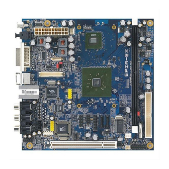
Page 12: Mainboard Layout
Chapter 1 AINBOARD AYOUT... -
Page 13: Back Panel Layout
Specifications ANEL AYOUT... -
Page 14: Back Panel Ports
Chapter 1 ANEL ORTS Port Description Page S/PDIF S/PDIF Ports DVI Port S-Video S-Video port RJ45 RJ45 port USB 2.0 ports RCA Jacks 3 Component / 3 Composite Video Ports LOTS Port Description Page DDR2 DIMM Memory module slot Expansion card slot... -
Page 15: Onboard Connectors
Specifications NBOARD ONNECTORS Connector Description Page ATXPWR Power cable connector CPUFAN CPU fan connector SYSFAN System fan connector +12V +12V power connector IDE drive connector F_PANEL Front panel connector F_AUDIO Front Audio connector KBMS Keyboard and Mouse connector LPC connector LVDS LVDS connector SATA 1-2... - Page 16 Chapter 1...
-
Page 17: Chapter 2
HAPTER Installation This chapter provides with information about hardware installation procedures. It is recommended to use a grounded wrist strap before handling computer components. Electrostatic discharge (ESD) can damage some components. -
Page 18: Cpu
Chapter 2 The VIA EPIA-EX Mini-ITX mainboard can support VIA C7 NanoBGA2 Processors. The processor requires a heatsink with fan for 1.5GHz SKU and a fanless heatsink for 1.0GHz SKU. - Page 19 Installation CPU Fan and System Fan: CPUFAN and SYSFAN The CPUFAN (CPU fan) and SYSFAN (system fan) run on +12V and maintain system cooling. When connecting the wire to the connectors, always be aware that the red wire is the Positive and should be connected to the +12V. The black wire is Ground and should always be connected to GND.
-
Page 20: Memory Module Installation
Chapter 2 EMORY ODULE NSTALLATION The VIA EPIA-EX Mini-ITX mainboard provides one 240-pin DIMM slot for DDR2 533 SDRAM memory modules and supports the memory size up to 1GB. DIMM DDR2 SDRAM Module Installation Procedures Locate the DIMM slot in the motherboard. Unlock a DIMM slot by pressing the retaining clips outward. -
Page 21: Connecting The Power Supply
Installation ONNECTING THE OWER UPPLY The VIA EPIA-EX Mini-ITX mainboard supports a conventional ATX power supply for the power system. Before inserting the power supply connector, always make sure that all components are installed correctly to ensure that no damage will be caused. ATX 20-Pin Power Connector To connect the ATX power supply, make sure the power plug is inserted in the proper orientation and the pins are aligned. -
Page 22: Back Panel Ports
Chapter 2 ANEL ORTS The back panel has the following ports: S/PDIF Ports This mainboard enables digital audio output through either the coaxial or optical SPDIF port. DVI Port The DVI-I connector allows you to connect to DVI display. S_Video Port The black port allows you to connect TV monitor or S-video device to the mainboard. - Page 23 Installation RJ45 10/100 LAN and USB Ports The mainboard provides a standard RJ-45 and two USB 2.0 ports. These ports allow connection to a Local Area Network (LAN) through a network hub and USB 2.0 devices. RCA Jack The top three RCA jacks enable you to connect to displays using component video signals.
-
Page 24: Connectors
Chapter 2 ONNECTORS Hard Disk Connectors: IDE The mainboard has an Ultra DMA 133/100/66/33 controller. You can connect up to two hard disk drives, CD-ROM and other devices. If two drives are connected to a single cable, the jumper on the second drive must be set to slave mode. - Page 25 Installation Case Connector: F_PANEL The F_PANEL pin header allows you to connect the power switch, reset switch, power LED, sleep LED, HDD LED and the case speaker. F_PANEL Signal Signal HD_LED -PLED_2 PW_BN RST_SW SPEAK -SLEEP_LED Power Switch (PW_BN) Connect to a 2-pin power button switch. Pressing this button will turn the system power on or off.
- Page 26 Chapter 2 Front Panel Audio Connector: F_AUDIO This is an interface for the VIA front panel audio cable that allow convenient connection and control of audio devices. By default, the pins labeled AUD_FPOUT_R / AUD_RET_R and the pins AUD_FPOUT_L / AUD_RET_L are shorted with jumper caps.
- Page 27 Installation LPC Connector: LPC This pin connector is for LPC devices. Signal Signal LAD1 LPCCLK1 -PCIRSTX LAD0 SIO_OSC LAD2 -LFRAME SERIRQ LAD3 -LDRQ1 -EXTSMI +3.3V +3.3V LVDS Connector The LVDS connector allows you to connect the panel’s LVDS cable directly to support LVDS panel without any need of a daughter card.
- Page 28 Chapter 2 LVDS Inverter Connector: INVERTER The mainboard provides an inverter for supplying power to the backlight of the LCD panel. Signal IVDD IVDD BLON BLON BR_CNTR Serial ATA Connectors: SATA1 and SATA2 SATA1-2 These next generation connectors support the thin Serial ATA cables for primary internal storage devices.
- Page 29 Installation USB Pin Connector: USB_1/2 The mainboard provides 2 front USB pin headers, allowing up to 4 additional USB2.0 ports up to maximum throughput of 480 Mbps. Connect each 2-port USB cable into this pin header. This port can be used to connect high-speed USB interface peripherals such as USB HDD, digital cameras, MP3 players, printers, modem and the like.
- Page 30 Chapter 2 VIP Connector Video In Port (VIP) connector is used to support the CCIR656/601 video-in/ capture function. Signal Signal CAP0D0 CAP0D7 CAP0D4 CAP0D6 CAP0D5 CAP0HS CAP0D2 CAP0D1 CAP0D3 CAP0VS CAPCLK SMBDT SMBCK SCART & D-Terminal (Optional) Mainboards fitted with the optional SCART / D-Terminal connector enables users to connect a SCART / D-Terminal port for connecting to audio/visual equipment.
-
Page 31: Jumpers
Installation UMPERS The mainboard provides jumpers for setting some mainboard functions. This section will explain how to change the settings of the mainboard functions using the jumpers. Clear CMOS: CLEAR_CMOS The onboard CMOS RAM stores system configuration data and has an onboard battery power supply. - Page 32 Chapter 2 PVDD_SEL PVDD_SEL Panel Power Selector: PVDD_SEL PVDD_SEL PVDD is the VCC selector jumper to determine the panel’s signal voltage. +12V +3.3V Setting +12V +3.3V...
-
Page 33: Slots
Installation LOTS Peripheral Component Interconnect: PCI1 The PCI slot allows you to insert PCI expansion card. When adding or removing expansion card, unplug first the power supply. Read the documentation for the expansion card if any changes to the system are necessary. -
Page 35: Chapter 3
HAPTER BIOS Setup This chapter gives a detailed explanation of the BIOS setup functions. -
Page 36: Entering Setup
Chapter 3 NTERING ETUP Power on the computer and press <Delete> during the beginning of the boot sequence to enter the BIOS setup menu. If you missed the BIOS setup entry point, you may restart the system and try again. -
Page 37: Control Keys
BIOS Setup ONTROL Keys Description Up Arrow Move to the previous item Down Arrow Move to the next item Left Arrow Move to the item in the left side Right Arrow Move to the item in the right side Enter Select the item Escape Jumps to the Exit menu or returns to the main menu from a... -
Page 38: Navigating The Bios Menus
Chapter 3 BIOS M AVIGATING THE ENUS The main menu displays all the BIOS setup categories. Use the Up/Down/ Left/Right arrow keys to select any item or sub-menu. Description of the selected/highlighted category is displayed at the bottom of the screen. An arrow symbol next to a field indicates that a sub-menu is available (see figure below). -
Page 39: Getting Help
BIOS Setup ETTING The BIOS setup program provides a “General Help” screen. You can display this screen from any menu/sub-menu by pressing <F1>. The help screen displays the keys for using and navigating the BIOS setup. Press <Esc> to exit the help screen. -
Page 40: Main Menu
Chapter 3 Phoenix - AwardBIOS CMOS Setup Utility Standard CMOS Features Load Fail-Safe Defaults Advanced BIOS Features Load Optimized Defaults Advanced Chipset Features Set Supervisor Password Integrated Peripherals Set User Password Power Management Setup Save & Exit Setup PnP / PCI Configurations Exit Without Saving Frequency/Voltage Control Esc : Quit... - Page 41 BIOS Setup Load Fail-Safe Defaults Use this menu option to load the BIOS default settings for minimal and stable system operations. Load Optimized Defaults Use this menu option to load BIOS default settings for optimal and high performance system operations. Set Supervisor Password Use this menu option to set the BIOS supervisor password.
-
Page 42: Standard Cmos Features
Chapter 3 CMOS F TANDARD EATURES Phoenix - AwardBIOS CMOS Setup Utility Standard CMOS Features Date (mm:dd:yy) Tue, 13 1999 Item Help Time (hh:mm:ss) 11 20 55 Menu Level IDE Channel 0 Master Change the day, month, year IDE Channel 0 Slave and century IDE Channel 1 Master IDE Channel 1 Slave... -
Page 43: Ide Drives
BIOS Setup IDE D RIVES Phoenix - AwardBIOS CMOS Setup Utility IDE Channel 0 Master IDE HDD Auto-Detection [Press Enter] Item Help Menu Level IDE Channel 0 Master [Auto] Access Mode [Auto] To auto-detect the HDD's size, head... on this channel Capacity 0 MB Cylinder... -
Page 44: Advanced Bios Features
Chapter 3 BIOS F DVANCED EATURES Phoenix - AwardBIOS CMOS Setup Utility Advanced BIOS Features CPU Feature [Press Enter] Item Help Hard Disk Boot Priority [Press Enter] Virus Warning [Disabled] Menu Level Quick Power On Self Test [Enabled] First Boot Device [USB-FDD] Second Boot Device [Hard Disk]... - Page 45 BIOS Setup First/Second/Third Boot Device Set the boot device sequence as BIOS attempts to load the disk operating system. Setting Description LS120 Boot from LS-120 drive Hard Disk Boot from the HDD CD-ROM Boot from CD-ROM ZIP100 Boot from ATAPI ZIP drive USB-FDD Boot from USB floppy drive USB-ZIP...
- Page 46 Chapter 3 Typematic Rate (Chars/Sec) This item sets the rate (characters/second) at which the system retrieves a signal from a depressed key. Settings: [6, 8, 10, 12, 15, 20, 24, 30] Typematic Delay (Msec) This item sets the delay between when the key was first pressed and when the system begins to repeat the signal from the depressed key.
- Page 47 BIOS Setup Full Screen Logo Show Show full screen logo during BIOS boot up process. Settings: [Enabled, Disabled] Summary Screen Show Show summary screen. Settings: [Enabled, Disabled]...
-
Page 48: Cpu Feature
Chapter 3 CPU F EATURE Phoenix - AwardBIOS CMOS Setup Utility CPU Feature Deplay Prior to Thermal [16 Min] Item Help Thermal Management [Thermal Monitor 1] Menu Level TM2 Bus Ratio [ 0 X] TM2 Bus VID [0.700V] Execute Disable Bit [Enabled] : Move Enter: Select... - Page 49 BIOS Setup TM2 Bus VID This item sets the voltage of the throttled performance that will be initiated when the on die sensor goes from not hot to hot. Settings: [0.700V, 0.716V, 0.732V, 0.748V, 0.764V, 0.780V, 0.796V, 0.812V, 0.828V, 0.844V, 0.860V, 0.876V, 0.892V, 0.908V, 0.924V, 0.940V, 0.956V, 0.972V, 0.988V, 1.004V, 1.020V, 1.036V, 1.052V, 1.068V, 1.084V, 1.100V, 1.116V, 1.132V, 1.148V, 1.164V, 1.180V, 1.196V, 1.212V, 1.228V, 1.244V, 1.260V, 1.276V, 1.292V, 1.308V, 1.324V, 1.340V, 1.356V, 1.372V, 1.388V,...
-
Page 50: Hard Disk Boot Priority
Chapter 3 RIORITY Phoenix - AwardBIOS CMOS Setup Utility Hard Disk Boot Priority Item Help Pri. Master : Pri. Slave Menu Level Sec. Master : Sec. Slave : Use < > or < > to USBHDD0 select a device, then USBHDD1 press <... -
Page 51: Advanced Chipset Features
BIOS Setup DVANCED HIPSET EATURES Phoenix - AwardBIOS CMOS Setup Utility Advanced Chipset Features [Press Enter] AGP & P2P Bridge Control Item Help CPU & PCI Bus Control [Press Enter] [Disabled] Menu Level Memory Hole [Enabled] System BIOS Cacheable [Disabled] Video RAM Cacheable [PCI Slot] Init Display First... - Page 52 Chapter 3 Select Display Device This setting refers to the type of display being used with the system. Settings: [CRT, LCD, CRT+LCD, TV, CRT+TV, LCD+TV, DVI, CRT+DVI, TV+DVI] Panel Type This setting refers to the native resolution of the display being used with the system.
-
Page 53: Agp & P2P Bridge Control
BIOS Setup AGP & P2P B RIDGE ONTROL Phoenix - AwardBIOS CMOS Setup Utility AGP & P2P Bridge Control AGP Aperture Size [128M] Item Help AGP 2.0 Mode [4x] Menu Level AGP Driving Control [Auto] x AGP Driving Value AGP Fast Write [Disabled] AGP Master 1 WS Write [Enabled]... - Page 54 Chapter 3 AGP Driving Control This item is used to signal driving current on AGP cards to auto or manual. Settings: [Auto, Manual] AGP Fast Write This item is used to enable or disable the caching of display data for the video memory of the processor.
-
Page 55: Cpu & Pci Bus Control
BIOS Setup CPU & PCI B ONTROL Phoenix - AwardBIOS CMOS Setup Utility CPU & PCI Bus Control PCI Master 0 WS Write [Enabled] Item Help PCI Delay Transaction [Enabled] Menu Level DRDY_Timing [Optimize] : Move Enter: Select +/-/PU/PD: Value F10: Save ESC: Exit F1: General Help... -
Page 56: Tv Output Connector
Chapter 3 TV O UTPUT ONNECTOR Phoenix - AwardBIOS CMOS Setup Utility TV Output Connector CVBS (Composite) [Enabled] Item Help S-Video 0 (Y/C) [Enabled] Menu Level R/G/B [Disabled] Cr/Y/Cb [Disabled] SDTV-R/G/B [Disabled] SDTV-Pr/Y/Pb [Disabled] : Move Enter: Select +/-/PU/PD: Value F10: Save ESC: Exit F1: General Help... -
Page 57: Integrated Peripherals
BIOS Setup NTEGRATED ERIPHERALS Phoenix - AwardBIOS CMOS Setup Utility Integrated Peripherals VIA OnChip PCI Device [Press Enter] Item Help USB Device Setting [Press Enter] Menu Level : Move Enter: Select +/-/PU/PD: Value F10: Save ESC: Exit F1: General Help F5: Previous Values F6: Fail-Safe Defaults F7: Optimized Defaults... -
Page 58: Via Onchip Pci Device
Chapter 3 VIA O PCI D EVICE Phoenix - AwardBIOS CMOS Setup Utility VIA OnChip PCI Device Azalia HDA Controller [Auto] Item Help OnBoard LAN Boot ROM [Disabled] Menu Level : Move Enter: Select +/-/PU/PD: Value F10: Save ESC: Exit F1: General Help F5: Previous Values F6: Fail-Safe Defaults... -
Page 59: Usb Device Setting
BIOS Setup USB D EVICE ETTING Phoenix - AwardBIOS CMOS Setup Utility USB Device Setting USB 1.0 Controller [Enabled] Item Help USB 2.0 Controller [Enabled] USB Operation Mode [High Speed] Menu Level USB Keyboard Function [Enabled] USB Storage Function [Enabled] [Enable] or [Disable] Universal Host *** USB Mass Storage Device Boot Setting ***... - Page 60 Chapter 3 USB Keyboard Function Enable or disable Legacy support of USB Keyboard Settings: [Enabled, Disabled] USB Storage Function Enable or disable Legacy support of USB Mass Storage Settings: [Enabled, Disabled] No Device Setting Description Auto mode According to contents of USB MSD decide boot up type. FDD mode The USB MSD always boot up as floppy disk.
-
Page 61: Power Management Setup
BIOS Setup OWER ANAGEMENT ETUP Phoenix - AwardBIOS CMOS Setup Utility Power Management Setup ACPI Suspend Type [S1&S3] Item Help Power Management Option [User Define] Menu Level HDD Power Down [Disabled] Suspend Mode [Disabled] Video Off Option [Suspend -> Off] Video Off Method [V/H SYNC+Blank] MODEM Use IRQ... - Page 62 Chapter 3 Video Off Option Select whether or not to turn off the screen when system enters power saving mode, ACPI OS such as Windows XP will override this option. Setting Description Always On Screen is always on even when system enters power saving mode Suspend ->...
-
Page 63: Wakeup Event Detect
BIOS Setup AKEUP VENT ETECT Phoenix - AwardBIOS CMOS Setup Utility Wakeup Event Detect [Hot Key] PS2KB Wakeup Select Item Help [Any Key] PS2KB Wakeup Key Select [Any Botton] PS2MS Wakeup Key Select Menu Level [Disabled] PS2 Keyboard Power On [Disabled] When Select Password, PS2 Mouse Power On... - Page 64 Chapter 3 PS2 Keyboard Power On Settings: [Disabled, Enabled] PS2 Mouse Power On Settings: [Disabled, Enabled] PowerOn by PCI Card Enables activity detected from any PCI card to power up the system or resume from a suspended state. Such PCI cards include LAN, onboard USB ports, etc.
-
Page 65: Pnp/Pci Configurations
BIOS Setup PNP/PCI C ONFIGURATIONS Phoenix - AwardBIOS CMOS Setup Utility PnP / PCI Configurations PNP OS Installed [No] Item Help Reset Configuration Data [Disabled] Menu Level Resources Controlled By [Auto(ESCD)] Select Yes if you are x IRQ Resources Press Enter using a Plug and Play PCI/VGA Palette Snoop [Disabled]... - Page 66 Chapter 3 Resource Controlled By Enables the BIOS to automatically configure all the Plug-and-Play compatible devices. Setting Description Auto(ESCD) BIOS will automatically assign IRQ, DMA and memory base address fields Manual Unlocks “IRQ Resources” for manual configuration PCI/VGA Palette Snoop Settings: [Disabled, Enabled] Assign IRQ For VGA/USB Assign IRQ for VGA and USB devices.
-
Page 67: Frequency / Voltage Control
BIOS Setup REQUENCY OLTAGE ONTROL Phoenix - AwardBIOS CMOS Setup Utility Frequency / Voltage Control DRAM Clock/Drive Control [Press Enter] Item Help Auto Detect PCI Clk [Enabled] Menu Level Spread Spectrum [0.25%] : Move Enter: Select +/-/PU/PD: Value F10: Save ESC: Exit F1: General Help F5: Previous Values... -
Page 68: Dram Clock/Drive Control
Chapter 3 DRAM C LOCK RIVE ONTROL Phoenix - AwardBIOS CMOS Setup Utility PnP / PCI Configurations DRAM Clock [By SPD] Item Help DRAM Timing [Auto By SPD] Menu Level x SDRAM CAS Latency [DDR/DDR 2.5 / 4 x Bank Interleave Disabled x Precharge to Active(Trp) x Active to Precharge(Tras) - Page 69 BIOS Setup Read to Precharge (Trtp) Settings: [2T, 3T] Write to Read CMD (Twtr) Settings: [1T/2T, 2T/3T] Write Recovery Time (Twr) Settings: [2T, 3T, 4T, 5T] RDSAIT mode Settings: [Manual, Auto]...
-
Page 70: Load Fail-Safe Defaults
Chapter 3 EFAULTS Phoenix - AwardBIOS CMOS Setup Utility Standard CMOS Features Frequency / Voltage Control Advanced BIOS Features Load Fail-Safe Defaults Advanced Chipset Features Load Optimized Defaults Integrated Peripherals Set Supervisor Password Power Management Setup Set User Password PnP / PCI Configurations Save &... -
Page 71: Load Optimized Defaults
BIOS Setup PTIMIZED EFAULTS Phoenix - AwardBIOS CMOS Setup Utility Standard CMOS Features Frequency / Voltage Control Advanced BIOS Features Load Fail-Safe Defaults Advanced Chipset Features Load Optimized Defaults Integrated Peripherals Set Supervisor Password Power Management Setup Set User Password PnP / PCI Configurations Save &... -
Page 72: Set Supervisor / User Password
Chapter 3 UPERVISOR ASSWORD Phoenix - AwardBIOS CMOS Setup Utility Standard CMOS Features Frequency / Voltage Control Advanced BIOS Features Load Fail-Safe Defaults Advanced Chipset Features Load Optimized Defaults Integrated Peripherals Set Supervisor Password Power Management Setup Set User Password PnP / PCI Configurations Save &... - Page 73 BIOS Setup Additionally, when a password is enabled, the BIOS can be set to request the password each time the system is booted. This would prevent unauthorized use of the system. See “Security Option” in the “Advanced BIOS Features” section for more details.
-
Page 74: Save & Exit Setup
Chapter 3 & E ETUP Phoenix - AwardBIOS CMOS Setup Utility Standard CMOS Features Frequency / Voltage Control Advanced BIOS Features Load Fail-Safe Defaults Advanced Chipset Features Load Optimized Defaults Integrated Peripherals Set Supervisor Password Power Management Setup Set User Password PnP / PCI Configurations Save &... -
Page 75: Exit Without Saving
BIOS Setup ITHOUT AVING Phoenix - AwardBIOS CMOS Setup Utility Standard CMOS Features Frequency / Voltage Control Advanced BIOS Features Load Fail-Safe Defaults Advanced Chipset Features Load Optimized Defaults Integrated Peripherals Set Supervisor Password Power Management Setup Set User Password PnP / PCI Configurations Save &... - Page 76 Chapter 3...
-
Page 77: Chapter 4
HAPTER Driver Installation This chapter gives you brief descriptions of each mainboard driver and application. You must install the VIA chipset drivers first before installing other drivers such as audio or VGA drivers. The applications will only function correctly if the necessary drivers are already installed. -
Page 78: Driver Utilities
Chapter 4 RIVER TILITIES Getting Started The mainboard includes a Driver Utilities CD that contains the driver utilities and software for enhancing the performance of the mainboard. If the CD is missing from the retail box, please contact the local dealer for the CD. Note: The driver utilities and software are updated from time to time. - Page 79 Driver Installation Running the Driver Utilities CD To start using the CD, insert the CD into the CD-ROM or DVD-ROM drive. The CD should run automatically after closing the CD-ROM or DVD-ROM drive. The driver utilities and software menu screen should then appear on the screen.
-
Page 80: Cd Content
Chapter 4 CD C ONTENT VIA 4in1 Drivers: Contains VIA ATAPI Vendor Support Driver (enables the performance enhancing bus mastering functions on ATA-capable Hard Disk Drives and ensures IDE device compatibility), AGP VxD Driver (provides service routines to your VGA driver and interface directly to hardware, providing fast graphical access), IRQ Routing Miniport Driver (sets the system's PCI IRQ routing sequence) and VIA INF Driver (enables the VIA Power Management function).
Need help?
Do you have a question about the EX10000EG - VIA EPIA Motherboard and is the answer not in the manual?
Questions and answers