Table of Contents
Advertisement
Quick Links
Advertisement
Table of Contents

Related Manuals for VIA Technologies EPIA-LT


Summary of Contents for VIA Technologies EPIA-LT
- Page 1 User’s Manual EPIA-LT Version 1.11 September 30, 2008...
- Page 2 However, VIA Technologies assumes no responsibility for the use or misuse of the information in this document and for any patent infringements that may arise from the use of this document.
- Page 3 FCC-B Radio Frequency Interference Statement This equipment has been tested and found to comply with the limits for a class B digital device, pursuant to part 15 of the FCC rules. These limits are designed to provide reasonable protection against harmful interference when the equipment is operated in a commercial environment.
-
Page 4: Safety Instructions
Safety Instructions Always read the safety instructions carefully. Keep this User's Manual for future reference. Keep this equipment away from humidity. Lay this equipment on a reliable flat surface before setting it up. The openings on the enclosure are for air convection hence protects the equipment from overheating. - Page 5 ONTENTS One VIA Mini-ITX mainboard One ATA-133/100 IDE ribbon cable One driver and utilities CD One IO bracket...
-
Page 6: Table Of Contents
ABLE OF ONTENTS Box Contents................i Table of Contents ..............ii Chapter 1 ................1 Specifications ............... 1 Mainboard Specifications ............2 Mainboard Layout ..............4 Back Panel Layout ..............5 Chapter 2 ................7 Installation................7 CPU ..................8 Memory Module Installation .......... - Page 7 USB Configuration ............... 45 Advanced PCIPnP Settings ........... 47 Boot Settings..............49 Boot Settings Configuration ..........50 Boot Device Priority ............51 Security Settings..............52 Advanced Chipset Settings ........... 53 NorthBridge VIA CX700 Configuration........54 OnChip VGA Configuration ........... 55 SouthBridge VIA CX700 Configuration ........
- Page 8 This page is intentionally left blank.
-
Page 9: Chapter 1
HAPTER Specifications The ultra-compact and highly integrated VIA EPIA-LT uses the Mini-ITX mainboard form-factor developed by VIA Technologies, Inc. part company’s open industry-wide total connectivity initiative. The mainboard enables the creation of an exciting new generation of small, ergonomic, innovative and... -
Page 10: Mainboard Specifications
Chapter 1 AINBOARD PECIFICATIONS • ® VIA C7 1.5GHz / 1.0GHz NanoBGA2 Processor Chipset • VIA CX700 Advanced All-in-One system processor Graphics • Integrated UniChrome™ Pro II 3D/2D AGP graphics with MPEG-2 video decoding acceleration Audio • VIA VT1708A High Definition Audio Codec Memory •... - Page 11 Specifications Back Panel I/O Ports • 1 x PS/2 mouse port and 1 x PS/2 keyboard port • 2 x RJ45 LAN port • 1 x VGA port • 1 x COM port • 4 x USB 2.0 ports • 3 x Audio jacks: Line-out, Line-in and Mic-in Onboard I/O Connectors •...
-
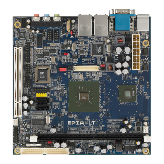
Page 12: Mainboard Layout
Chapter 1 AINBOARD AYOUT... -
Page 13: Back Panel Layout
Specifications ANEL AYOUT... - Page 14 Chapter 1 This page is intentionally left blank.
-
Page 15: Chapter 2
HAPTER Installation This chapter provides with information about hardware installation procedures. It is recommended to use a grounded wrist strap before handling computer components. Electrostatic discharge (ESD) can damage some components. -
Page 16: Cpu
Chapter 3 The VIA EPIA-LT Mini-ITX mainboard includes an embedded VIA C7 V4 Bus Processor. The VIA C7 V4 Bus Processor requires only a heatsink to provide sufficient cooling. - Page 17 BIOS Setup CPU Fan and System Fan: CPUFAN and SYSFAN The CPUFAN (CPU fan) and SYSFAN (system fan) run on +12V and maintain system cooling. When connecting the wire to the connectors, always be aware that the red wire is the Positive and should be connected to the +12V. The black wire is Ground and should always be connected to GND.
-
Page 18: Memory Module Installation
Chapter 3 EMORY ODULE NSTALLATION The VIA EPIA-LT Mini-ITX mainboard provides one 240-pin DIMM slot for DDR2 533 SDRAM memory modules and supports the memory size up to 1GB. DIMM DDR SDRAM Module Installation Procedures • Locate the DIMM slot in the motherboard. -
Page 19: Connecting The Power Supply
ONNECTING THE OWER UPPLY The VIA EPIA-LT Mini-ITX mainboard supports a conventional ATX power supply for the power system. Before inserting the power supply connector, always make sure that all components are installed correctly to ensure that no damage will be caused. -
Page 20: Back Panel Ports
Chapter 3 ANEL ORTS The back panel has the following ports: Mouse and Keyboard The connector above is for a PS/2 mouse, and the one below is for a PS/2 keyboard. Serial port: COM The 9-pin COM port is for pointing devices or other serial devices. - Page 21 BIOS Setup RJ45 10/100 LAN and USB Connectors The mainboard provides a standard RJ-45 and USB 2.0 ports. These ports allow connection to a Local Area Network (LAN) through a network hub and USB 2.0 devices. Audio Port The Line-Out jack is for connecting to external speakers or headphones.
-
Page 22: Connectors
Chapter 3 ONNECTORS Hard Disk Connectors: IDE1 The mainboard has a 32-bit Enhanced IDE and Ultra DMA 133/100/66 controller that provides PIO mode 0~4, Bus Master, and Ultra DMA 133/100/66 functions. You can connect up to four hard disk drives, CD-ROM and other devices. - Page 23 BIOS Setup Case Connector: F_PANEL The F_PANEL pin header allows you to connect the power switch, reset switch, power LED, sleep LED, HDD LED and the case speaker. F_PANEL Signal Signal +PWR_LED +HD_LED +PWR_LED -HD_LED -PWR_LED PW_BN SPEAK+ RST_SW SPEAK- +SLEEP_LED -SLEEP_LED Power Switch (PW_BN)
- Page 24 Chapter 3 Front Panel Audio Connector: F_AUDIO This is an interface for the VIA front panel audio cable that allow convenient connection and control of audio devices. By default, the pins labeled LINE_OUT_R/NEXT_R and the pins LINE_OUT_L/NEXT_L are shorted with jumper caps.
- Page 25 BIOS Setup Serial Port Connectors: COM2, COM3, and COM4 COM2/3/4 pin headers can be used to attach additional ports for serial mouse or other serial devices. COM2/3/4 Signal Signal Digital I/O Connector: DIO General purpose input and output for POS systems. Signal Signal 5V_DIO...
- Page 26 Chapter 3 LPT Connector: LPT The mainboard provides a 26-pin connector to be able to connect a 25-pin female external connector for LPT (parallel port). A parallel port is a standard printer port that supports Enhanced Parallel Port (EPP) and Extended Capabilities Parallel Port (ECP) modes.
- Page 27 BIOS Setup LVDS Panel Connector: PANEL The LVDS Panel connector allow you to connect the panel’s LVDS cable directly to support LVDS panel without any need of a daughter card. Signal Signal -LD2C4 PVDD +LD2C4 PVDD -LD2C5 +LD2C5 -LD1C0 +LD1C0 -LD2C6 +LD2C6 -LD1C1...
- Page 28 Chapter 3 MFX Pin connector This pin connector is for MFX-01 add-on cards. This pin header also allows you to connect SMBus (System Management Bus) devices (using pins 4, 6, and 8). Such devices communicate with a SMBus host and/or other SMBus devices using the SMBus interface Signal Signal...
-
Page 29: Jumpers
BIOS Setup UMPERS The mainboard provides jumpers for setting some mainboard functions. This section will explain how to change the settings of the mainboard functions using the jumpers. Clear CMOS: CLEAR_CMOS The onboard CMOS RAM stores system configuration data and has an onboard battery power supply. - Page 30 Chapter 3 Inverter Selector: IVDD_SEL IVDD is the VCC selector jumper to determine the input voltage of the panel inverter for panel’s back-light. +5V: Setting +12V: +12V Panel Power Selector: PVDD_SEL PVDD is the VCC selector jumper to determine the panel’s signal voltage. +12V +3.3V Setting...
-
Page 31: Slots
BIOS Setup LOTS Peripheral Component Interconnect: PCI The PCI slot allows you to insert PCI expansion card. When adding or removing expansion card, unplug first the power supply. Read the documentation for the expansion card if any changes to the system are necessary. - Page 32 Chapter 3 This page is intentionally left blank.
-
Page 33: Chapter 3
HAPTER BIOS Setup This chapter gives a detailed explanation of the BIOS setup functions. -
Page 34: Entering Setup
Chapter 3 NTERING ETUP Power on the computer and press <Delete> during the beginning of the boot sequence to enter the BIOS setup menu. If you missed the BIOS setup entry point, you may restart the system and try again. -
Page 35: Control Keys
BIOS Setup ONTROL Keys Description Up Arrow Move to the previous item Down Arrow Move to the next item Left Arrow Move to the previous tab Right Arrow Move to the next tab Enter Select the item Escape Jumps to the Exit menu or returns to the main menu from a submenu Increase the numeric value Decrease the numeric value... -
Page 36: Getting Help
Chapter 3 ETTING The BIOS setup program provides a “General Help” screen. You can display this screen from any menu/sub-menu by pressing <F1>. The help screen displays the keys for using and navigating the BIOS setup. Press <Esc> to exit the help screen. -
Page 37: Main Menu
BIOS Setup AMIBIOS BIOS version number and related information. Processor CPU information. System Memory Memory size. System Time Use the key “+” or “-” to configure system time. The time format is [Hour : Minute : Second]. System Date Use the key “+” or “-” to configure system Date. The date format is [Day, Month, Date, Year]. -
Page 38: Advanced Settings
Chapter 3 DVANCED ETTINGS CPU Configuration IDE Configuration Super I/O Configuration Hardware Health Configuration ACPI Configuration APM Configuration Remote Access Configuration USB Configuration... -
Page 39: Cpu Configuration
BIOS Setup CPU C ONFIGURATION CMPXCHG8B instruction support Settings: [Enabled, Disabled] VIA Processor Power Management Setting Description Enabled This selection enables CPU speed to be adjustable according to system loads in order to lower power consumption. Disabled Disable the function and CPU will be working in high speed. -
Page 40: Ide Configuration
Chapter 3 IDE C ONFIGURATION Parallel ATA IDE Controller Settings: [Disabled, Primary, Secondary, Both] Hard Disk Write Protect Settings: [Enabled, Disabled] IDE Detect Time Out (Sec) Settings: [0, 5, 10, 15, 20, 25, 30, 35] ATA(PI) 80Pin Cable Detection Settings: [Host & Device, Host, Device]... -
Page 41: Ide Drives
BIOS Setup IDE D RIVES Type Settings: [Not Installed, Auto, CD/DVD, ARMD] LBA/Large Mode Settings: [Disabled, Auto] Block (Multi-Sector Transfer) Settings: [Disabled, Auto] PIO Mode Settings: [Auto, 0, 1, 2, 3, 4] DMA Mode Settings: [Auto] S.M.A.R.T. Self Monitoring Analysis and Reporting Technology, a monitoring system for hard disks. -
Page 42: Superi/O Configuration
Chapter 3 I/O C UPER ONFIGURATION Serial Port1 Address Settings: [Disabled, 3F8, 3E8, 2E8] Serial Port1 IRQ Settings: [3, 4, 10, 11] Serial Port2 Address Settings: [Disabled, 2F8, 3E8, 2E8] Serial Port2 IRQ Settings: [3, 4, 10, 11] Serial Port2 Mode Settings: [Normal, IrDA, ASK IR] Serial Port3 Address Settings: [Disabled, A80, A88, A90, A98, AA0, AA8]... - Page 43 BIOS Setup Serial Port4 Address Settings: [Disabled, A80, A88, A90, A98, AA0, AA8] Serial Port4 IRQ Settings: [3, 4, 10, 11] Parallel Port Address Settings: [Disabled, 378, 278, 3BC] Parallel Port Mode Settings: [Normal, SPP (Bi-Dir), EPP+SPP, ECP, ECP+EPP] Parallel Port IRQ Settings: [IRQ5, IRQ7] WATCH-DOG Settings: [Disabled, Enabled]...
-
Page 44: Hardware Health Configuration
Chapter 3 ARDWARE EALTH ONFIGURATION Hardware Health Configuration This item is used to enable or disable hardware health monitoring device. Settings: [Enabled, Disabled]... -
Page 45: Acpi Settings
BIOS Setup ACPI S ETTINGS General ACPI Configuration This menu contains ACPI (Advanced Configuration and Power Management Interface) options. Advanced ACPI Configuration Chipset ACPI Configuration... -
Page 46: General Acpi Configuration
Chapter 3 ACPI C ENERAL ONFIGURATION Suspend mode Select the ACPI state used for system suspend. Setting Description S1(POS) S1/Power On Suspend (POS) is a low power state. In this state, no system context (CPU or chipset) is lost and hardware maintains all system contexts. -
Page 47: Advanced Acpi Configuration
BIOS Setup ACPI C DVANCED ONFIGURATION ACPI 2.0 Features To enable RSDP pointers to 64-bit Fixed System Description Tables. Settings: [No, Yes] ACPI APIC support To include ACPI APIC table pointer to RSDT pointer list. Settings: [Enabled, Disabled] AMI OEMB table To include OEMB table pointer to R(X)SDT pointer lists. -
Page 48: Chipset Acpi Configuration
Chapter 3 ACPI C HIPSET ONFIGURATION USB Device Wakeup Function Settings: [Enabled, Disabled]... -
Page 49: Apm Configuration
BIOS Setup APM C ONFIGURATION Power Management / APM Settings: [Disabled, Enabled] Power Button Mode Settings: [On/Off, Standby, Suspend] Suspend Power Saving Type Settings: [C3, S1] Restore on AC / Power Loss The field defines how the system will respond after an AC power loss during system operation. - Page 50 Chapter 3 Suspend Time Out Settings: [Disabled, 1/2/4/8/10/20/30/40 minutes] Hard Disk Time Out Settings: [Disabled, 1/2/3/4/5/6/7/8 minutes] Green PC Monitor Power State Settings: [Standby, Suspend, Off] Video Power Down Mode Settings: [Disabled, Standby, Suspend] Hard Disk Power Down Mode Settings: [Disabled, Standby, Suspend] Display Activity Settings: [Ignore, Monitor] Monitor IRQ3~15...
- Page 51 BIOS Setup Resume on PS/2 Mouse Enables any mouse activity to restore the system from the power saving mode to an active state. Settings: [Disabled, S3, S3/S4/S5] Resume on RTC Alarm Sets a scheduled time and/or date to automatically power on the system. Settings: [Disabled, Enabled]...
-
Page 52: Remote Access Configuration
Chapter 3 EMOTE CCESS ONFIGURATION Remote Access To select Remote Access type. Settings: [Disabled, Enabled]... -
Page 53: Usb Configuration
BIOS Setup USB C ONFIGURATION USB 1.1 Ports Configuration To enable USB 1.1 host controllers. Settings: [Disabled, USB 2 ports, USB 4 ports, USB 6 ports] USB 2.0 Ports Enable To enable USB 2.0 host controllers. Settings: [Disabled, Enabled] Legacy USB Support To enable support for legacy USB. - Page 54 Chapter 3 USB 2.0 Controller Mode To configure the USB 2.0 controller in HiSpeed (480Mbps) or FullSpeed (12Mbps). Settings: [HiSpeed, FullSpeed]...
-
Page 55: Advanced Pcipnp Settings
BIOS Setup PCIP DVANCED ETTINGS Note: This section covers some very technical items and it is strongly recommended to leave the default settings as it is unless you are an experienced user. Clear NVRAM To clear NVRAM during system boot. Settings: [No, Yes] Plug &... - Page 56 Chapter 3 Palette Snooping Settings: [Disabled, Enabled] PCI IDE BusMaster Settings: [Disabled, Enabled] IRQ3~15 Settings: [Available, Reserved] DMA Channel 0~7 Settings: [Available, Reserved] Reserved Memory Size To decide the size of memory block to reserve for legacy ISA devices. Settings: [Disabled, 16k, 32k, 64k]...
-
Page 57: Boot Settings
BIOS Setup ETTINGS Boot Settings Configuration Configuration settings during system boot. Boot Devices Priority Specifies the boot device priority sequence. -
Page 58: Boot Settings Configuration
Chapter 3 ETTINGS ONFIGURATION Quick Boot Settings: [Disabled, Enabled] Quiet Boot Settings: [Disabled, Enabled] AddOn ROM Display Mode Settings: [Force BIOS, Keep Current] Bootup Num-Lock To select power-on state for Num-Lock. Settings: [Off, On] PS/2 Mouse Support Settings: [Disabled, Enabled, Auto]... -
Page 59: Boot Device Priority
BIOS Setup EVICE RIORITY 1st Boot Device To specifies the boot sequence from the available devices. The available boot devices are detected dynamically according to real situation and variable options will be provided. Settings: [Network:VIA BootAgent, Disabled] 2nd Boot Device Settings: [Network:VIA BootAgent, Disabled]... -
Page 60: Security Settings
Chapter 3 ECURITY ETTINGS Change Supervisor Password This option is for setting a password for entering BIOS Setup. When a password has been set, a password prompt will be displayed whenever BIOS Setup is run. This prevents an unauthorized person from changing any part of your system configuration. -
Page 61: Advanced Chipset Settings
BIOS Setup DVANCED HIPSET ETTINGS Caution: The Advanced Chipset Settings menu is used for optimizing the chipset functions. Do not change these settings unless you are familiar with the chipset. North Bridge VIA CX700 Configuration South Bridge VIA CX700 Configuration... -
Page 62: Northbridge Via Cx700 Configuration
Chapter 3 VIA CX700 C ORTH RIDGE ONFIGURATION Top Performance Settings: [Disabled, Enabled] Software Reset E2 issue Settings: [Patch, Escape Patch]... -
Page 63: Onchip Vga Configuration
BIOS Setup VGA C ONFIGURATION VGA Frame Buffer Size Settings: [32MB, 64MB, 128MB] CPU Direct Access Frame Buffer Settings: [Disabled, Enabled] Select Display Device Settings: [CRT, LCD, TV, HDTV, CRT+LCD, LCD+TV] Panel Type Settings: [02] Outport Port Settings: [DI0, DI1] Dithering Settings: [Disabled, Enabled]... - Page 64 Chapter 3 TV H/W Layout Settings: [Default, Composite+S-Video, S-Video+S-Video, Comp.+R/G/B, Comp.+Y/Cb/Cr, Comp.+SDTV-R/G/B, Comp.+SDTV-Y/Pb/Pr, Composite, S- Video] TV Type Settings: [NTSC, PAL/PAL B/PAL G/PAL H, PAL M, PAL N, PAL Nc, PAL I, PAL D, NTSC Japan] TV Output Connector Settings: [CVBS (Composite), S-Video 0 (Y/C), R/G/B, Cr/Y/Cb, SDTV-R/G/B, SDTV-Pr/Y/Pb, S-Video 1 (Y/C)] HDTV Type Settings: [SDTV 525I/480I NTSC, SDTV 625I/576I PAL, HDTV 480P/525P...
-
Page 65: Southbridge Via Cx700 Configuration
BIOS Setup VIA CX700 C OUTH RIDGE ONFIGURATION Serial ATA IDE Controller Settings: [IDE, RAID] MC’97 Modem Settings: [Disabled, Auto] High Definition Audio Settings: [Disabled, Auto]... -
Page 66: Exit Options
Chapter 3 PTIONS Save Changes and Exit Exit system setup after saving the changes, or press “F10”. Discard Changes and Exit Exit system setup without saving any changes, or press “Esc”. Discard Changes Discard changes which have been done so far to any of the setup questions, or press “F7”. -
Page 67: Chapter 4
HAPTER Driver Installation This chapter gives you brief descriptions of each mainboard driver and application. You must install the VIA chipset drivers first before installing other drivers such as audio or VGA drivers. The applications will only function correctly if the necessary drivers are already installed. -
Page 68: Driver Utilities
Chapter 4 RIVER TILITIES Getting Started The Driver Utilities CD contains the driver utilities and software for enhancing the performance of the mainboard. Note: The driver utilities and software are updated from time to time. The latest updated versions are available at http://www.viaembedded.com/... - Page 69 Driver Installation Running the Driver Utilities CD To start using the CD, insert the CD into the CD-ROM or DVD-ROM drive. The CD should run automatically after closing the CD-ROM or DVD-ROM drive. The driver utilities and software menu screen should then appear on the screen.
-
Page 70: Cd Content
VIA USB 2.0 Driver: Enhances VIA USB 2.0 ports. VIA LAN Driver: Enhances the onboard VIA 10/100M LAN chip. VIA RAID Driver: Support for SATA RAID devices. Note: EPIA-LT does not support video outputs of HDTV (YPbPr) and LCD. Please DO NOT enable these functions in this system.
Need help?
Do you have a question about the EPIA-LT and is the answer not in the manual?
Questions and answers