Table of Contents
Advertisement
Quick Links
Advertisement
Table of Contents

Subscribe to Our Youtube Channel
Related Manuals for EUROCOM D270ES VIPER


Summary of Contents for EUROCOM D270ES VIPER
-
Page 2: Trademarks
Preface Notice The company reserves the right to revise this publication or to change its contents without notice. Infor- mation contained herein is for reference only and does not constitute a commitment on the part of the man- ufacturer or any subsequent vendor. They assume no responsibility or liability for any errors or inaccuracies that may appear in this publication nor are they in anyway responsible for any loss or damage resulting from the use (or misuse) of this publication. -
Page 3: Fcc Statement
Preface FCC Statement (Federal Communications Commission) This equipment has been tested and found to comply with the limits for a Class B digital device, pursuant to Part 15 of the FCC Rules. These limits are designed to provide reasonable protection against harmful interference in a residential installation. -
Page 4: Important Safety Instructions
Preface IMPORTANT SAFETY INSTRUCTIONS When using your telephone equipment, basic safety precautions should always be followed to reduce the risk of fire, electric shock and injury to persons, including the following: Do not use this product near water, for example near a bath tub, wash bowl, kitchen sink or laundry tub, in a wet basement or near a swimming pool. -
Page 5: Instructions For Care And Operation
Preface Instructions for Care and Operation The notebook computer is quite rugged, but it can be damaged. To prevent this, follow these suggestions: Don’t drop it, or expose it to shock. If the computer falls, the case and the components could be damaged. - Page 6 Preface Avoid interference. Keep the computer away from high capacity transformers, electric motors, and other strong magnetic fields. These can hinder proper performance and damage your data. Follow the proper working procedures for the computer. Shut the computer down properly and don’t forget to save your work.Remember to periodically save your data as data may be lost if the battery is depleted.
-
Page 7: Power Safety
Preface Power Safety The computer has specific power requirements: • Only use a power adapter approved for use with this computer. • Your AC adapter may be designed for international travel but it still requires a steady, uninterrupted power supply. If you are unsure of your local power specifi- Power Safety cations, consult your service representative or local power company. -
Page 8: Battery Precautions
Preface Battery Precautions • Only use batteries designed for this computer. The wrong battery type may explode, leak or damage the com- puter. • Recharge the batteries using the notebook’s system. Incorrect recharging may make the battery explode. • Do not try to repair a battery pack. Refer any battery pack repair or replacement to your service representative or qualified service personnel. -
Page 9: Cleaning
Preface Cleaning Do not apply cleaner directly to the computer, use a soft clean cloth. Do not use volatile (petroleum distillates) or abrasive cleaners on any part of the computer. Servicing Do not attempt to service the computer yourself. Doing so may violate your warranty and expose you and the computer to electric shock. -
Page 10: Travel Considerations
Preface Travel Considerations Packing As you get ready for your trip, run through this list to make sure the system is ready to go: Check that the battery pack and any spares are fully charged. Power off the computer and peripherals. Close the display panel and make sure it’s latched. - Page 11 Preface On the Road In addition to the general safety and maintenance suggestions in this preface, and Chapter 8: Troubleshoot- ing, keep these points in mind: Hand-carry the notebook: For security, don’t let it out of your sight. In some areas, computer theft is very common.
- Page 12 Preface Developing Good Work Habits Developing good work habits is important if you need to work in front of the computer for long periods of time. Improper work habits can result in discomfort or serious injury from repetitive strain to your hands, wrists or other joints.
- Page 13 Preface Lighting Proper lighting and comfortable display viewing angle can reduce eye strain and muscle fatigue in your neck and shoulders. • Position the display to avoid glare or reflections from overhead lighting or outside sources of light. • Keep the display screen clean and set the brightness and contrast to levels that allow you to see the screen clearly.
-
Page 14: Table Of Contents
Preface Contents Top View ..............1-7 Top View with LCD Panel Open ....... 1-8 Notice ................ I LCD Panel ............1-9 Trademarks ............I Microphone ............ 1-9 FCC Statement ..........II Close Cover Switch ........1-9 Instructions for Care and Operation ....IV LED Status Indicators ........ - Page 15 Preface Printer/Parallel Port ........1-18 The CD/DVD Device ..........2-9 RJ-11 Phone Jack .........1-18 Loading Discs ............ 2-9 Vent ..............1-18 Handling CDs or DVDs ........2-10 External Monitor (CRT) Port .......1-19 DVD Regional Codes ........2-11 2 * USB Ports ..........1-19 Changing DVD Regional Codes ....
- Page 16 Preface Video Driver Controls ..........3-3 Configuring the Power Button ......3-22 Making Adjustments for the Display ....3-3 Battery Information ..........3-23 Display Properties ..........3-4 New Battery ..........3-23 SiS Utility Tray/Manager ........3-5 Battery Life ..........3-23 Video Memory ............3-7 Battery FAQ ............. 3-24 Display Devices ............3-8 Conserving Battery Power .......
- Page 17 Preface Video (WinXP) ...........4-9 Removing the Battery ..........6-3 USB 2.0 (WinXP) ..........4-9 Battery Removal Process ........6-3 Hot-Key (WinXP) ..........4-9 Upgrading the Hard Disk Drive ....... 6-4 TouchPad (WinXP) ..........4-10 Hard Disk Upgrade Process ....... 6-4 Upgrading the System Memory (RAM) ....6-6 BIOS Utilities .......5-1 Memory Upgrade Process ........
- Page 18 Preface Processor ............. A-1 Core Logic ............A-1 Structure .............. A-2 Security ..............A-2 Memory ............... A-2 BIOS ..............A-2 Display ..............A-2 LCD Options ............A-3 Storage Devices ........... A-3 Audio ..............A-3 Keyboard ............. A-3 PC Card ............... A-3 Interface ...............
- Page 19 Preface XVIII...
-
Page 20: Introduction
Introduction Chapter 1: Introduction Overview Notes Check the light colored This manual refers to the hardware and essential software required to run your boxes with the mark notebook computer. Depending on how your system is configured, some or all above to find detailed of the features described may already be set up. -
Page 21: Warning Boxes
Introduction Warning Boxes No matter what your level please pay careful attention to the warning and safe- ty information indicated by the symbol. Also please note the safety and handling instructions as indicated in the Preface . Not Included Operating Systems (e.g. Windows 2000 Professional, Windows XP etc.) have their own manuals, as do applications (e.g. -
Page 22: Quick Start Guide
Introduction Quick Start Guide This guide assumes that you are already familiar with computers and can tell at a glance what and where all the key components are. If you are not that com- Peripheral Devices fortable with this type of device, then please refer to the following pages, Please note that pe- which give an overview of the system. -
Page 23: System Map
Introduction System Map Your computer has a lot of built-in features. Most of these are enabled by your operating system. Further explanations of the various subsystems are covered Design Differences in the chapter or pages indicated. This manual refers to the two notebook de- Getting to Know Your Computer signs pictured on this... -
Page 24: Model Types
Introduction Model Types In addition to the two external designs mentioned on page 1-4, this notebook series includes three model types according to their specifications (a total of AC Adapter Table 1 - 1 on page 1 - 6 six different combinations). will help you identify Warning your model type:... -
Page 25: Model Differences
Introduction Feature Model A Model B Model C Table 1 - 1 Model Differences CPUs Mobile or Desktop Mobile or Desktop Mobile or Desktop Supported 2.0 (install drivers - USB Port Type Table 4 - 1 on page 4 - 3 IEEE 1394 Port Yes (install drivers - Yes (install drivers -... -
Page 26: Top View
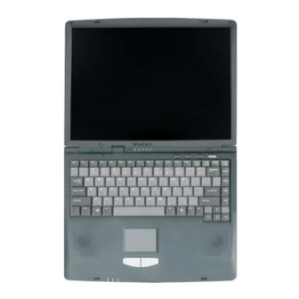
Introduction Top View Figure 1 - 2 Top View with LCD Panel Closed LCD Latch To open the LCD display: 1. Place the computer on a stable surface. 2. Move the LCD latch to the right, and hold it to release the top cover. 3. -
Page 27: Top View With Lcd Panel Open
Introduction Top View with LCD Panel Open Figure 1 - 3 Top View with LCD Panel Open LCD Panel Built-In Microphone Close Cover Switch LED Status Indicators Hot-Key buttons Power Button Keyboard Speakers TouchPad and Buttons 10. LED Power Indicators 1 - 8 Top View... -
Page 28: Lcd Panel
Introduction LCD Panel The computer comes with a 13.3" OR a 14.1" TFT (Liquid Crystal Display) screen, depending upon the configuration purchased. See “LCD Options” on page A - 3 for details. Microphone Record on your notebook computer with the built-in microphone. Close Cover Switch This switch acts as a sensor to tell when the LCD Panel is closed. -
Page 29: Hot-Key Buttons
Introduction Hot-Key Buttons The three hot-keys allow you instant access to your default Internet browser, default e-mail program, and an application of your choice. To learn how to set the buttons, see “Hot-Keys” on page 2 - Power Button Press this button to turn your computer on or off (see “Turning on the Computer”... -
Page 30: Keyboard
Introduction Keyboard The computer has a “Win Key” keyboard including a numeric keypad. It has the same features as a full-sized desktop keyboard and can easily be replaced with a different language keyboard should you desire. Stereo Speakers Two built-in speakers provide rich, stereo sound. TouchPad &... -
Page 31: Left Side View
Introduction Left Side View Figure 1 - 4 Front View S/PDIF Out Port / Microphone-In Jack Headphone-Out Jack Volume Control Knob PC Card Slot Infrared Transceiver 3.5” FDD Y-cable for S/PDIF Out/Microphone-In S/PDIF Out Port / Microphone-In Jack You can use this port for S/PDIF (Sony/Philips Digital Interface Format) output, and to record on your notebook computer with an external micro- phone. -
Page 32: Headphone-Out Jack
Introduction Headphone-Out Jack Headphones may be connected through this jack. Note: Set your system’s vol- ume to a reduced level before connecting to this jack. Volume Control Knob Adjust the audio volume with this knob. The audio volume can also be ad- justed in the operating system. -
Page 33: Pc Card Slot
Introduction PC Card Slot For Models A & B only - This is a Type-II 3.3V/5V PC card slot (also pre- viously referred to as PCMCIA) supporting CardBus. Refer to “The PC Infrared Communication Card Slot” on page 2 - 13 for more information. -
Page 34: Right Side View
Introduction Right Side View Figure 1 - 5 Left Side View Security Lock Slot Vent CD Device Bay Security Lock Slot To prevent possible theft, a Kensington-type lock can be attached to this slot. Locks can be purchased at any computer store. Vent Overheating This enables airflow to prevent the notebook from overheating. - Page 35 Introduction CD Emergency Eject If you need to manually eject a CD/DVD (e.g. due to an unexpected power interrup- tion) you may push the end of a straightened paper clip into the emergency eject hole. Do not use a sharpened pencil or similar object that may break and become lodged in the hole.
-
Page 36: Rear View
Introduction Rear View Figure 1 - 7 Rear View DC-In Jack PS/2 Type Port Parallel Port RJ-11 Phone Jack Vent External Monitor (CRT) Port Overheating 2 * USB Ports S-Video-Out Port To prevent your com- IEEE 1394 Port puter from overheating make sure nothing... -
Page 37: Ps/2 Type Port
Introduction PS/2 Type Port Connect an external PS/2 type mouse or keyboard to this port. You can use a “Y” splitter if you want to attach both. Printer/Parallel Port This port supports ECP (Extended Capabilities Port) and EPP (Enhanced Parallel Port) 1.7/1.9 modes. RJ-11 Phone Jack This port connects to the built-in modem. -
Page 38: External Monitor (Crt) Port
Introduction External Monitor (CRT) Port Connect an external VGA monitor (CRT) to this port to allow dual video or simultaneous display on the LCD and external VGA monitor (see “Display Devices” on page 3 - 2 * USB Ports Depending on the model you purchase, the USB ports which come with your notebook can be either USB 1.1 compatible or USB 2.0 compatible. -
Page 39: Ieee 1394 Port
Introduction IEEE 1394 Port For Models A& B only - This allows high speed connection to various pe- ripheral devices, e.g. external disk drives and digital cameras (see note be- low). IEEE 1394 The IEEE 1394 port only supports SELF POWERED IEEE 1394 devices. RJ-45 LAN Jack This port supports LAN (Network) functions. -
Page 40: Bottom View
Introduction Bottom View Figure 1 - 8 Bottom View RAM Cover Vent Battery The CPU is not a user serviceable part. Opening compartment, or ac- cessing the CPU in any way, may violate your warranty. Overheating To prevent your com- Vent puter from overheating This enables airflow to prevent the notebook from overheating. - Page 41 Introduction 1 - 22...
-
Page 42: Using The Computer
Using The Computer Chapter 2: Using The Computer Overview To learn more about using your computer, please read this chapter. This chapter includes: • The Power Sources • Turning on the Computer • The LED Indicators • The Hard Disk Drive •... -
Page 43: The Power Sources
Using The Computer The Power Sources The computer can be powered by either an AC adapter or a battery pack. Power Button as Standby or Hibernate AC Adapter Button Use only the AC adapter that comes with your computer. The wrong type of If you are using a fully AC adapter will damage the computer and its components. -
Page 44: Recharging The Battery With The Ac Adapter
Using The Computer Recharging the Battery with the AC Adapter The battery pack automatically recharges when the AC adapter is attached and plugged into an electrical outlet. If the computer is powered on, and in use, it Battery Removal will take several hours to fully recharge the battery. When the computer is We recommend that turned off but plugged into an electrical outlet, battery charge time is less (re- you do not remove the... -
Page 45: Turning On The Computer
Using The Computer Turning on the Computer Now you are ready to begin using your computer. To turn it on simply press the power button on the front panel. Forced Off If the system “hangs” When the computer is on, you can use the power button as a Standby/Hiber- and the Ctrl + Alt + Del nate/Shutdown hot-key button when it is pressed for less than 4 seconds combination... -
Page 46: Led Indicators
Using The Computer LED Indicators There are two sets of LED indicators (LED Status Indicators and LED Power Indicators ) on your computer that will display helpful information about the current status of the computer. The LED Power Indicators are also visible when the top of your computer is closed. -
Page 47: Led Status & Power Indicators
Using The Computer LED Status & Power Indicators Icon Color Description Table 2 - 1 Green Floppy Disk Drive is being accessed LED Status & Power Indicators Green Hard disk/CD Device is being accessed Green Number Lock is activated Green Caps Lock is activated Green Scroll Lock is activated (to activate press Fn &... -
Page 48: The Hard Disk Drive
Using The Computer The Hard Disk Drive The hard disk drive is used to store your data in the computer. The hard disk is mounted in a removable case and can be taken out to accommodate other Power Safety 2.5" IDE hard disk drives with a height of 9.5/12.7 mm. The system supports Before attempting to DMA mode 2 / PIO mode 4 / ATA-33/66/100. -
Page 49: The Floppy Disk Drive (Fdd)
Using The Computer The Floppy Disk Drive (FDD) Optional for Model C - The computer is equipped with a fixed 1.44 MB, 3.5" floppy disk drive module. By default it is drive “A:” and can be used as a boot Media Warning device if properly set in the BIOS (refer to “Boot Menu”... -
Page 50: The Cd/Dvd Device
Using The Computer The CD/DVD Device There are bays for a combination of a CD-ROM, or DVD-ROM, or CD-RW, or Combination CD-RW and DVD-ROM drive depending on the model you Sound Volume Adjustment purchased. You may alternatively have a hard disk or IP sharing module in the modular drive bay (Bay Two). -
Page 51: Handling Cds Or Dvds
Using The Computer Handling CDs or DVDs Proper handling of your CDs/DVDs will prevent them from being damaged. Please follow the advice below to make sure that the data stored on your CD- CD Emergency Eject ROMs/DVD-ROMs can be accessed. If you need to manually Remember to: eject a CD (e.g. -
Page 52: Dvd Regional Codes
Using The Computer DVD Regional Codes DVD region detection is device dependent, not OS-dependent. You can select your module’s region code 5 times. The fifth selection is permanent. This can- not be altered even if you change your operating system or you use the module in another computer. -
Page 53: Changing Dvd Regional Codes
Using The Computer Changing DVD Regional Codes Go to the Control Panel in WindowsXP/Windows 2000 and double-click Sys- tem > Hardware (tab), click Device Manager, then click the + next to DVD/ CD-ROM drives. Double-click on the DVD-ROM device to bring up the Properties menu, and select the DVD Region (tab) to bring up the control panel as seen in “DVD Regional Codes (Windows XP)”... -
Page 54: The Pc Card Slot
Using The Computer The PC Card Slot Only Models A & B are equipped with a PCMCIA 3.3V/5V slot for one Type II PC Card. Make sure you install the driver for the PC Card (see “What to Install” on page 4 - Inserting and Removing PC Cards •... -
Page 55: Hot-Keys
Using The Computer Hot-Keys The computer has three Hot-Key buttons on the computer, and the function key combinations on the keyboard. Non-Default E-Mail and Browser Programs Hot-Key Buttons It is possible to config- These keys access the internet, e-mail or a user-defined application with one ure both the email and quick button press. - Page 56 Using The Computer To configure and specify an application for Application 1 (the default Hot- Key setting is for the CD Player application), you must follow the instruc- tions below. Application.exe Right click the Hot-Key driver icon on the taskbar and the following You will need to locate menu will appear.
-
Page 57: Function Keys And Numeric Keypad
Using The Computer Function Keys and Numeric Keypad Function Keys Other Keyboards On the bottom-left of the keyboard is the Fn key or Function key. The Fn key If your keyboard is allows you to change operational features instantly. To use the functions press damaged or you just and hold the Fn key, then press the appropriate function key (F3, F5, etc.) lo- want... - Page 58 Using The Computer Figure 2 - 6 Keyboard Special Characters Some software appli- cations allow number-keys used with Alt to pro- duce special charac- Keys Description ters. These special Function Key characters can only be produced by using the Fn + Esc Suspend/Resume Toggle numeric keypad.
-
Page 59: Touchpad And Buttons/Mouse
Using The Computer TouchPad and Buttons/Mouse The TouchPad is a device for pointing (controlling input positioning) on the computer’s display screen by sensing finger movement, and downward pres- Mouse Driver sure. It is an alternative to the mouse, however, you can also add a mouse to If you are using an ex- your computer either through the PS/2 interface, or one of the USB ports. - Page 60 Using The Computer Easy Launcher You can add programs to the menu from the Others Mouse control panel Click on Settings for Easy Launcher to get the settings options. Click the New button and browse to any pro- grams you wish to add to the menu.
-
Page 61: Adding A Printer
Using The Computer Adding a Printer The most commonly used peripheral is a printer. The following conventions will help you to add a printer, however it is always best to refer to the printer manual for specific instructions and configuration options. USB Printer Most new printers have a USB interface connection. -
Page 62: Parallel Printer
Using The Computer Parallel Printer This is still the most common type of printer. Install Instructions: Set up the printer according to its instructions (unpacking, paper tray, toner/ ink cartridge etc.). Attach the parallel cable to the printer. Connect the printer’s parallel cable to the parallel port at the rear of the computer (see “Rear View”... - Page 63 Using The Computer 2 - 22...
-
Page 64: Advanced Controls
Advanced Controls Chapter 3: Advanced Controls Overview This chapter covers: Drivers • Advanced video controls • Power and battery management features You are unable to use most advanced con- trols until the neces- sary drivers utilities are properly in- stalled. If your system hasn’t been properly configured (your serv- ice representative may... -
Page 65: Advanced Video Controls
Advanced Controls Advanced Video Controls This section is about making adjustments for the LCD, and switching display devices. Protecting the LCD Do not allow any for- Opening the LCD eign objects (i.e. paper As you open the lid, adjust it so you can look at the screen straight on, without or plastic) to get be- tween the lid/LCD and any glare. -
Page 66: Video Driver Controls
Advanced Controls Video Driver Controls The video interface lets you change the screen resolution and color output to whatever is most comfortable/efficient for you. This is a matter of hardware, Screen Resolution/ Screen Area Note video memory and the driver for your operating system. The driver interface shows the available options (see “Display”... -
Page 67: Display Properties
Advanced Controls Display Properties Figure 3 - 2 Advanced Display Properties When the Display Properties control panel is open, click the Advanced (button) to bring up the options tabs. Clicking through these tabs allows you to make any video adjustments you require. 3 - 4 Video Driver Controls... -
Page 68: Sis Utility Tray/Manager
Advanced Controls SiS Utility Tray/Manager With the video driver installed additional control panels are available. To get to the control panels do the following: Click Start, point to Settings and click Control Panel (if you are in Cate- gory View choose Appearance and Themes). Double-click Display (icon). - Page 69 Advanced Controls You may make changes to the Driver Mode Settings, Video Settings, Gamma Correction Settings and view General Information by clicking the appropriate tab and adjusting the setting. Some screen examples are shown below. Figure 3 - 4 SiS Utility Tray/ Manager Setting Tabs 3 - 6 Video Driver Controls...
-
Page 70: Video Memory
Advanced Controls Video Memory The computer does not have dedicated video memory. It makes use of a por- tion of system memory as video memory. By default, the video memory is set Video Memory Usage to 32MB. You may also set it to 16MB or 64MB (maximum) in the BIOS (see 3D Applications, such “Embedded Share Memory (Advanced Menu>Advanced Chipset Control)”... -
Page 71: Display Devices
Advanced Controls Display Devices Besides the built-in LCD, you can also use an external VGA monitor (CRT) or TV as your display device. A VGA monitor connects to the external mon- VGA Monitor and TV Display Setting itor (CRT) port a TV to the S-Video out port , as seen in Figure 3 -... -
Page 72: Display Options
Advanced Controls Display Options Multiple Display Modes & DVD Display Mode Windows XP Windows 2000 Playback In Mirror mode DVD Single movies must be dis- played in the primary Mirror device - “Switch- ing/Enabling Dis- Multimonitor Not Available plays (Driver)” page 3 - Single - Either the LCD, VGA monitor or TV as a display device. -
Page 73: Switching/Enabling Displays (Keyboard)
Advanced Controls Switching/Enabling Displays (Keyboard) To simply switch display devices, or enable other devices, with the Fn + Display (F6) toggle do the following: 1. Plug the VGA monitor or TV into the appropriate port. 2. Press and hold the Fn key, while simultaneously pressing the F6 key. 3. -
Page 74: Switching/Enabling Displays (Driver)
Advanced Controls Switching/Enabling Displays (Driver) With the video driver installed (see “What to Install” on page 4 - 2), you can use its built-in controls to switch between the displays as follows: 1. Plug the VGA monitor or TV into the appropriate port. 2. -
Page 75: Mirror Mode
Advanced Controls Mirror Mode In this mode the display of the two devices is the same. Mirror mode simply shows an exact copy of the Primary display desktop on the Secondary dis- Switching Display play. This mode will drive multiple displays with the same content. Use this Modes feature to display the screen through a projector for a presentation etc. -
Page 76: Multimonitor
Advanced Controls Multimonitor This mode allows a desktop to span the displays to act as a large work area, thus creating a lot more screen area for display. Figure 3 - 7 Multimonitor Setting Setting Multimonitor Mode 1. Follow the instructions in “Switching/Enabling Displays (Driver)”... - Page 77 Advanced Controls Configuring Multimonitor Displays You can reconfigure the displays in Multimonitor mode from the Display Properties > Settings control panel (see “Multimonitor Setting” on page 3 - 13). Make sure you have checked the “Extend my Windows desktop onto this monitor.”...
-
Page 78: Adjusting Monitor Settings
Advanced Controls Adjusting Monitor Settings If you prefer to use a VGA monitor (CRT) you may change the vertical re- Vertical Refresh Rate fresh rate from the following control panel. Double-click on the VGA monitor icon (in the example below it is the icon as the VGA is set for The vertical refresh rate Display_2). -
Page 79: Tv Display
Advanced Controls TV Display To display desktop images on a TV display, connect the TV to your com- VGA Monitor and TV puter by using an S-Video cable from the TV to the port at the rear of the Display Setting computer. -
Page 80: Power Management Features
Advanced Controls Power Management Features To conserve power, especially when using the battery, your notebook comput- er uses the ACPI power management system. Power management conserves OS Note power by controlling individual components of the computer (the monitor and Power management hard disk drive) or the whole system. -
Page 81: Enabling Power Options
Advanced Controls Enabling Power Options Power Options are enabled through the control panel in your Windows sys- tem (Power Options). With other operating systems you may have power management available, so check your documentation. Figure 3 - 11 Power Options Control Panel You may conserve power through individual components or throughout the whole system. -
Page 82: Conserving Power (Individual Components)
Advanced Controls Conserving Power (Individual Components) Turn off Monitor Resuming Operation To conserve power, you can set the monitor to turn off after a specified time. system resume from Monitor Turn off Hard Disk or Hard Disk Standby by pressing a key on The computer's hard disk motor will be turned off if the hard disk drive has the keyboard. -
Page 83: Conserving Power (System)
Advanced Controls Conserving Power (System) With this function you can stop the notebook’s operation and restart where you left off. This system features Standby and Hibernate sleep mode levels (Hibernate mode will need to be enabled by clicking the option in the Hiber- nate tab in the Power Options control panel - Figure 3 - 13 on page 3 - 21). -
Page 84: Standby
Advanced Controls Standby Standby saves the least amount of power, but takes the shortest time to return to full operation. During Standby the hard disk is turned off, and the CPU is System Resume made to idle at its slowest speed. All open applications are retained in memo- system ry. -
Page 85: Configuring The Power Button
Advanced Controls Configuring the Power Button The power button may be set to send the computer in to either Standby or Hi- bernate mode (Figure 3 - 14). In Standby mode, the LED will flash Sleep Button green. In Hibernate mode the LED will be off. If you are in a power saving mode set to save power through individual components (e.g. -
Page 86: Battery Information
Advanced Controls Battery Information Please follow these simple guidelines to get the best use out of your battery. Caution New Battery Danger of explosion if Always completely discharge, then fully charge, a new battery before using it battery is incorrectly (see “Battery FAQ”... -
Page 87: Battery Faq
Advanced Controls Battery FAQ How do I completely discharge the battery? Use the computer with battery power until it shuts down due to a low battery. Conserving Battery Don’t turn off the computer by yourself even when you see a message that in- Power dicates the battery is critically low, just let the computer use up all of the bat- To conserve battery... -
Page 88: Configuring The Infrared Settings For Fir
Advanced Controls Configuring the Infrared Settings for FIR For Models A & B only - Users will need to change the settings for the infra- red device in the BIOS (see “I/O Device Configuration (Advanced Menu)” Infrared Communication on page 5 - 12) to enable the FIR setting support. - Page 89 Advanced Controls 3 - 26...
-
Page 90: Drivers & Utilities
Drivers & Utilities Chapter 4: Drivers & Utilities Overview This chapter deals with installing the drivers and utilities essential to the operation or improvement Assumption of some of the computer’s subsystems. The system takes advantage of some newer hardware compo- We assume that you will install all drivers and utilities nents for which the latest versions of most available from the built-in CD device and it is assigned to “Drive... -
Page 91: What To Install
Drivers & Utilities What to Install The Device Drivers & Utilities + User’s Manual CD-ROM contains the drivers and utilities neces- sary for the proper operation of the computer Navigate (Browse..) to D: Table 4 - 1 on page 4-3 lists what you need to in- You will notice that many of the instructions for driver stall manually according to your choice of the oper-... -
Page 92: Authorized Driver Message
Drivers & Utilities Authorized Driver Message Windows If you receive a message telling you that the driver Feature Windows 2000 you are installing is not authorized (Digital Signa- ture Not Found), just click Yes or Continue Any- Audio page 4 - 4 page 4 - 7 way to ignore the message and continue the Modem... -
Page 93: Windows 2000 Professional
Drivers & Utilities Windows 2000 Professional Modem (Win2000) This section covers driver and utility installation in- structions for Windows 2000 Professional. 1. Click Start (menu), point to Settings and click Control Panel. Double-click System Audio (Win2000) (icon) and then click Hardware (tab) > 1. -
Page 94: Lan (Win2000)
Drivers & Utilities 10. The modem is ready for dial-up 6. When Install Hardware Device Drivers configuration . appears, select “Search for a suitable driver for my device (recommended)” and click Next. 7. When Locate Driver Files appears, select ONLY “Specify a location” and click Next. Modem Country Selection 8. -
Page 95: Usb 2.0 (Win2000)
Drivers & Utilities USB 2.0 (Win2000) TouchPad (Win2000) The USB 2.0 driver is only required for Model A 1. Click Start (menu), point to Settings and click Control Panel. Double-click System (icon) (see “USB Port Type” on page 1 - and then click Hardware (tab) >... -
Page 96: Windows Xp
Drivers & Utilities Windows XP 8. In addition to the Sounds and Audio Devices control panel, you can click the icon in the This section covers driver and utility installation in- taskbar to go to the AC97 Audio structions for Windows XP. Configuration window for further configuration options. -
Page 97: Lan (Winxp)
Drivers & Utilities LAN (WinXP) 7. When the Hardware Update Wizard appears, click “Install from a list or specific location 1. If you can see the My Computer icon on (Advanced)” then click Next. your desktop (if you cannot see the My Com- 8. -
Page 98: Video (Winxp)
Drivers & Utilities USB 2.0 (WinXP) 9. Navigate (Browse...) to D:\Drivers\LAN\WINXP and click OK The USB 2.0 driver is only required for Model A (button), then click Next. (see “USB Port Type” on page 1 - 10. Click Finish and close the open windows. 11.The network settings can now be configured. -
Page 99: Touchpad (Winxp)
Drivers & Utilities TouchPad (WinXP) 9. Navigate (Browse...) to D:\Drivers\TOUCHPAD\WINXP and click 1. If you can see the My Computer icon on your OK > Next. desktop (if you cannot see the My Computer 10.Click Finish and close the open windows. icon go to step 2) click on it once to select it, 11.Click Yes to restart your computer. -
Page 100: Bios Utilities
BIOS Utilities Chapter 5: BIOS Utilities Overview BIOS Settings Warning This chapter gives a brief introduction to the computer’s built-in software: Incorrect settings can cause your system to Diagnostics: The POST (Power-On Self Test) malfunction. To correct mistakes, return Configuration: The Setup utility Setup and restore the If your computer has never been set up, or you are making important changes Setup Defaults with... -
Page 101: Important Bios Settings
BIOS Utilities Important BIOS Settings Generally speaking you should not have to adjust any of the BIOS settings as they will already be set for your computer. However the following is a quick reference to the most important settings you may need to change at some point. -
Page 102: The Power-On Self Test (Post)
BIOS Utilities The Power-On Self Test (POST) Each time you turn on the computer, the system takes a few seconds to con- duct a POST, including a quick test of the on-board RAM. POST Screen 1.BIOS information As the POST proceeds, the computer will tell you if there is anything wrong. 2.CPU type If there is a problem which prevents the system from booting, it will display a 3.Memory status... -
Page 103: Failing The Post
BIOS Utilities Failing the POST Errors can be detected during the POST. There are two categories, “fatal” and “non-fatal”. QuickBoot Mode choose Fatal Errors QuickBoot Mode (not These stop the boot process and usually indicate there is something seriously available for all mod- wrong with your system. -
Page 104: The Setup Program
BIOS Utilities The Setup Program The Phoenix Setup program tells the system how to configure itself and man- age basic features and subsystems (e.g. port configuration). Entering Setup To enter Setup, turn on the computer and press F2 during the POST. The Figure 5 - 1 prompt (“Press F2 to Enter Setup”) seen in is usually present... -
Page 105: Setup Screens
BIOS Utilities Setup Screens The following pages contain additional advice on portions of the Setup. The Setup interface looks like a Windows screen: Setup Main Menu Setup menus Along the top of the screen is a menu bar with five (5) menu headings. When shown in this section you select a heading, a new screen appears. -
Page 106: Main Menu
BIOS Utilities Main Menu Figure 5 - 2 PhoenixBIOS Setup Utility Main Menu Main Main Advanced Security Boot Exit Item Specific Help System Time: [22:01:05] System Date: [12/21/2002] <Tab>, <Shift Tab>, or Legacy Diskette A: [1.44/1.25 MB 3½"] <Enter> selects field. Primary Master [HITACHI_DK23DA-20-(PM)] Secondary Master... - Page 107 BIOS Utilities Legacy Diskette A: (Main Menu) This control “enables” the floppy disk drive. Switching Hard Disks Primary Master (Main Menu) Pressing Enter under opens the sub-menu to show the configuration of the Every time you install a HDD which fits into the computer’s HDD bay. These items are configured au- different hard disk in the computer, it will be tomatically for you.
-
Page 108: Advanced Menu
BIOS Utilities Advanced Menu Figure 5 - 3 PhoenixBIOS Setup Utility Advanced Menu Main Advanced Advanced Security Boot Exit (Desktop CPU model) Item Specific Help Setup Warning Setting itmes on this menu to incorrect values may cause your system to malfunction. Select the operating Installed O/S: ACPI OS... - Page 109 BIOS Utilities Figure 5 - 4 PhoenixBIOS Setup Utility Advanced Menu Main Advanced Advanced Security Boot Exit (Mobile CPU model) Item Specific Help Setup Warning Setting itmes on this menu to incorrect values may cause your system to malfunction. Select the operating Installed O/S: ACPI OS system installed...
- Page 110 BIOS Utilities Installed O/S: (Advanced Menu) This item tells the computer what kind operating system you’re using: Win- dows 2000, Windows XP use the same default setting ACPI OS. Embedded Share Memory (Advanced Menu>Advanced Chipset Control) This item tells the computer how much system memory can be shared to be- come available as video memory.
- Page 111 BIOS Utilities TV Scan Mode (Advanced Menu>Advanced Chipset Control) This item allows you to change the TV Scan Line Mode Option for a TV connected to the S-Video Out port (check your TV manual if you are un- sure of the setting). I/O Device Configuration (Advanced Menu) The sub-menus under this line include options to configure the Parallel (Printer) port and Serial Port B (Infrared).
- Page 112 BIOS Utilities CPU Throttle (Advanced Menu - Desktop CPU model only) If you are running off the internal battery power, without the AC adapter plugged in, this function can be enabled to increase the battery life by set- ting the CPU clock to run only part of the time (you can set the percentage of time the clock will run).
-
Page 113: Security Menu
BIOS Utilities Security Menu Figure 5 - 5 PhoenixBIOS Setup Utility Security Menu Main Advanced Security Security Boot Exit Item Specific Help Supervisor Password Is: Clear Supervisor Password Set Supervisor Password [E E nter] controls access to the setup utility. Password on boot: [Disabled] Help... - Page 114 BIOS Utilities Set Supervisor Password: (Security Menu) Set a password for access to the Setup utility (this will not affect access to the computer OS, only the Setup utility). Password Warning Password on boot: (Security Menu) If you choose to set a After setting the supervisor password, you can choose Enabled to set a pass- boot password (Pass- word on boot is “En-...
-
Page 115: Boot Menu
BIOS Utilities Boot Menu Figure 5 - 6 PhoenixBIOS Setup Utility Boot Menu Main Advanced Security Boot Boot Exit Item Specific Help Network Boot Keys used to view or Removable Devices configure devices: CD-ROM Drive <Enter> expands or Hard Drive collapses devices with a + or - <Ctrl+Enter>... - Page 116 BIOS Utilities Boot devices usually are hard drives, floppy drives, CD-ROMs and network cards. When you specify a device as a boot device on the Boot Menu, it requires the availability of an operating system on that device. Most home computers come with an operating system already installed on drive “C:”.
-
Page 117: Configuring The Network Boot Protocol
BIOS Utilities Configuring the Network Boot Protocol The system supports booting from FDD, HDD, CD or LAN. To boot from a network, set Network Boot as the first item in the boot order. Follow the full Enabling Network instructions in the sidebar to configure the network boot protocol. Boot Go to the Boot Menu. -
Page 118: Exit Menu
BIOS Utilities Exit Menu Figure 5 - 8 PhoenixBIOS Setup Utility Exit Menu Main Advanced Security Boot Exit Exit Item Specific Help Exit Saving Changes Exit Discarding Changes Exit System Setup and Load Setup Defaults save your changes to CMOS. Discard Changes Save Changes Help... - Page 119 BIOS Utilities 5 - 20...
-
Page 120: Upgrading The Computer
Upgrading The Computer Chapter 6: Upgrading The Computer Overview This chapter contains information on upgrading the computer. Follow the steps outlined to make the desired upgrades. If you have any trouble or prob- Warranty Warning lems you can contact your service representative for further help. Before you Please check with your begin you will need: service representative... -
Page 121: When Not To Upgrade
Upgrading The Computer When Not to Upgrade These procedures involve opening the system’s case, adding and sometimes replacing parts. Power Safety Warning You should not perform any of these upgrades if: Before you undertake any upgrade proce- • your system is still under warranty or a service contract dures, make sure that •... -
Page 122: Removing The Battery
Upgrading The Computer Removing the Battery If you are confident in undertaking upgrade procedures yourself, then for safe- ty reasons, it is best to remove the battery. Under normal circumstances we Warranty Warning recommend that you do not remove the battery. Please check with your service representative Battery Removal Process... -
Page 123: Upgrading The Hard Disk Drive
Upgrading The Computer Upgrading the Hard Disk Drive The hard disk drive is mounted in a removable case and can be taken out to accommodate other 2.5" IDE hard disk drives with a height of 9.5/12.7mm (h) HDD System (see “Storage Devices”... - Page 124 Upgrading The Computer Desktop CPU Model Mobile CPU Model Figure 6 - 2 HDD Removal Upgrading the Hard Disk Drive 6 - 5...
-
Page 125: Upgrading The System Memory (Ram)
Upgrading The Computer Upgrading the System Memory (RAM) The computer has two memory sockets for 200 pin Small Outline Dual In-line Memory Modules (SO-DIMM) supporting DDR 266 MHz. The main memory can be expanded up to 1024MB. The SO-DIMM modules supported are 128Mb, 256Mb, and 512Mb in size. - Page 126 Upgrading The Computer Figure 6 - Gently pull the two release latches ( & on the sides of the memory socket toward the sides of the computer. Contact Warning Be careful not to touch the metal pins on the module’s connecting edge.
- Page 127 Upgrading The Computer Figure 6 - 5 Removing/Installing a RAM Module (part II) 10. Press the module down towards the mainboard until the slot levers click into place to secure the module. Figure 6 - 3 11. Replace the RAM cover and the screw (see 12.
-
Page 128: Upgrading The Processor
Upgrading The Computer Upgrading the Processor If you want to upgrade your computer by replacing the existing processor with a faster/new one you will need to contact your customer service representa- Warranty tive. We recommend that you do not do this yourself, since if it is done incor- The CPU is not a user rectly you may damage the processor or mainboard. - Page 129 Upgrading The Computer 6 - 10...
-
Page 130: Troubleshooting
Troubleshooting Chapter 7: Troubleshooting Overview Should you have any problems with your computer, before consulting your service representative, you may want to try to solve the problem yourself. This chapter lists some common problems and their possible solutions. This can’t anticipate every problem, but you should check here before you panic. If you don’t find the answer in these pages, make sure you have followed the instructions carefully and observed the safety precautions in the preface. -
Page 131: Basic Hints And Tips
Troubleshooting Basic Hints and Tips Many of the following may seem obvious but they are often the solution to a problem when your computer appears not to be working. • Power - Is the computer actually plugged into a working electrical outlet? If plugged into a power strip, make sure it is actually working. -
Page 132: Backup And General Maintenance
Troubleshooting Backup and General Maintenance • Always backup your important data, and keep copies of your OS and programs safe, but close to hand. Don’t forget to note the serial numbers if you are storing them out of their original cases, e.g. -
Page 133: Viruses
Troubleshooting • Keep copies of vital settings files such as network, dialup settings, mail settings etc. (even if just brief notes). Warranty TThe CPU is not a user serviceable part. Opening the CPU compartment, or accessing the CPU in any way, may violate your warranty. -
Page 134: Upgrading And Adding New Hardware/Software
Troubleshooting • Keep a “Boot Floppy Disk” (this disk provides basic information which allows you to startup your computer) handy. You may refer to your OS’s documentation for instructions on how to make one, and many Anti-Virus programs will also provide such a disk (or at least instructions on how to make one). - Page 135 Troubleshooting • When installing a new device always make sure the device is powered on, and in many cases you will need to restart the computer. Always check that all the cables are correctly connected. • Make sure you have installed the drivers for any new hardware you have installed (latest driver files are usually available to download from vendor’s websites).
-
Page 136: Power
Troubleshooting Power Problem Possible Cause - Solution You turned on the power Battery missing / incorrectly installed. Check the battery bay, make sure the battery is but it doesn’t work. present and seated properly (the design of the battery only allows it to go in one way). Make sure there’s nothing interfering with the battery contacts. - Page 137 Troubleshooting Problem Possible Cause - Solution The battery pack will not The battery pack is exposed to an excessively hot or cold environment. Place the battery charge. in a suitable environment and after it returns to normal temperature try again. The battery may be bad and may need to be replaced, contact your service center for more details.
-
Page 138: Display
Troubleshooting Display Problem Possible Cause - Solution Nothing appears on The system is in a power saving mode. Toggle the suspend/resume key combination, Fn + screen. Esc (see “Function Keys and Numeric Keypad” on page 2 - 16). The screen controls need to be adjusted. Toggle the screen control key combinations Fn + F9/F10 (see “Opening the LCD”... - Page 139 Troubleshooting Problem Possible Cause - Solution The screen is flickering, The vertical refresh rate is insufficient on your external monitor. Avoid using the or the images aren’t simultaneous display mode. Use LCD only or CRT only. Switch to a lower resolution and/or clear.
-
Page 140: Hard Disk & Boot Password
Troubleshooting Hard Disk & Boot Password Problem Possible Cause - Solution The computer takes Data saved on the hard disk drive may be lost or damaged. Operate the scan disk or disk longer during Startup. defragmenter to check for any lost or damaged data. The computer is waking up from the Hibernate mode. -
Page 141: Floppy Disk Drive
Troubleshooting Floppy Disk Drive Problem Possible Cause - Solution The floppy disk drive will The floppy disk is not formatted. Format the disk (you may do this by right-clicking the disk not write data to disk. icon in My Computer in Windows and choosing Format from the menu). Bear in mind that this will erase all data contained on the floppy disk. -
Page 142: Audio & Cd Device
Troubleshooting Audio & CD Device Problem Possible Solution The sound cannot be The volume might be set too low. Check the volume control in the Volume Control panel heard or the volume is in the Windows taskbar, or use the key combination Fn + F5 (see “Function Keys and very low. - Page 143 Troubleshooting Problem Possible Solution A music compact disc There may be a problem with the disc hardware or software. Refer to your operating can be read while a data system manual for more information on the software and make sure you have the correct disc can not.
-
Page 144: Pc Card
Troubleshooting PC Card Problem Possible Cause - Solution The system cannot The PC Card is not inserted into the socket or inserted incorrectly. Remove the card and recognize the PC Card. re-insert it aligning the PC Card with the slot. Push the card in until it locks into place. The PC Card or card driver is not compatible with the computer. -
Page 145: Keyboard And Mouse
Troubleshooting Keyboard and Mouse Problem Possible Cause - Solution Unwelcome numbers If the LED is lit, then Num Lock is turned ON. Press and release the Num Lock key. appear when typing. I have installed a new You have not installed the driver to enable any extra functions. Make sure you read the external Keyboard or documentation which comes with any new external device, and make sure you install the mouse but cannot use all... -
Page 146: Printer
Troubleshooting Printer Problem Possible Cause - Solution The printer cannot be The printer is not turned on, is not correctly connected to the computer, or has an internal added to the system or problem. Make sure the printer is on. Check all connections and cables and then try to will not work. -
Page 147: Operation
Troubleshooting Operation Problem Possible Cause - Solution The system freezes or The system’s power saving features have timed-out. Use the AC adapter, press the the screen goes dark. Suspend/resume (Fn + Esc) key combination, or press the power button if no LEDs are lit. A software conflict made the system “crash”. -
Page 148: Appendix A. Specifications
Appendix A. Specifications Mobile or Desktop CPU Mobile Model • Mobile Intel Pentium 4 Processor - (478-pin) The computer designs incorporate both mobile and uFCPGA package desktop CPUs. To tell if you have a mobile or desktop µ 0.13) 0.13 Micron Process Technology, CPU model, look at the DC output rating on the bot- 512KB L2 Cache &... -
Page 149: Structure
Structure Display • PC99 compliant • UMA Architecture with 16/32/64 MB System • ACPI 1.0B Compliant Memory sharable as Display Memory • UltraAGP™ Security • Integrated 128-bit 2D/3D graphics engine • Motion compensation and IDCT accelerator for • Security (Kensington® Type) Lock DVD content playback •... -
Page 150: Lcd Options
LCD Options Audio • 13.3" XGA TFT (1024*768) • AC'97 2.1 compliant interface • 14.1" XGA TFT (1024*768) • Compatible with Sound-Blaster PRO™ • Advanced Wavetable Synthesizer Storage Devices • DirectSound™ 3D Accelerator • Full-duplex • 3.5" 3-mode Floppy Disk Drive (optional for •... -
Page 151: Interface
Interface Communication • Built-in TouchPad (PS/2) • 10/100Mb Ethernet LAN built-in • Dual USB ports (only Model A has USB 2.0 com- • 56K MDC modem V.90 & V.92 compliant (V.92 pliant ports - see upgradeable by S/W Driver) “USB Port Type” on page 1 - 5 •... -
Page 152: Power
Power Environmental Spec Desktop Model • Temperature • Full range AC adapter ° ° Operating: 5 C ~ 35 Input: 100~240V, 47~63Hz ° ° Non-Operating: -20 C ~ 60 Output: 20V, 4.5A, 90W • Relative Humidity • Supports smart Lithium-Ion battery Operating: 20% ~ 80% Mobile Model Non-Operating: 10% ~ 90%... - Page 153 A - 6...
Need help?
Do you have a question about the D270ES VIPER and is the answer not in the manual?
Questions and answers