
Related Manuals for Intel S5500WB12V


Summary of Contents for Intel S5500WB12V
- Page 1 Intel Server Board S5500WB ® Technical Product Specification Intel order number E53971-008 Revision 1.9 February, 2012 Enterprise Platforms and Services Division...
-
Page 2: Revision History
Revision History Intel® Server Board S5500WB TPS Revision History Date Revision Modifications Number 03/30/2009 Initial Release. 04/29/2009 Formatting corrections. 05/20/2009 Updated heatsink installation steps. Corrected processor fault table. Added jumper location figure. 08/03/2009 Updated memory support. Corrected PCIe slot speed. - Page 3 Intel disclaims any express or implied warranty, relating to sale and/or use of Intel products including liability or warranties relating to fitness for a particular purpose, merchantability, or infringement of any patent, copyright or other intellectual property right.
-
Page 4: Table Of Contents
Table of Contents Intel® Server Board S5500WB TPS Table of Contents 1. Introduction ........................1 Section Outline ....................... 1 Server Board Use Disclaimer ................. 1 2. Server Board Overview ...................... 2 ® Intel Server Board S5500WB Server Board ............4 Server Board Connector and Component Layout ........... - Page 5 Intel® Server Board S5500WB TPS Table of Contents 3.7.2 USB 2.0 Support ....................29 Network Interface Controller (NIC) ............... 30 3.8.1 MAC Address Definition ..................31 3.8.2 LAN Connector Ordering ..................31 Integrated Baseboard Management Controller ............. 31 3.9.1 Integrated BMC Embedded LAN Channel ............33 3.9.2...
- Page 6 Table of Contents Intel® Server Board S5500WB TPS 5.5.2 PCI Express* Power management ............... 43 5.5.3 PMBus* ........................ 43 I2C\SMBUS Architecture Block ................44 5.6.1 I2C\SMBUS Device Addresse ................44 6. Configuration Jumpers ....................46 6.1.1 Force IBMC Update (J1B5) .................. 47 6.1.2...
- Page 7 Intel® Server Board S5500WB TPS Table of Contents 7.4.6 Serial Port Connectors ..................66 7.4.7 USB Connectors ....................66 Fan Headers ......................67 ® 8. Intel Light-Guided Diagnostics ..................68 5-V Standby LED ....................68 Fan Fault LEDs ....................69 System Status LED ....................
- Page 8 Table of Contents Intel® Server Board S5500WB TPS 11.3.1 FCC Verification Statement (USA) ............... 86 11.3.2 ICES-003 (Canada) ....................87 11.3.3 Europe (CE Declaration of Conformity) ..............88 11.3.4 BSMI (Taiwan) ..................... 88 11.3.5 KCC (Korea) ......................88 Appendix A: POST Code LED Decoder ................. 89 Appendix B: Video POST Code Errors ..................
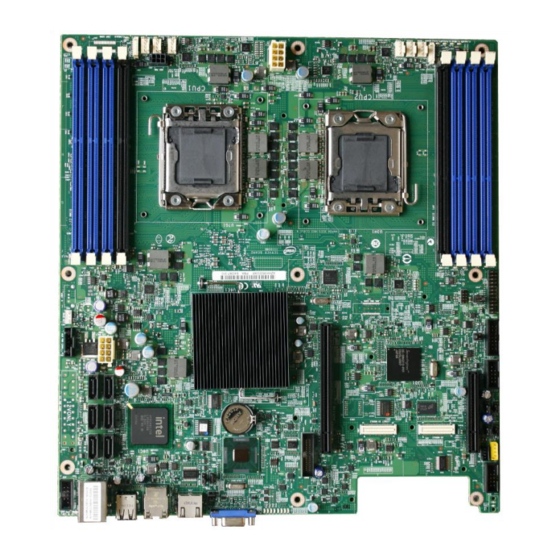
- Page 9 List of Figures ® Figure 1. Intel Server Board S5500WB 12V ................4 Figure 2. Intel Server Board S5500WB SSI ................5 ® Figure 3. Intel Server Board S5500WB Components (both SKUs are shown) ......6 Figure 4. Rear Panel Connector Placement: ................8 Figure 5.
- Page 10 List of Figures Intel® Server Board S5500WB TPS Figure 32. Power Distribution Diagram ..................83 Figure 33. Diagnostic LED Placement Diagram ................ 89 Revision 1.9 Intel order number E53971-008...
- Page 11 Intel® Server Board S5500WB TPS List of Tables List of Tables ® Table 1. Intel Server Board S5500WB Feature Set ..............2 ® Table 2. Intel Server Board S5500WB System Interconnects ........... 7 ® Table 3. Intel Server Board S5500WB Features ..............13 Table 4.
- Page 12 List of Tables Intel® Server Board S5500WB TPS Table 32. SGPIO Header (J1B1) ....................55 Table 33. Front Panel SSI Standard 24-pin Connector Pin-out (J1E2) ........55 Table 34. Power LED Indicator States ..................57 Table 35. System Status LED ....................58 Table 36.
- Page 13 Intel® Server Board S5500WB TPS List of Tables <This page is intentionally left blank.> Revision 1.9 xiii Intel order number E53971-008...
-
Page 15: Introduction
Intel ensures through its own chassis development and testing that when Intel server building blocks are used together, the fully integrated system will meet the intended thermal requirements of these components. It is the... -
Page 16: Server Board Overview
Processor 5500 and 5600 series processors in FC-LGA 1366 Socket B package with up to 95 W Thermal Design Power (TDP) Supports future processor compatibility guidelines ® ® 4.8 GT/s, 5.86 GT/s, and 6.4 GT/s Intel QuickPath Interconnect (Intel QPI) Meets EVRD11.1... - Page 17 Hard Drive Support for six ICH10R SATA II ports Optional support for SW RAID 5 with activation key ® ® Two 10/100/1000 ports provided by Intel 82576 PHYs with Intel I/O Acceleration Technology 2 support Server Management Onboard ServerEngines* LLC Pilot II Controller.
-
Page 18: Intel Server Board S5500Wb Server Board
Server Board Overview Intel® Server Board S5500WB TPS Intel Server Board S5500WB Server Board ® ® The Intel Server Board S5500WB has two board SKUs, such as SSI-compliant and 12-V-only- SKU. The board layouts of the SKUs are shown. ®... -
Page 19: Figure 2. Intel Server Board S5500Wb Ssi
Intel® Server Board S5500WB TPS Server Board Overview Figure 2. Intel Server Board S5500WB SSI Revision 1.9 Intel order number E53971-008... -
Page 20: Server Board Connector And Component Layout
Server Board Overview Intel® Server Board S5500WB TPS Server Board Connector and Component Layout ® Figure 3. Intel Server Board S5500WB Components (both SKUs are shown) Revision 1.9 Intel order number E53971-008... -
Page 21: Table 2. Intel ® Server Board S5500Wb System Interconnects
Intel® Server Board S5500WB TPS Server Board Overview ® Table 2. Intel Server Board S5500WB System Interconnects Description Description ® Dual Intel I/O Expansion Module Processor Socket 1 Connectors PCI Express x16 Gen2 8 Pin CPU Connector Remote Management Module 3... -
Page 22: Board Rear Connector Placement
Status LED RJ-45 Serial port connector RJ-45 GbE/Dual USB connector DB15 Video Dual USB connector Diagnostic LEDs 2.2.2 Server Board Mechanical Drawings ® The following figures are mechanical drawings for the Intel Server Board S5500WB. Revision 1.9 Intel order number E53971-008... -
Page 23: Figure 5. Baseboard And Mounting Holes
Intel® Server Board S5500WB TPS Server Board Overview Figure 5. Baseboard and Mounting holes Revision 1.9 Intel order number E53971-008... -
Page 24: Figure 6. Connector Locations
Server Board Overview Intel® Server Board S5500WB TPS Figure 6. Connector Locations Revision 1.9 Intel order number E53971-008... -
Page 25: Figure 7. Primary Side Height Restrictions
Intel® Server Board S5500WB TPS Server Board Overview Figure 7. Primary Side Height Restrictions Revision 1.9 Intel order number E53971-008... -
Page 26: Figure 8. Secondary Side Height Restrictions
Server Board Overview Intel® Server Board S5500WB TPS Figure 8. Secondary Side Height Restrictions Revision 1.9 Intel order number E53971-008... -
Page 27: Functional Architecture
IPMI 2.0 support Chassis* Reference Reference Power Supply 12 V and 5 VS/B PMBus* 12 V, 5 V, 3.3 V, 5 VSB, PMBus* Note: ® *Referenced Chassis: Chenbro RM13204 Chassis and Intel Server System SR1690WB. Revision 1.9 Intel order number E53971-008... -
Page 28: Functional Block Diagram
Functional Architecture Intel® Server Board S5500WB TPS Functional Block Diagram ® Figure 9. Intel Server Board S5500WB Functional Block Diagram Revision 1.9 Intel order number E53971-008... -
Page 29: Processor Subsystem
5500 series processor is a multi-core processor based on the 45 nm process ® technology. Processor features vary by SKU and include up to two Intel QPI point-to-point links capable of up to 6.4 GT/s, up to 8 MB of shared cache, and an integrated memory controller. -
Page 30: Table 4. Mixed Processor Configurations
Alerts the Integrated BMC about the configuration error. Does not disable the processor. Displays ―0195: Processor 0x Intel(R) QPI speed mismatch‖ message in the Error Manager. If POST Error Pause is disabled in the Setup, continues to boot in a degraded state. -
Page 31: Installing Or Replacing The Processor
Intel® Server Board S5500WB TPS Functional Architecture 3.3.3 Installing or Replacing the Processor 3.3.3.1 Installing the Processor To install a processor, follow these instructions: 1. Turn off all peripheral devices connected to the server. 2. Turn off the server. 3. Disconnect the AC power cord from the server. -
Page 32: Figure 12. Installing Processor
Functional Architecture Intel® Server Board S5500WB TPS Figure 12. Installing processor 9. Lower the load plate and load lever of the ILM cover completely. Note: Make sure the alignment triangle mark and the alignment triangle cutout align correctly. To assist in package orientation and alignment with the socket: A. -
Page 33: Figure 13. Package Installation/Remove Feature
Intel® Server Board S5500WB TPS Functional Architecture Figure 13. Package Installation/Remove Feature 3.3.3.2 Installing the Processor Heatsink(s) CAUTION: The heatsink has Thermal Interface Material (TIM) located on the bottom of it. Use caution when you unpack the heatsink so you do not damage the TIM To install the heatsink, follow these steps: 1. -
Page 34: Qpi)
® ® direction. Each Intel 5500 series and 5600 series processor supports two Intel QPI links, one ® going to the second processor and one going to the Intel 5500 chipset IOH. ® Figure 15. Intel QPI Link Revision 1.9... -
Page 35: Intel ® Quickpath Memory Controller
5500 series and 5600 series processors have an integrated memory controller on its ® package. Each processor produces up to three channels of DDR3 memory. The Intel Memory Controller supports DDR3 800, DDR3 1066, and DDR3 1333 memory technologies. The memory controller supports both Registered DIMMs (RDIMMs) and Unbuffered DIMMs (UDIMMs). -
Page 36: Ecc Support
When 4 GB or more of physical memory is installed (physical memory is the memory installed ® as DDR3 DIMMs), the reserved memory is lost. However, the Intel 5500 Series Chipset provides a feature called high-memory reclaim, which allows the BIOS and operating system to remap the lost physical memory into system memory above 4 GB (the system memory is the memory that can be seen by the processor). -
Page 37: Memory Population Rules
Intel® Server Board S5500WB TPS Functional Architecture The BIOS will always enable high-memory reclaim if it discovers installed physical memory equal to or greater than 4 GB. For the operating system, the reclaimed memory is recoverable only when it supports and enables the PAE feature in the processor. Most operating systems support this feature. -
Page 38: Figure 17. Installing Memory
Functional Architecture Intel® Server Board S5500WB TPS Figure 17. Installing Memory 4. Make sure the clips at either end of the DIMM socket(s) are pushed outward to the open position (see letter ―A‖ in the figure above). 5. Holding the DIMM by the edges, remove it from its anti-static package. -
Page 39: Channel-Independent Mode
Channel mirroring is a RAS feature in which two identical images of memory data are ® maintained, thus providing maximum redundancy. On the Intel 5500 series based Intel server boards, mirroring is achieved across channels. Active channels hold the primary image and the other channels hold the secondary image of the system memory. -
Page 40: Memory Error Led
The Intel 5500 Chipset component is an I/O Hub (IOH). The Intel 5500 Chipset provides a ® connection point between various I/O components and Intel processors using the Intel interface. ® The Intel 5500 Chipset IOH is capable of interfacing with up to 24 PCI Express* lanes, which can be configured in various combinations of x4, x8, x16 and limited x2 and x1 devices. -
Page 41: Management Engine
Virtualization Technology is designed to support multiple software environments sharing the same hardware resources. Each software environment may consist of an operating ® system and applications. You can enable or disable the Intel Virtualization Technology in the BIOS setup. The default behavior is disabled. -
Page 42: Intel 82801Jx I/O Controller Hub (Ich10R)
PECI 2.0 Proxy: SPS offers a means for a BMC without a PECI 2.0 interface to use the ME as a PECI proxy. The BMC on Intel servers already has a PECI 2.0 interface, so this SPS capability is not used. -
Page 43: Usb 2.0 Support
® implementation and provides the ability to use an Intel Embedded Server RAID Technology II ® volume as a boot disk as well as to detect any faults in the Intel Embedded Server RAID Technology II volume(s). 3.7.2 USB 2.0 Support The USB controller functionality integrated into ICH10R provides the server board with an interface for up to 12 USB 2.0 ports. -
Page 44: Network Interface Controller (Nic)
Layer (PHY) ports. The Intel 82576 NIC provides the server board with support for dual LAN ® ports designed for 10/100/1000 Mbps operation. Refer to the Intel 82576 Gigabit Ethernet Controller Datasheet (Document#: 82576) for full details of the NIC feature set. -
Page 45: Mac Address Definition
Intel® Server Board S5500WB TPS Functional Architecture 3.8.1 MAC Address Definition ® The Intel Server Board S5500WB has the following four MAC addresses assigned to it at the Intel factory. NIC 1 MAC address NIC 2 MAC address – Assigned the NIC 1 MAC address +1 ... - Page 46 Functional Architecture Intel® Server Board S5500WB TPS Two 16C550 compatible serial ports Serial IRQ support 16 GPIO ports (shared with Integrated BMC) LPC to SPI Bridge for system BIOS support SMI and PME support ...
-
Page 47: Integrated Bmc Embedded Lan Channel
Intel® Server Board S5500WB TPS Functional Architecture Figure 19. Integrated BMC Hardware 3.9.1 Integrated BMC Embedded LAN Channel The Integrated BMC hardware includes two dedicated 10/100 network interfaces. These interfaces are not shared with the host system. At any time, you can enable only one dedicated interface for management traffic. -
Page 48: Rmm3 Advanced Management Board
Functional Architecture Intel® Server Board S5500WB TPS 3.9.2 RMM3 Advanced Management Board: The RMM3 advanced management board serves two purposes. The first is to give the customer the option to add a dedicated management 100-Mbit LAN interface to the product. -
Page 49: Video Modes
Intel® Server Board S5500WB TPS Functional Architecture 3.12.1 Video Modes The integrated video controller supports all standard VGA modes. The following table shows the 2D modes supported for both CRT and LCD. Table 9. Supported Video Modes 3.12.2 Dual Video The BIOS supports both single-video and dual-video modes. -
Page 50: 3.13 I/O Slots
Functional Architecture Intel® Server Board S5500WB TPS ® The Intel Server Board S5500WB provides a mechanism to support video to the front panel via the use of an internal header. When a monitor is plugged into the front panel video connector, the rear panel video stream is disconnected. -
Page 51: I/O Module Connector
Server Board S5500WB. ® ® The Intel I/O Expansion Module is also required to inform the IOH of the Intel I/O Expansion Module Bus usage, PEWIDTH bit 1 is to be used for this. ® Table 12. Intel I/O Expansion Module Bus PEWIDTH Bits Intel®... -
Page 52: Intel I/O Expansion Modules
I/O Expansion Module controller does not support a single-wide module; it is only used to support a double-wide module. You must mount single-wide modules on ® connector (J3B1) closest to Slot 6, marked Legacy Intel I/O Expansion Module on the ®... - Page 53 Quad port Gigabit Ethernet I/O Expansion Module based on AXX4GBIOMOD2 ® the Intel 82576EB Gigabit Ethernet Controller. AXXIBQDRMOD InfiniBand* I/O Expansion Module Single Port QDR. ® For more information, refer to the I/O modules in the Intel I/O Expansion Modules Hardware Specification. Revision 1.9 Intel order number E53971-008...
-
Page 54: Platform Management Features
Platform Management Features Intel® Server Board S5500WB TPS Platform Management Features This section explains BIOS and firmware (FW) requirements that drive specific hardware implementations of the platform. To a large extent, this is background information. BIOS Feature Overview ® The Intel Server Board S5500WB product uses the AMI Aptio v3.x code base. -
Page 55: Bmc Firmware
Intel® Server Board S5500WB TPS Platform Management Features The Server Engines Pilot II baseboard management controller across Intel’s server product line ® with two different management feature set configurations: Basic and Advanced. The Intel Server Board S5500WB supports both. Basic features include IPMI 2.0 support, remote management, hardware monitoring, event management, event alerting, system event log, asset inventory, console redirection, web interface, and SMASH CLP (basic feature set). -
Page 56: Bmc Advanced Features
AMT or AT) provided by the ME on client platforms. Server Platform Services (SPS) are value-added platform management options that enhance the value of Intel platforms and their component ingredients (CPUs, chipsets, and I/O components). Each service is designed to function independently wherever possible, or Revision 1.9... -
Page 57: Bmc - Management Engine Interaction
L0 and L3 power management states are supported on all PCI Express* slots and embedded end points. 5.5.3 PMBus* ® Power supplies that have PMBus* 1.1 are supported and required to support Intel Dynamic ® ® Power Node Manager. Intel... -
Page 58: I2C\Smbus Architecture Block
Platform Management Features Intel® Server Board S5500WB TPS I2C\SMBUS Architecture Block S5500WB I2C\SMBUS Block Diagram Figure 20. 5.6.1 I2C\SMBUS Device Addresses Table 21 lists the I2C\SMBus addresses of various devices by bus. Table 16. I2C/SMBus Device Address Assignment Main Power... - Page 59 Intel® Server Board S5500WB TPS Platform Management Features Main Power Power Device I2C\SMBus Note Rail Rail Address 3V3SB IBMC I2C\SMBus 5 NIC LAN Link 3V3SB IBMC I2C\SMBus 4 ICH10R SMLINK 0x88 PS FRU 0xAC PS I2C\PSMI 0xB0 Spare 3V3SB IBMC I2C\SMBus 2...
-
Page 60: Configuration Jumpers
Configuration Jumpers Intel® Server Board S5500WB TPS Configuration Jumpers The following table provides a summary and description of configuration, test, and debug ® jumpers on the Intel Server Board S5500WB. The server board has several 3-pin jumper blocks that can be used. -
Page 61: Force Ibmc Update (J1B5)
Intel® Server Board S5500WB TPS Configuration Jumpers Table 17: Server Board Jumpers (J1B5, J1C2, J1C3, J1B4, J6A3, J6A2) Mode of Jumper Name Jumper Position Note Operation J1B5: BMC Force Normal IBMC GPIO[1] is pulled HIGH. Default position. Update jumper Update IBMC GPIO[1] is pulled LOW. -
Page 62: Password Clear (J1C2)
Configuration Jumpers Intel® Server Board S5500WB TPS 6. Perform the BMC firmware update procedure as documented in the README.TXT file included in the given BMC firmware update package. After successful completion of the firmware update process, the firmware update utility may generate an error stating the BMC is still in update mode. -
Page 63: Bios Recovery Mode (J1C3)
Intel® Server Board S5500WB TPS Configuration Jumpers 6.1.3 BIOS Recovery Mode (J1C3) ® The Intel Server Board S5500WB uses BIOS recovery to repair the system BIOS from flash corruption in the main BIOS and Boot Block. This 3-pin jumper is used to reload the BIOS when the image is suspected to be corrupted. -
Page 64: Reset Bios Configuration (J1B4)
Configuration Jumpers Intel® Server Board S5500WB TPS 6.1.4 Reset BIOS Configuration (J1B4) This jumper used to be the CMOS Clear jumper. Since the previous generation, the BIOS has moved CMOS data to the NVRAM region of the BIOS flash. The BIOS checks during boot to determine if the data in the NVRAM needs to be set to default. -
Page 65: Me Firmware Force Update (J7A2)
Intel® Server Board S5500WB TPS Configuration Jumpers 6.1.6 ME Firmware Force Update (J7A2) Pins ME Firmware Update Mode Disabled (Default) Enabled The ME firmware consists of two operational images and a recovery image. During boot, the recovery loader is started first and it tries to load the active firmware image by running the loader of this image. -
Page 66: Connector/Header Locations And Pin-Out
Connector/Header Locations and Pin-out Intel® Server Board S5500WB TPS Connector/Header Locations and Pin-out Power Connectors Table 23. SSI SKU 24-pin 2x12 Connector (J9B3) Signal Name Signal Name +3.3V +3.3V +3.3V -12V PS_ON PWR_GD SB5V +12V +12V +3.3V Table 24. CPU 12V Power 2x4 Connector (J5K1) -
Page 67: Table 26. 12-V Only 2X4 Connector (Replaces Epsd12V 2X12 Connector) (J9D2)
Intel® Server Board S5500WB TPS Connector/Header Locations and Pin-out Table 26. 12-V only 2x4 Connector (replaces EPSD12V 2x12 connector) (J9D2) Signal Name +12V +12V +12V +12V Table 27. 12-V Only Power Control (replaces the 1x5 power control) (J9D1) (FOXCONN ELECTRONICS INC HF1107V-P1 or TYCO ELECTRONICS CORPORATION 5-104809-6) -
Page 68: System Management Headers
Intel Remote Management Module 3. There is no support for third-party management cards on this server board. ® ® Note: This connector is not compatible with the Intel Remote Management Module (Intel ® ® RMM) or the Intel Remote Management Module 2 (Intel RMM2). -
Page 69: Hard Drive Activity (Input) Led Header
Intel® Server Board S5500WB TPS Connector/Header Locations and Pin-out 7.2.3 Hard Drive Activity (Input) LED Header Table 47. SATA HDD Activity (Input) LED Header (J1D2) Description LED_HD_ACTIVE_L 7.2.4 IPMB Header Table 31. IPMB Header 4-pin (J1B2) Signal Name Description SMB_IPMB_5VSB_DAT... -
Page 70: Power Button
Connector/Header Locations and Pin-out Intel® Server Board S5500WB TPS Combined system BIOS and the Integrated BMC support provide the functionality of the various supported control panel buttons and LEDs. The following sections describe the supported functionality of each control panel feature. -
Page 71: Power Led
Intel® Server Board S5500WB TPS Connector/Header Locations and Pin-out 7.3.5 Power LED The green power LED is active when the system DC power is on. The power LED is controlled by the BIOS. The power LED reflects a combination of the state of system (DC) power and the system ACPI state. -
Page 72: Table 35. System Status Led
Connector/Header Locations and Pin-out Intel® Server Board S5500WB TPS Table 35. System Status LED Color State System Status Description Green Solid on System ready Green ~1 Hz blink Degraded BIOS detected Unable to use all of the installed memory (more than one DIMM installed).1... -
Page 73: Chassis Id Led
Intel® Server Board S5500WB TPS Connector/Header Locations and Pin-out 7.3.7 Chassis ID LED The chassis ID LED provides a visual indication of a system being serviced. The state of the chassis ID LED is affected by the following: Toggled by the chassis ID button ... -
Page 74: Table 38. Slot 1 Pci Express* X8 Connector (J1B3)
Connector/Header Locations and Pin-out Intel® Server Board S5500WB TPS Side Side Side Side PCI Express* Signal PCI Express* Signal PCI Express* Signal PCI Express* Signal REFCLK+ PETxN9 PETxP0 REFCLK- PERxP9 PETxN0 PERxN9 PERxP0 PETxP10 PRSNT2# PERxN0 PETxN10 PERxP10 PETxP1 RSVD... -
Page 75: Vga Connectors
Intel® Server Board S5500WB TPS Connector/Header Locations and Pin-out Pin-Side B PCI Express* Spec Signal Description Pin-Side A PCI Express* Spec Description Signal REFCLK1+ PETp(0) REFCLK1+ PETn(0) PERp(0) Reserved PERn(0) 1X end PETp(1) Reserved PETn(1) PERp(1) PERn(1) PETp(2) PETn(2) PERp(2) -
Page 76: Nic Connectors
Connector/Header Locations and Pin-out Intel® Server Board S5500WB TPS Signal Name Description Ground TP_VID_CONN_B9 No connection Ground TP_VID_CONN_B11 No connection V_IO_DDCDAT DDCDAT V_IO_HSYNC_CONN HSYNC (horizontal sync) V_IO_VSYNC_CONN VSYNC (vertical sync) V_IO_DDCCLK DDCCLK The following table details the pin-out definition of the internal VGA connector (J1D1): Table 40. -
Page 77: Table 41. Rj-45 10/100/1000 Nic Connector Pin-Out (J8A2, J9A1)
Intel® Server Board S5500WB TPS Connector/Header Locations and Pin-out Table 41. RJ-45 10/100/1000 NIC Connector Pin-out (J8A2, J9A1) Revision 1.9 Intel order number E53971-008... -
Page 78: Sata Connectors
I/O Expansion Modules for use on this server board. For more ® ® information on the supported Intel I/O Expansion Modules, refer to the Intel Server Board IO ® Module Hardware Specification. The following table details the pin-out of the Intel Expansion Module connectors. Revision 1.9 Intel order number E53971-008... -
Page 79: Table 43. 50-Pin Intel ® I/O Expansion Module Connector Pin-Out (J2B1, J3B1)
Intel® Server Board S5500WB TPS Connector/Header Locations and Pin-out ® Table 43. 50-pin Intel I/O Expansion Module Connector Pin-out (J2B1, J3B1) Revision 1.9 Intel order number E53971-008... -
Page 80: Serial Port Connectors
Connector/Header Locations and Pin-out Intel® Server Board S5500WB TPS 7.4.6 Serial Port Connectors The server board provides one external RJ-45 Serial A port (J7A1) and one internal 9-pin serial B header (J1A2). The following tables define the pin-outs. Table 44. External RJ-45 Serial Port A (COM1) (J7A1) -
Page 81: Fan Headers
Intel® Server Board S5500WB TPS Connector/Header Locations and Pin-out Table 48. Low-Profile Internal USB Connector (J1E3) Signal Name Signal Name USB_N USB_P Key Pin LED# Fan Headers The server board provides six SSI-compliant 4-pin fan headers and two 8-pin fan headers to be used for CPU, and IO cooling. -
Page 82: Intel Light-Guided Diagnostics
Intel Light-Guided Diagnostics Intel® Server Board S5500WB TPS ® Intel Light-Guided Diagnostics ® The server boards have several onboard diagnostic LEDs to assist in troubleshooting board- level issues. This section provides a description the location and function of each LED on the server board. -
Page 83: Fan Fault Leds
Intel® Server Board S5500WB TPS Intel Light-Guided Diagnostics ® Fan Fault LEDs Fan fault LEDs are present for the six fans and are located near each CPU fan header. FLTMEM2R FLTCPU1 FLTMEM2 FLTCPU1A FLTCPU2A FLTMEM1 FLTCPU2 FLTMEM1R Figure 23. Fan Fault LED Locations System Status LED The server board provides LED for system status. -
Page 84: Figure 24. System Status Led Location
Intel Light-Guided Diagnostics Intel® Server Board S5500WB TPS ® Figure 24. System Status LED Location The bi-color System Status LED operates as follows: Revision 1.9 Intel order number E53971-008... -
Page 85: Table 51. System Status Led
Intel® Server Board S5500WB TPS Intel Light-Guided Diagnostics ® Table 51. System Status LED Color State System Status Description Green Solid on System ready System degraded: BIOS detected Unable to use all of the installed memory (more than one DIMM installed).1 In a mirrored configuration, when memory mirroring takes place and system loses memory redundancy. - Page 86 Intel Light-Guided Diagnostics Intel® Server Board S5500WB TPS ® Color State System Status Description Fatal alarm – system has failed or shut down: BIOS Detected DIMM failure when there is one DIMM present and no good memory is present.1 Run-time memory uncorrectable error in non-redundant mode.1 CPU configuration error (for instance, processor stepping mismatch).
-
Page 87: Dimm Fault Leds
Intel® Server Board S5500WB TPS Intel Light-Guided Diagnostics ® DIMM Fault LEDs Each DIMM slot has a DIMM Fault LED near the DIMM slot. Figure 25. DIMM Fault LEDs Locations FLT_F FLT_A2 FLT_E FLT_A1 FLT_D1 FLT_B FLT_D2 FLT_C Revision 1.9... -
Page 88: Post Code Diagnostic Leds
Intel Light-Guided Diagnostics Intel® Server Board S5500WB TPS ® POST Code Diagnostic LEDs Eight amber POST code diagnostic LEDs are located on the back edge of the server board in the rear I/O area of the server board by the VGA connector. -
Page 89: Front Panel Support
Intel® Server Board S5500WB TPS Intel Light-Guided Diagnostics ® Front Panel Support ® The Intel Server Board S5500WB supports SSI standard front panel boards. The front panel support is provided by a SSI compatible 2x12-pin signal connector. The front panel connector supports the following diagnostic LEDs. -
Page 90: Design And Environmental Specifications
Design and Environmental Specifications Intel® Server Board S5500WB TPS Design and Environmental Specifications Fan Speed Control Thermal Management Fan speed control supports the following thermal sensors: Discrete board level digital thermal sensor TMP75 Front panel Temp Sensor (if present) ... -
Page 91: Figure 28: Location Of Fan Connectors
Intel® Server Board S5500WB TPS Design and Environmental Specifications The following tables show a basic location of the fan connectors on the board. The first line is the silk screen name of the connector; the second is the PWM signal name; the third is the Tach #;... -
Page 92: Thermal Sensors
Design and Environmental Specifications Intel® Server Board S5500WB TPS Table 54. Fan Connector Location & Detail CPU 2 Memory 2 FAN_CPU2 FAN_CPU2A FAN_MEM2 FAN_MEM2R PWM_CPU0 PWM_CPU0 PWM_MEM0 PWM_MEM0 Tach 3 Tach 7 Tach 4 Tach 4 & 8 J3E1 J2J2... -
Page 93: Memory Temperature Sensor
9.2.2 Memory Temperature Sensor ® DDR3 cooling requires thermal throttling to protect memory from overheating. The Intel Server Board S5500WB supports both DDR3 UDIMM and DDR3 RDIMM. SPD temperature sensor on DIMM is anticipated to be available on all DDR3 RDIMM but not for non-ECC UDIMM, so open loop thermal throttling and closed loop thermal throttling are supported. -
Page 94: Heatsinks
Design and Environmental Specifications Intel® Server Board S5500WB TPS Figure 30: Temp Sensor Location Location Description U4K3 Temp Sensor - TMP75 Heatsinks ® The Intel Server Board S5500WB system cooling solutions rely on heatsinks for CPU cooling. Chipset and or voltage regulator heatsinks are compatible with the 1U usage. -
Page 95: Unified Retention System Support
Philips* screwdriver to attach to the unified backplate assembly. See the following figure for the stacking order of the URS components. The ILM and unified backplate are removable, allowing for the use of non-Intel heatsink retention solutions. -
Page 96: Errors
Design and Environmental Specifications Intel® Server Board S5500WB TPS Errors This section outlines how errors are routed in the hardware to ensure appropriate FW action (logging, fan control, system management, and so forth) is taken when an event occurs. 9.4.1 PROCHOT# PROCHOT# is a bi-directional signal. -
Page 97: 10. Power Subsystem
Intel® Server Board S5500WB TPS Power Subsystem 10. Power Subsystem 10.1 Server Board Power Distribution Figure 32. Power Distribution Diagram 10.2 Power Supply Compatibility ® The Intel Server Board S5500WB is offered in two models: SSI SKU: This version of the server board is designed to work with an ―off-the-shelf‖... -
Page 98: 10.3 Power Sequencing And Reset Distribution
Power Subsystem Intel® Server Board S5500WB TPS The SSI uses the standard 24-pin and 8-pin power headers along with the 5pin Control connector. The 12-V only uses two 8-pin power headers, a 7-pin control header and a 6 pin HDD power connector. For maximum rack server efficiency, a DC 12-V only power supply is recommended. -
Page 99: 11. Regulatory And Certification Information
Intel® Server Board S5500WB TPS Regulatory and Certification Information 11. Regulatory and Certification Information 11.1 Product Regulation Requirements Intended Application – This product was evaluated as Information Technology Equipment (ITE), which may be installed in offices, schools, computer rooms, and similar commercial type locations. -
Page 100: 11.2 Product Regulatory Compliance Markings
Belarus – Listed on one System Certification (Belarus) KCC Certification (Korea) Ecology Declaration (International) 11.2 Product Regulatory Compliance Markings This Intel Server Board bears the following regulatory marks: Table 55: Product Regulatory Compliance Markings Regulatory Compliance Country Marking UL Mark USA/Canada... -
Page 101: Ices-003 (Canada)
Intel® Server Board S5500WB TPS Regulatory and Certification Information For questions related to the EMC performance of this product, contact: Intel Corporation 5200 N.E. Elam Young Parkway Hillsboro, OR 97124-6497 1-800-628-8686 This equipment has been tested and found to comply with the limits for a Class A digital device, pursuant to Part 15 of the FCC Rules. -
Page 102: Europe (Ce Declaration Of Conformity)
English translation of the notice above: 1. Type of Equipment (Model Name): On Certification and Product 2. Certification No.: On KCC certificate. Obtain certificate from local Intel representative 3. Name of Certification Recipient: Intel Corporation 4. Date of Manufacturer: Refer to date code on product 5. -
Page 103: Appendix A: Post Code Led Decoder
Intel® Server Board S5500WB TPS Appendix A: POST Code LED Decoder Appendix A: POST Code LED Decoder During the system boot process, the BIOS executes several platform configuration processes, each of which is assigned a specific hex POST code number. As each configuration routine is started, the BIOS displays the POST code on the POST code diagnostic LEDs found on the back edge of the server board. -
Page 104: Table 56. Post Progress Code Led Example
Appendix A: POST Code LED Decoder Intel® Server Board S5500WB TPS In the following example, the BIOS sends a value of ACh to the diagnostic LED decoder. The LEDs are decoded as follows: Table 56. POST Progress Code LED Example... -
Page 105: Table 57. Diagnostic Led Post Code Decoder
Intel® Server Board S5500WB TPS Appendix A: POST Code LED Decoder Table 57. Diagnostic LED POST Code Decoder Diagnostic LED Decoder 1 = On, 0=Off Checkpoint Upper Nibble Lower Nibble Description Host Processor 0x10h Power-on initialization of the host processor (bootstrap processor) - Page 106 Appendix A: POST Code LED Decoder Intel® Server Board S5500WB TPS QuickPath Interconnect (QPI) 0xA0h QPI Initialization 0xA1h QPI Initialization 0xA2h QPI Initialization 0xA3h QPI Initialization 0xA4h QPI Initialization 0xA5h QPI Initialization 0xA6h QPI Initialization 0xA7h QPI Initialization 0xA8h QPI Initialization...
- Page 107 Intel® Server Board S5500WB TPS Appendix A: POST Code LED Decoder 0x56h Initializing USB host controllers 0x57h Detecting USB devices 0x58h Resetting USB bus 0x59h Reserved for USB devices ATA/ATAPI/SATA 0x5Ah Resetting SATA bus and all devices 0x5Bh Detecting the presence of ATA device...
- Page 108 Appendix A: POST Code LED Decoder Intel® Server Board S5500WB TPS Fixed Media 0xB0h Resetting fixed media device 0xB1h Disabling fixed media device Detecting presence of a fixed media device (SATA hard drive 0xB2h detection, and so forth) 0xB3h Enabling / configuring a fixed media device...
- Page 109 Intel® Server Board S5500WB TPS Appendix A: POST Code LED Decoder Pre-EFI Initialization Module (PEIM) / Recovery 0x30h Crisis recovery initiated because of a user request 0x31h Crisis recovery initiated by software (corrupt flash) 0x34h Loading crisis recovery capsule 0x35h...
-
Page 110: Appendix B: Video Post Code Errors
Processor 0x cache size mismatch detected. Fatal 0193 Processor 0x stepping mismatch. Minor 0194 Processor 0x family mismatch detected. Fatal 0195 Processor 0x Intel(R) QPI speed mismatch. Major 0196 Processor 0x model mismatch. Fatal 0197 Processor 0x speeds mismatched. Fatal 0198 Processor 0x family is not supported. - Page 111 Intel® Server Board S5500WB TPS Appendix B: Video POST Code Errors Error Code Error Message Response 8160 Processor 01 unable to apply microcode update Major 8161 Processor 02 unable to apply microcode update Major 8180 Processor 0x microcode update not found.
- Page 112 Appendix B: Video POST Code Errors Intel® Server Board S5500WB TPS Error Code Error Message Response 8568 DIMM_E1 Component encountered a Serial Presence Detection (SPD) fail error. Major 8569 DIMM_E2 Component encountered a Serial Presence Detection (SPD) fail error. Major 856A DIMM_F1 Component encountered a Serial Presence Detection (SPD) fail error.
- Page 113 Intel® Server Board S5500WB TPS Appendix B: Video POST Code Errors Error Code Error Message Response 96E7 SMM driver component encountered a illegal software state error. Fatal 0xA000 TPM device not detected. Minor 0xA001 TPM device missing or not responding.
-
Page 114: Glossary
Glossary Intel® Server Board S5500WB TPS Glossary This appendix contains important terms used in the preceding chapters. For ease of use, numeric entries are listed first (for example, ―82460GX‖) with alpha entries following (for example, ―AGP 4x‖). Acronyms are then entered in their respective place, with non-acronyms following. - Page 115 Intel® Server Board S5500WB TPS Glossary Term Definition Host Physical Address Hertz (1 cycle / second) Inter-Integrated Circuit Bus ® Intel Architecture Input Buffer I/O Controller Hub IC MB Intelligent Chassis Management Bus I/O and Firmware Bridge Independent Loading Mechanism...
- Page 116 Glossary Intel® Server Board S5500WB TPS Term Definition QuickPath Interconnect Random Access Memory RASUM Reliability, Availability, Serviceability, Usability, and Manageability RISC Reduced Instruction Set Computing Read Only Memory Real-Time Clock (Component of ICH peripheral chip on the server board) RMM3...
-
Page 117: Reference Documents
Server System Integrated Baseboard Management Controller Core External Product Specification, 2007. Intel Corporation. ® Intel Thurley Server Platform Services IPMI Commands Specification, 2007. Intel Corporation. Intelligent Platform Management Bus Communications Protocol Specification, Version 1.0, 1998. Intel Corporation, Hewlett-Packard Company, NEC Corporation, Dell Computer Corporation.
Need help?
Do you have a question about the S5500WB12V and is the answer not in the manual?
Questions and answers