
Subscribe to Our Youtube Channel
Related Manuals for Intel S5000XSL


Summary of Contents for Intel S5000XSL
- Page 1 Intel® Server Boards S5000PSL and S5000XSL Technical Product Specification Intel order number: D41763-003 Revision 1.2 September 2006 Enterprise Platforms and Services Division – Marketing Revision 1.2 Intel order number: D41763-003...
-
Page 2: Revision History
Terms and Conditions of Sale for such products, Intel assumes no liability whatsoever, and Intel disclaims any express or implied warranty, relating to sale and / or use of Intel products including liability or warranties relating to fitness for a particular purpose, merchantability, or infringement of any patent, copyright or other intellectual property right. -
Page 3: Table Of Contents
Network Interface Controller (NIC) ... 48 ® 3.5.1 Intel I/O Acceleration Technolgy ... 49 3.5.2 MAC Address Definition... 49 Super I/O ... 49 3.6.1 Serial Ports ... 50 Intel® Server Boards S5000PSL and S5000XSL TPS Intel order number: D41763-003 Revision 1.2... - Page 4 Intel® Server Boards S5000PSL and S5000XSL TPS 3.6.2 Floppy Disk Controller ... 50 3.6.3 Keyboard and Mouse Support ... 50 3.6.4 Wake-up Control... 50 3.6.5 System Health Support... 50 4. Platform Management... 51 5. Connector / Header Locations and Pin-outs... 53 Board Connector Information...
- Page 5 DIMM Fault LEDs ... 76 Processor Fault LEDs... 77 Post Code Diagnostic LEDs ... 78 8. Design and Environmental Specifications... 79 Server Boards S5000PSL and S5000XSL Design Specifications ... 79 Server Board Power Requirements ... 80 8.2.1 Processor Power Support... 81 Power Supply Output Requirements ...
- Page 6 Intel® Server Boards S5000PSL and S5000XSL TPS Table of Contents Appendix C: POST Code Diagnostic LED Decoder ... 109 Appendix D: POST Code Errors ... 114 ® Appendix E: Supported Intel Server Chassis ... 117 Glossary... 118 Reference Documents ... 121 Revision 1.2...
- Page 7 List of Figures Intel® Server Boards S5000PSL and S5000XSL TPS List of Figures Figure 1. Server Board Photograph ... 17 Figure 2. Major Board Components... 19 Figure 3. Mounting Hole Positions ... 20 Figure 4. Component Positions... 21 Figure 5. Restricted Areas on Side 1 ... 22 Figure 6.
- Page 8 Intel® Server Boards S5000PSL and S5000XSL TPS List of Tables List of Tables Table 1. Server Board Features... 14 Table 2. Processor Support Matrix ... 29 Table 3. I C Addresses for Memory Module SMB ... 33 Table 4. Maximum Eight-DIMM System Memory Configruation – x8 Single Rank ... 34 Table 5.
- Page 9 List of Tables Intel® Server Boards S5000PSL and S5000XSL TPS Table 33. SSI 4-pin Fan Header Pin-out (J9J1, J5J1, J9B3, J9B4)... 66 Table 34. SSI 6-pin Fan Header Pin-out (J3H1, J3H2, J3H3, J3H4)... 66 Table 35. Server Board Jumpers (J1C3, J1D1, J1D2, J1E3) ... 68 Table 36.
- Page 10 Intel® Server Boards S5000PSL and S5000XSL TPS List of Tables This page intentionally left blank Revision 1.2 Intel order number: D41763-003...
-
Page 11: Introduction
Intel Corporation server boards support add-in peripherals and contain a number of high-density VLSI and power delivery components that need adequate airflow to cool. Intel ensures through its own chassis development and testing that when Intel server Intel® Server Boards S5000PSL and S5000XSL TPS ®... - Page 12 Intel Corporation cannot be held responsible if components fail or the server board does not operate correctly when used outside any of their published operating or non-operating limits.
-
Page 13: Server Board Overview
Server Board Overview Server Board Overview ® The Intel Server Boards S5000PSL and S5000XSL are monolithic printed circuit boards with features that support the pedestal server markets. Server Board Feature Set Feature Processors Socket J (771-pin LGA sockets) supporting one or two Dual-Core Intel processors 5000 sequence, with system bus speeds of 667 MHz, 1066 MHz, and 1333 MHz. - Page 14 Intel® Server Boards S5000PSL and S5000XSL TPS Feature On-board External connections: Connectors/Headers Stacked PS/2* ports for keyboard and mouse Stacked video / DB9 serial port A connector Two RJ45 / 2xUSB connectors for 10 / 100 / 1000 Mb and USB 2.0 support...
- Page 15 Server Board Overview Feature Fans Support for Two processor fans Four front hot-swap fans Two rear system fans ® Server Management Support for Intel System Management Software Intel® Server Boards S5000PSL and S5000XSL TPS Description Intel order number: D41763-003 Revision 1.2...
-
Page 16: Server Board Layout
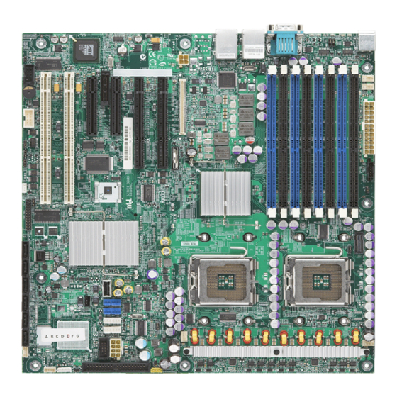
Intel® Server Boards S5000PSL and S5000XSL TPS List of Tables Server Board Layout Figure 1. Server Board Photograph Revision 1.2 Intel order number: D41763-003... -
Page 17: Server Board Connector And Component Layout
The following figure shows the board layout of the server board. Each connector and major component is identified by a letter. A table of component descriptions follows the figure. Intel order number: D41763-003 Intel® Server Boards S5000PSL and S5000XSL TPS AF000247 Revision 1.2... -
Page 18: Figure 2. Major Board Components
Intel® Server Boards S5000PSL and S5000XSL TPS A. PCI-X 64-bit, 100-MHz slot 1 Q. DIMM sockets B. PCI-X 64-bit, 133-/100-MHz slot 2 R. Processor 1 socket C. PCI Express* x4 / x8 slot 3 S. Processor 2 socket D. Advanced Server Management T. -
Page 19: Server Board Mechanical Drawings
Server Board Overview Intel® Server Boards S5000PSL and S5000XSL TPS 2.2.2 Server Board Mechanical Drawings Figure 3. Mounting Hole Positions Revision 1.2 Intel order number: D41763-003... -
Page 20: Figure 4. Component Positions
Intel® Server Boards S5000PSL and S5000XSL TPS List of Tables Figure 4. Component Positions Revision 1.2 Intel order number: D41763-003... -
Page 21: Figure 5. Restricted Areas On Side 1
11.870 311.66 12.270 322.40 12.693 326.57 12.857 330.20 13.000 5.33 0.210 7.92 0.312 16.05 0.632 Intel® Server Boards S5000PSL and S5000XSL TPS 304.80 12.000 11.20 0.441 116.000 60.100 4.5669 2.3661 20.32 0.800 IMM3 COMPONENT HEIGHT 3.6 MM 72.800 2.8661 60.96 2.400... -
Page 22: Figure 6. Restricted Areas On Side 2
Intel® Server Boards S5000PSL and S5000XSL TPS 7.620 0.3000 20.320 0.8000 11 PLCS 5.08 0.200 14.730 0.5799 .100 [2.54<<] MAX COMPONENT HEIGHT IN THESE ZONES 96.52 3.800 57.15 2.250 12.07 0.475 7.62 0.300 17.78 0.700 Revision 1.2 List of Tables LIMITED COMPONENT HEIGHT 2X 3.120... -
Page 23: Figure 7. Restricted Areas On Side 2, "Detail B
Server Board Overview 3X 4.00 3X 10.13 0.399 5.00 5.00 0.197 0.197 0.157 Figure 7. Restricted Areas on Side 2, “Detail B” Intel order number: D41763-003 Intel® Server Boards S5000PSL and S5000XSL TPS 3X 3.00 0.118 CHASSIS ID PADS Revision 1.2... -
Page 24: Figure 8. Cpu And Memory Duct Keepout
Intel® Server Boards S5000PSL and S5000XSL TPS 10.160 [0.4000] 0.000 [0.0000] SUPPORT AREA, NO COMPONENT ALLOWED 15.0mm COMPONENT HEIGHT LIMIT DEFINED BY DUCT DETAIL 9.0 mm COMPONENT HEIGHT LIMIT DEFINED BY DUCT DETAIL 27.0 mm COMPONENT HEIGHT LIMIT DEFINED BY DUCT DETAIL 13.0 mm COMPONENT HEIGHT... -
Page 25: Server Board Atx I/O Layout
E. NIC port 1 (1 Gb) F. USB port 2 (top), 3 (bottom) G. NIC port 2 (1 Gb) H. USB port 0 (top), 1 (bottom) Figure 9. ATX I/O Layout Intel order number: D41763-003 Intel® Server Boards S5000PSL and S5000XSL TPS AF000222 Revision 1.2... -
Page 26: Functional Architecture
Server Boards S5000PSL and S5000XSL are based on the Intel S5000P and S5000X ® ® chipsets respectively. These chipsets are designed for systems that use the Intel Xeon processor with system bus speeds of 667 MHz, 1066 MHz, and 1333 MHz. -
Page 27: Figure 10. Functional Block Diagram
Server Board Overview Intel® Server Boards S5000PSL and S5000XSL TPS Figure 10. Functional Block Diagram Revision 1.2 Intel order number: D41763-003... -
Page 28: Intel ® 5000P / 5000X Memory Controller Hub (Mch)
This section provides a high-level overview of some of these core functions as they pertain to this server board. Additional information can be obtained from the Intel S5000 Server Board Family Datasheet and the Intel 5000 Series Chipset Memory Controller Hub Datasheet. - Page 29 Common Enabling Kit (CEK) Design Support The server board complies with Intel’s Common Enabling Kit (CEK) processor mounting and heatsink retention solution. The server board ships with a CEK spring snapped onto the underside of the server board, beneath each processor socket. The heatsink attaches to the CEK, over the top of the processor and the thermal interface material (TIM).
-
Page 30: Figure 11. Cek Processor Mounting
Intel® Server Boards S5000PSL and S5000XSL TPS List of Tables Note: The processor heat sink and CEK spring shown in the following diagram are for reference purposes only. The actual processor heat sink and CEK solutions compatible with this generation server board may be of a different design. -
Page 31: Memory Sub-System
On the Intel Server Boards S5000PSL and S5000XSL, a pair of channels becomes a branch where Branch 0 consists of channels A and B, and Branch 1 consists of channels C and D. FBD memory channels are organized into two branches for support of RAID 1 (mirroring). -
Page 32: Table 3. I 2 C Addresses For Memory Module Smb
Intel® Server Boards S5000PSL and S5000XSL TPS To boot the system, the system BIOS on the server board uses a dedicated I the MCH memory registers. The following table provides the I 3.1.3.1 Memory RASUM Features The MCH supports several memory RASUM (Reliability, Availability, Serviceability, Usability, and Manageability) features. These ®... -
Page 33: Table 4. Maximum Eight-Dimm System Memory Configruation - X8 Single Rank
512 Mb 1024 Mb 2048 Mb Note: Only fully buffered DDR2 DIMMs (FBDIMMs) are supported on this server board. See the Intel S5000PSL/S5000XSL Tested Memory List for a list of supported memory for this server board. 3.1.3.3 DIMM Population Rules and Supported DIMM Configurations DIMM population rules depend on the operating mode of the memory controller, which is determined by the number of DIMMs installed. - Page 34 For example, a valid mixed DIMM configuration may have 512MB DIMMs installed in DIMM Slots A1 & B1, and 1GB DIMMs installed in DIMM slots C1 & D1. Intel supported DIMM configurations for this server board are shown in the following table. Supported and Validated configuration : Slot is populated...
- Page 35 DIMM configuration will perform better than a two DIMM configuration and should be installed in DIMM Slots A1, B1, C1, and D1. An eight DIMM configuration will perform better then a six DIMM configuration. Although mixed DIMM capacities between channels is supported, Intel does not validate DIMMs in mixed DIMM configurations. Intel® Server Boards S5000PSL and S5000XSL TPS Intel order number: D41763-003 Revision 1.2...
-
Page 36: Figure 13. Minimum Two Dimm Memory Configuration
Branch 1 Figure 13. Minimum Two DIMM Memory Configuration Note: The server board supports single DIMM mode operation. Intel will only validate and support this configuration with a single 512 MB x8 FBDIMM installed in DIMM socket A1. Revision 1.2... -
Page 37: Figure 14. Recommended Four Dimm Configuration
DIMM configuration that is recommended because it allows both branches to operate independently and simultaneously. FBD bandwidth is doubled when both branches operate in parallel. Intel® Server Boards S5000PSL and S5000XSL TPS Channel B Channel A... - Page 38 Intel® Server Boards S5000PSL and S5000XSL TPS 3.1.3.4.1 Mirrored Mode Memory Configuration When operating in mirrored mode, both branches operate in lock step. In mirrored mode, branch 1 contains a replicate copy of the data in branch 0. The minimum DIMM configuration to support memory mirroring is four DIMMs, populated as shown in Figure 14, above.
-
Page 39: Figure 15. Single Branch Mode Sparing Dimm Configuration
Sparing should be enabled in BIOS setup. The BIOS will configure Rank Sparing Mode. The larger of the pairs {DIMM_A1, DIMM_B1} and {DIMM_A2, DIMM_B2} will be selected as the spare pair unit. Intel® Server Boards S5000PSL and S5000XSL TPS DIMM_B2 DIMM_C2 DIMM_B1... -
Page 40: Snoop Filter (5000X Mch Only)
Intel® Server Boards S5000PSL and S5000XSL TPS 3.1.3.4.2.2 Dual Branch Mode Sparing Dual branch mode sparing requires that all eight DIMM sockets be populated and must comply with the following population rules. DIMM_A1 and DIMM_B1 must be identical in organization, size and speed. -
Page 41: Pci Sub-System
General purpose I/O This section describes the function of most of the listed features as they pertain to these server boards. For more detail information, see the Intel S5000 Server Board Family Datasheet or the Intel 631xESB/632xESB I/O Controller Hub Datasheet. - Page 42 Intel® Server Boards S5000PSL and S5000XSL TPS 3.2.1.1 PCI32: 32-bit, 33-MHz PCI Sub-system All 32-bit, 33-MHz PCI I/O is directed through the ESB2-E ICH6. The 32-bit, 33-MHz PCI segment created by the ESB2-E-ICH6 is known as the PCI32 segment. The PCI32 segment...
-
Page 43: Serial Ata Support
See Figure 2 Major Board Components for the location of Intel RAID Activation Key connector location. Note: Availability of the Intel RAID Activation Key to support software RAID 5 will be deferred until after product launch of this server board. -
Page 44: Parallel Ata (Pata) Support
Embedded Server RAID Technology implementation and provides the ® ability for an Intel Embedded Server RAID Technology volume to be used as a boot disk as well as to detect any faults in the Intel ® to the Intel RAID controller. - Page 45 Design and Environmental Specifications Intel® Server Boards S5000PSL and S5000XSL TPS The SVGA sub-system supports a variety of modes, up to 1024 x 768 resolution in 8 / 16 / 32 bpp modes under 2D. It also supports both CRT and LCD monitors up to a 100 Hz vertical refresh rate.
-
Page 46: Video Modes
Intel® Server Boards S5000PSL and S5000XSL TPS 3.3.1 Video Modes The ATI* ES1000 chip supports all standard IBM* VGA modes. The following table shows the 2D modes supported for both CRT and LCD. 2D Mode Refresh Rate (Hz) 640x480 60, 72, 75, 85, 90,... -
Page 47: Sas Controller
LAN ports designed for 10/100/1000 Mbps operation. The 82563EB device is based upon proven PHY technology integrated into Intel’s gigabit Ethernet controllers. The physical layer circuitry provides a standard IEEE 802.3 Ethernet interface for 1000BASE-T, 100BASE-TX, and 10BASE-T applications (802.3, 802.3u, and... -
Page 48: Intel ® I/O Acceleration Technolgy
® Each Intel Server Board S5000PSL / S5000XSL has four MAC addresses assigned to it at the Intel factory. During the manufacturing process, each server board will have a white MAC address sticker placed on the board. The sticker will display the MAC address in both bar code and alpha numeric formats. -
Page 49: Serial Ports
The super I/O provides PMW fan control to the system fans, monitors tach and presence signals for the system fans and monitors server board and front panel temperature. Intel® Server Boards S5000PSL and S5000XSL TPS Table 9. Serial B Header Pin-out... -
Page 50: Platform Management
Server Management Bus (SMBUS) architecture used on this server board. See Appendix B for on-board sensor data. ® For more detailed platform management information, see the Intel S5000 Server Board Family Datasheet. Revision 1.2... -
Page 51: Figure 16. Smbus Block Diagram
Design and Env ironmental Specifications Intel® Server Boards S5000PSL and S5000XSL TPS Figure 16. SMBUS Block Diagram Revision 1.2 Intel order number: D41763-003... -
Page 52: Connector / Header Locations And Pin-Outs
Intel® Server Boards S5000PSL and S5000XSL TPS Connector / Header Locations and Pin-outs Board Connector Information The following section provides detailed information regarding all connectors, headers and jumpers on the server board. Table 10. Board Connector Matrix lists all connector types available on the board and the corresponding reference designators printed on the silkscreen. -
Page 53: Power Connectors
Table 11. Power Connector Pin-out (J9B5) Signal +3.3 Vdc +3.3 Vdc +5 Vdc +5 Vdc PWR_OK 5 VSB +12 Vdc +12 Vdc +3.3 Vdc Intel® Server Boards S5000PSL and S5000XSL TPS Reference Designators Color Signal Orange +3.3 Vdc Orange -12 Vdc Black PS_ON# Black... -
Page 54: Table 12. 12 V Power Connector Pin-Out (J3J2)
Intel® Server Boards S5000PSL and S5000XSL TPS Table 12. 12 V Power Connector Pin-out (J3J2) Table 13. Power Supply Signal Connector Pin-out (J9D1) Table 14. P12V4 Power Connector Pin-out (J5A2) +12 Vdc +12 Vdc Revision 1.2 Design and Environmental Specifications... -
Page 55: System Management Headers
Intel Remote Management Module. There is no support for third party ASMI cards on this server board. Note: This connector is not compatible with the Intel Edition (Product Code AXXIMMPRO) or the Intel Edition (Product Code AXXIMMADV). Table 15. RMM Connector Pin-out (J5B1) -
Page 56: Lcp / Aux Ipmb Header
Intel® Server Boards S5000PSL and S5000XSL TPS V_LCDDATA23 V_LCDDATA22 V_LCDDATA21 V_LCDDATA20 V_LCDDATA19 FM_MAN_LAN_TYPE1 FM_MAN_LAN_TYPE2 MII_MDC_RMII_SPARE MII_COL_RMIIB_RXER MII_TXER_RMIIB_TXEN 101 MII_MDIO_RMIIB_PRESENT 102 MII_RXD3_RMIIB_RXD1 MII_RXD2_RMIIB_RXD0 MII_RXD1_RMIIA_RXD1 MII_RXD0_RMIIA_RXD0 MII_RXDV_RMIIA_CRS 5.3.2 LCP / AUX IPMB Header Table 16. LPC / AUX IPMB Header Pin-out (J2J1) -
Page 57: Ipmb Header
SGPIO_DATAOUT SGPIO_DATAIN 5.3.6 SES I Table 20. SES I SMB_SAS_3V3_DAT SMB_SAS_3V3_CLK Intel® Server Boards S5000PSL and S5000XSL TPS Table 17. IPMB Header Pin-out (J4J1) Signal Name Description BMC IMB 5V Standby Data Line Ground BMC IMB 5V Standby Clock Line... -
Page 58: Hdd Activity Led Header
LED_SCSI_CONN_N Front Panel Connector The server board provides a 24-pin SSI front panel connector (J1E4) for use with Intel third-party chassis. The following table provides the pin-out for this connector. Table 22. Front Panel SSI Standard 24-pin Connector Pin-out (J1E4) -
Page 59: Nic Connectors
The server board provides one legacy IDE ATA100 40-pin connector (J2J2). The pin-out is defined in the following table. Table 25. IDE 40-pin Connector Pin-out (J2J2) Signal Name ESB_PLT_RST_IDE_N RIDE_DD_7 RIDE_DD_6 Intel® Server Boards S5000PSL and S5000XSL TPS Signal Name Description Ground No connection DDCDAT HSYNC (horizontal sync) -
Page 60: Intel ® Remote Management Module Nic Connector
Intel® Server Boards S5000PSL and S5000XSL TPS Signal Name RIDE_DD_5 RIDE_DD_4 RIDE_DD_3 RIDE_DD_2 RIDE_DD_1 RIDE_DD_0 RIDE_DDREQ RIDE_DIOW_N RIDE_DIOR_N RIDE_PIORDY RIDE_DDACK_N IRQ_IDE RIDE_DA1 RIDE_DA0 RIDE_DCS1_N LED_IDE_N ® 5.5.4 Intel Remote Management Module NIC Connector The server board provides an internal 40-pin connector (J3B2) to accommodate a proprietary ®... - Page 61 Design and Environmental Specifications Signal Name P3V3_AUX P3V3_AUX P3V3_AUX Intel® Server Boards S5000PSL and S5000XSL TPS MII_COL_RMIIB_RXER MII_CRS_RMIIB_CRS MII_TXER_RMIIB_TXEN Intel order number: D41763-003 Signal Name Revision 1.2...
-
Page 62: Sata / Sas Connectors
Intel® Server Boards S5000PSL and S5000XSL TPS 5.5.5 SATA / SAS Connectors The server board provides up to six SATA / SAS connectors: SATA-0 (J1J1) SATA-1 (J1H2) SATA-2 / SAS-0 (J1H1) SATA-3 / SAS-1 (J1G2) SATA-4 / SAS-2 (J1G1) SATA-5 / SAS-3 (J1F2) The pin configuration for each connector is identical and is defined in the following table. -
Page 63: Keyboard And Mouse Connector
Two stacked PS/2* ports (J9A1) support a keyboard and a mouse. Either PS/2 port can support a mouse or keyboard. The following table details the pin-out of the PS/2 connectors. Table 30. Stacked PS/2 Keyboard and Mouse Port Pin-out (J9A1) Intel® Server Boards S5000PSL and S5000XSL TPS Signal Name Description... -
Page 64: Usb Connector
Intel® Server Boards S5000PSL and S5000XSL TPS 5.5.8 USB Connector The following table details the pin-out of the external USB connectors (JA6A1, JA6A2) found on the back edge of the server board. Table 31. External USB Connector Pin-out (JA6A1, JA6A2) -
Page 65: Fan Headers
Fan Presence Fan Fault LED Note: Intel Corporation server boards support peripheral components and contain a number of high-density VLSI and power delivery components that need adequate airflow to cool. Intel’s own chassis are designed and tested to meet the intended thermal requirements of these Intel®... - Page 66 It is the responsibility of the system integrator that chooses not to use Intel developed server building blocks to consult vendor datasheets and operating parameters to determine the amount of air flow required for their specific application and environmental conditions.
-
Page 67: Jumper Blocks
These pins should not be jumpered for normal operation. J1E3: BMC Forced BMC Firmware Force Update Mode – Disabled (Default) Update BMC Firmware Force Update Mode – Enabled Intel® Server Boards S5000PSL and S5000XSL TPS System Results Intel order number: D41763-003 AF000422 Revision 1.2... -
Page 68: Cmos Clear And Password Reset Usage Procedure
The CMOS Clear (J1D1) and Password Reset (J1D2) recovery features are designed such that the desired operation can be achieved with minimal system down time. The usage procedure for these two features has changed from previous generation Intel server boards. The following procedure outlines the new usage model. -
Page 69: Bios Select Jumper
The rolling BIOS feature of the server board will automatically alternate the boot BIOS to the secondary bank if the BIOS image in the primary bank is corrupted and cannot boot. Intel® Server Boards S5000PSL and S5000XSL TPS Intel order number: D41763-003... -
Page 70: Intel Light Guided Diagnostics
Intel® Server Boards S5000PSL and S5000XSL TPS ® Intel Light Guided Diagnostics The server boards have several on-board diagnostic LEDs to assist in troubleshooting board- level issues. This section provides a description the location and function of each LED on the server board. -
Page 71: Fan Fault Leds
Design and Environmental Specifications Intel® Server Boards S5000PSL and S5000XSL TPS Fan Fault LEDs Fan fault LEDs are present for the two CPU fans and the two rear system fans. The two CPU fan fault LEDs are located next to each CPU fan header. The two rear system fan fault LEDs are located next to each rear system fan header are shown in the following figure. -
Page 72: System Id Led And System Status Led
Intel® Server Boards S5000PSL and S5000XSL TPS System ID LED and System Status LED The server board provides LEDs for both system ID and system status. These LEDs are located in the rear I/O area of the server board between the PS/2* mouse / keyboard stacked connectors and the video / serial stacked connectors. -
Page 73: System Status Led - Bmc Initialization
LED will blink, alternating between amber and green, and the power button functionality of the control panel is disabled preventing the server from powering up. Once Intel® Server Boards S5000PSL and S5000XSL TPS Table 36. System Status LED AC power off Pre DC Power On –... - Page 74 Intel® Server Boards S5000PSL and S5000XSL TPS BMC initialization has completed, the status LED will stop blinking and the power button functionality is restored and can be used to turn on the server. Revision 1.2 Design and Environmental Specifications Intel order number: D41763-003...
-
Page 75: Dimm Fault Leds
Design and Environmental Specifications Intel® Server Boards S5000PSL and S5000XSL TPS DIMM Fault LEDs The server board provides a memory fault LED for each DIMM socket. These LEDs are located towards the rear of the server board next to each DIMM connector. -
Page 76: Processor Fault Leds
Intel® Server Boards S5000PSL and S5000XSL TPS Design and Environmental Specifications Processor Fault LEDs The server board provides a fault LED for each processor socket. These LEDs are located near the processor sockets. AF000206 Figure 22. Processor Fault LED Locations Revision 1.2... -
Page 77: Post Code Diagnostic Leds
A. Status LED B. ID LED C. MSB LED (POST LED) Figure 23. POST Code Diagnostic LED Location Intel® Server Boards S5000PSL and S5000XSL TPS D. Bit 2 LED (POST LED) E. Bit 1 LED (POST LED) F. LSB LED (POST LED) Intel order number: D41763-003 Revision 1.2... -
Page 78: Design And Environmental Specifications
Disclaimer Note: Intel Corporation server boards contain a number of high-density VLSI and power delivery components that need adequate airflow to cool. Intel ensures through its own chassis development and testing that when Intel server building blocks are used together, the fully integrated system will meet the intended thermal requirements of these components. -
Page 79: Server Board Power Requirements
Intel® Server Boards S5000PSL and S5000XSL TPS Server Board Power Requirements ® This section provides power supply design guidelines for a system using the Intel Server Boards S5000PSL and S5000XSL, including voltage and current specifications, and power supply on/off sequencing characteristics. The following diagram shows the power distribution implemented on these server boards. -
Page 80: Processor Power Support
This section specifies the power supply requirements Intel used to develop a power supply for its 5U server system. The combined power of all outputs shall not exceed the rated output power of the power supply. -
Page 81: Grounding
The power supply must operate within specification over the full range of voltage drops from the power supply’s output connector to the remote sense points. Intel® Server Boards S5000PSL and S5000XSL TPS Intel order number: D41763-003 Revision 1.2... -
Page 82: Voltage Regulation
Intel® Server Boards S5000PSL and S5000XSL TPS 8.3.4 Voltage Regulation The power supply output voltages must stay within the following voltage limits when operating at steady state and dynamic loading conditions. These limits include the peak-peak ripple / noise. Parameter Tolerance +3.3V... -
Page 83: Capacitive Loading
The following tables and diagrams show the timing requirements for the power supply being turned on and off via the AC input with PSON held low, and the PSON signal with the AC input applied. Intel® Server Boards S5000PSL and S5000XSL TPS Minimum Maximum... -
Page 84: Figure 25. Output Voltage Timing
Intel® Server Boards S5000PSL and S5000XSL TPS Item Output voltage rise time from each main output. vout_rise All main outputs must be within regulation of each other within this vout_on time. All main outputs must leave regulation within this time. -
Page 85: Figure 26. Turn On/Off Timing (Power Supply Signals)
Vout AC_on_delay sb_on_delay pwok_on PWOK 5VSB sb_vout PSON AC turn on/off cycle Figure 26. Turn On/Off Timing (Power Supply Signals) Intel® Server Boards S5000PSL and S5000XSL TPS Table 45. Turn On/Off Timing Description vout_holdup pwok_low pwok_off sb_on_delay pwok_holdup 5VSB holdup... -
Page 86: Residual Voltage Immunity In Standby Mode
Intel® Server Boards S5000PSL and S5000XSL TPS Design and Environmental Specifications 8.3.9 Residual Voltage Immunity in Standby Mode The power supply should be immune to any residual voltage placed on its outputs (typically, a leakage voltage through the system from standby output) up to 500 mV. There shall be no additional heat generated, nor stressing of any internal components with this voltage applied to any individual output, and all outputs simultaneously. -
Page 87: Regulatory And Certification Information
EMC compliance testing. For more information please contact your local Intel Representative. This is an FCC Class A device. Integration of it into a Class B chassis does not result in a Class B device. -
Page 88: Certifications / Registrations / Declarations
Intel® Server Boards S5000PSL and S5000XSL TPS RRL MIC Notice No. 1997-41 (EMC) & 1997-42 (EMI) (Korea) 9.1.3 Certifications / Registrations / Declarations UL Certification or NRTL (US/Canada) CB Certifications (International) CE Declaration of Conformity (CENELEC Europe) FCC/ICES-003 Class A Attestation (USA/Canada) -
Page 89: 9.3 Electromagnetic Compatibility Notices
This digital apparatus does not exceed the Class B limits for radio noise emissions from digital apparatus set out in the interference-causing equipment standard entitled “Digital Apparatus,” ICES-003 of the Canadian Department of Communications. Intel® Server Boards S5000PSL and S5000XSL TPS Intel order number: D41763-003 Revision 1.2... -
Page 90: Europe (Ce Declaration Of Conformity)
English translation of the notice above: 1. Type of Equipment (Model Name): On License and Product 2. Certification No.: On RRL certificate. Obtain certificate from local Intel representative 3. Name of Certification Recipient: Intel Corporation 4. Date of Manufacturer: Refer to date code on product 5. -
Page 91: Cnca (Ccc-China)
9.4 Restriction of Hazardous Substances (RoHS) Compliance Intel has a system in place to restrict the use of banned substances in accordance with the European Directive 2002/95/EC. Compliance is based on declaration that materials banned in the RoHS Directive are either (1) below all applicable substance threshold limits or (2) an approved/pending RoHS exemption applies. -
Page 92: Appendix A: Integration And Usage Tips
Only Fully Buffered DIMMs (FBDIMMs) are supported on this server board. For a list of supported memory for this server board, see the Intel Memory List. For a list of Intel supported operating systems, add-in cards, and peripherals for this server board, see the Intel ®... -
Page 93: Appendix B: Bmc Sensor Tables
Event data is the data that is included in an event message generated by the sensor. For threshold-based sensors, the following abbreviations are used: R: Reading value T: Threshold value Intel® Server Boards S5000PSL and S5000XSL TPS Intel order number: D41763-003 Revision 1.2... - Page 94 Intel® Server Boards S5000PSL and S5000XSL TPS Rearm Sensors The rearm is a request for the event status for a sensor to be rechecked and updated upon a transition between good and bad states. Rearming the sensors can be done manually or automatically.
-
Page 95: Table 46. Bmc Sensors
Non-red: Critical insufficient Redun degrade from full Redun degrade from non- redundant Intel order number: D41763-003 Intel® Server Boards S5000PSL and S5000XSL TPS Assert / Readable Event Data Rearm Value / Offsets – Trig Offset – Trig Offset Revision 1.2... - Page 96 Intel® Server Boards S5000PSL and S5000XSL TPS Sensor Sensor System Sensor Type Name Number Applica- bility Watchdog Watchdog 2 Platform Platform Security Security Violation Violation Attempt Physical Chassis Physical Security Intrusion Security is chassis- specific FP Diag Critical Interrupt Interrupt...
- Page 97 [u,l] [c,nc] Threshold As and De defined Threshold [u,l] [c,nc] Threshold As and De defined Intel order number: D41763-003 Intel® Server Boards S5000PSL and S5000XSL TPS Assert / Readable Event Data Rearm Value / Offsets Analog R, T Analog R, T...
- Page 98 Intel® Server Boards S5000PSL and S5000XSL TPS Sensor Sensor System Sensor Type Name Number Applica- bility BNB Temp 33h Temperature Tach Fan Chassis- specific Tach Fan Chassis- specific Tach Fan Chassis- specific Tach Fan Chassis- specific Tach Fan Chassis- specific...
- Page 99 Sensor Presence As and De Specific Failure Critical Predictive fail Non-Crit A/C lost Critical Intel order number: D41763-003 Intel® Server Boards S5000PSL and S5000XSL TPS Assert / Readable Event Data Rearm Value / Offsets – – – – –...
- Page 100 Intel® Server Boards S5000PSL and S5000XSL TPS Sensor Sensor System Sensor Type Name Number Applica- bility Power Chassis- Power Supply Supply specific Status 2 Power Chassis- Current Nozzle specific Power Supply 1 Power Chassis- Current Nozzle specific Power Supply 2...
- Page 101 Sensor IERR Critical As and De Specific Thermal trip Non-rec Config error Critical Presence Intel order number: D41763-003 Intel® Server Boards S5000PSL and S5000XSL TPS Assert / Readable Event Data Rearm Value / Offsets Analog R, T – Trig Offset –...
- Page 102 Intel® Server Boards S5000PSL and S5000XSL TPS Sensor Sensor System Sensor Type Name Number Applica- bility Proc 2 Processor Status Proc 1 Temperature Temp Proc 2 Temperature Temp PCIe Link0 A0h Critical Sensor Interrupt Specific PCIe Link1 A1h Critical Sensor...
- Page 103 Bus correctable Link10 error Degraded uncorrectable error PCIe Bus correctable Link11 error Intel order number: D41763-003 Intel® Server Boards S5000PSL and S5000XSL TPS Assert / Readable Event Data Rearm Value / Offsets – See the BIOS EPS – See the BIOS EPS –...
- Page 104 Intel® Server Boards S5000PSL and S5000XSL TPS Sensor Sensor System Sensor Type Name Number Applica- bility PCIe Critical Sensor Link12 Interrupt Specific PCIe Critical Sensor Link13 Interrupt Specific Proc 1 Temperature Thermal Control Proc 2 Temperature Thermal Control Proc 1...
- Page 105 Degraded Sparing Sensor Fault status Degraded Specific asserted Device installed OK Disabled Degraded Intel order number: D41763-003 Intel® Server Boards S5000PSL and S5000XSL TPS Assert / Readable Event Data Rearm Value / Offsets – R, T – Trig Offset –...
- Page 106 Intel® Server Boards S5000PSL and S5000XSL TPS Sensor Sensor System Sensor Type Name Number Applica- bility DIMM D1 Slot Connector DIMM D2 Slot Connector Memory A Memory Error Memory B System- Memory Error specific Memory C System- Memory Error specific...
- Page 107 Discrete Fully redundant Non-red:suff res Degraded from redund Non-red:suff res from insuff res Non-red: insuff Crtical Intel order number: D41763-003 Intel® Server Boards S5000PSL and S5000XSL TPS Assert / Readable Event Data Rearm Value / Offsets – Trig Offset –...
-
Page 108: Appendix C: Post Code Diagnostic Led Decoder
Intel® Server Boards S5000PSL and S5000XSL TPSAppendix C: POST Code Diagnostic LED Decoder Appendix C: POST Code Diagnostic LED Decoder During the system boot process, the BIOS executes a number of platform configuration processes, each of which is assigned a specific hex POST code number. As each configuration routine is started, the BIOS displays the POST code to the POST Code Diagnostic LEDs on the back edge of the server board. -
Page 109: Table 47. Post Progress Code Led Example
Appendix C: POST Code Diagnostic LED DecoderIntel® Server Boards S5000PSL and S5000XSL TPS In the below example, BIOS sends a value of ACh to the diagnostic LED decoder. The LEDs are decoded as follows: Red bits = 1010b = Ah... - Page 110 Intel® Server Boards S5000PSL and S5000XSL TPSAppendix C: POST Code Diagnostic LED Decoder Diagnostic LED Decoder G=Green, R=Red, A=Amber Checkpoint Bit 2 Bit 1 0x57h 0x58h 0x59h ATA / ATAPI / SATA 0x5Ah 0x5Bh SMBUS 0x5Ch 0x5Dh Local Console 0x70h...
- Page 111 Appendix C: POST Code Diagnostic LED DecoderIntel® Server Boards S5000PSL and S5000XSL TPS Diagnostic LED Decoder G=Green, R=Red, A=Amber Checkpoint Bit 2 Bit 1 0xD0 0xD1 0xD2 0xD3 0xD4 0xD5 0xD6 0xD7 0xD8 0xD9 0XDA 0xDB 0xDC 0xDE 0xDF Pre-EFI Initialization (PEI) Core...
- Page 112 Intel® Server Boards S5000PSL and S5000XSL TPSAppendix C: POST Code Diagnostic LED Decoder Diagnostic LED Decoder G=Green, R=Red, A=Amber Checkpoint Bit 2 Bit 1 0x34h 0x35h 0x3Fh Revision 1.2 Loading crisis recovery capsule Handing off control to the crisis recovery capsule Unable to complete crisis recovery.
-
Page 113: Appendix D: Post Code Errors
Front side bus mismatch 0197 Processor speeds mismatched 8300 Baseboard management controller failed self-test 8306 Front panel controller locked 8305 Hotswap controller failed Intel® Server Boards S5000PSL and S5000XSL TPS Error Message Intel order number: D41763-003 Response Pause Pause Pause Pause Pause... - Page 114 Intel® Server Boards S5000PSL and S5000XSL TPS Error Code 84F2 Baseboard management controller failed to respond 84F3 Baseboard management controller in update mode 84F4 Sensor data record empty 84FF System event log full 8500 Memory Component could not be configured in the selected RAS mode.
-
Page 115: Table 50. Post Error Beep Codes
The BMC may generate beep codes upon detection of failure conditions. Beep codes are sounded each time the problem is discovered, such as on each power-up attempt, but are not sounded continuously. Codes that are common across all Intel ®... -
Page 116: Appendix E: Supported Intel Server Chassis
Intel® Server Boards S5000PSL and S5000XSL TPS Appendix E: Supported Intel ® The Intel Server Boards S5000PSL and S5000XSL are supported in the following Intel pedestal server chassis: ® Intel Server Chassis SC5400 BASE ® Intel Server Chassis SC5400 BRP ®... -
Page 117: Glossary
Hertz (1 cycle / second) Inter-Integrated Circuit Bus ® Intel Architecture Input Buffer I/O Controller Hub IC MB Intelligent Chassis Management Bus IERR Internal Error Intel® Server Boards S5000PSL and S5000XSL TPS Glossary Definition Intel order number: D41763-003 Revision 1.2... - Page 118 Intel® Server Boards S5000PSL and S5000XSL TPS Term I/O and Firmware Bridge INTR Interrupt Internet Protocol IPMB Intelligent Platform Management Bus IPMI Intelligent Platform Management Interface Infrared In-Target Probe 1024 bytes Keyboard Controller Style Local Area Network Liquid Crystal Display...
- Page 119 Universal Asynchronous Receiver / Transmitter User Datagram Protocol UHCI Universal Host Controller Interface Universal time coordinare Voltage Identification Voltage Regulator Down Word 16-bit quantity Zero Insertion Force Intel® Server Boards S5000PSL and S5000XSL TPS Definition Intel order number: D41763-003 Revision 1.2...
-
Page 120: Reference Documents
See the following documents for additional information: ® Intel S5000 Server Board Family Datasheet Intel Server Boards S5000PSL and S5000XSL Specification Update Intel 5000 Series Chipset Memory Controller Hub Datasheet. Intel 631xESB/632xESB I/O Controller Hub Datasheet. Revision 1.2 Intel order number: D41763-003...
Need help?
Do you have a question about the S5000XSL and is the answer not in the manual?
Questions and answers