Sign In
Upload
Manuals
Brands
Intel Manuals
Server Board
S5500WB
Intel S5500WB Manuals
Manuals and User Guides for Intel S5500WB. We have
4
Intel S5500WB manuals available for free PDF download: Specification, Technical Product Specification, Spares/Parts List And Configuration Manual
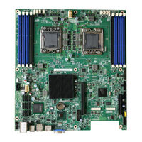
Intel S5500WB Specification (117 pages)
Product Specification
Brand:
Intel
| Category:
Server Board
| Size: 4.42 MB
Table of Contents
Revision History
2
Table of Contents
4
1 Introduction
15
Section Outline
15
Server Board Use Disclaimer
15
2 Server Board Overview
16
Table 1. Intel ® Server Board S5500WB Feature Set
16
Figure 1. Intel ® Server Board S5500WB 12V
18
Intel Server Board S5500WB Server Board
18
Figure 2. Intel Server Board S5500WB SSI
19
Figure 3. Intel ® Server Board S5500WB Components (both Skus Are Shown)
20
Server Board Connector and Component Layout
20
Table 12. Intel
21
Table 13. Intel
21
Board Rear Connector Placement
22
Figure 4. Rear Panel Connector Placement
22
Server Board Mechanical Drawings
22
Figure 5. Baseboard and Mounting Holes
23
Figure 6. Connector Locations
24
Figure 7. Primary Side Height Restrictions
25
Figure 8. Secondary Side Height Restrictions
26
Table 2. Intel ® Server Board S5500WB System Interconnects
21
3 Functional Architecture
27
High Level Product Features
27
Table 3. Intel ® Server Board S5500WB Features
27
Functional Block Diagram
28
Figure 9. Intel ® Server Board S5500WB Functional Block Diagram
28
Processor Subsystem
29
Processor Support
29
Processor Population Rules
29
Table 4. Mixed Processor Configurations
30
Installing or Replacing the Processor
31
Figure 10. Lifting the Load Lever of ILM Cover
31
Figure 11. Removing the Socket Cover
31
Figure 12. Installing Processor
32
Figure 13. Package Installation/Remove Feature
33
Qpi)
34
Figure 14. Installing/Removing Heatsink
34
Figure 15. Intel QPI Link
34
Intel ® Quickpath Memory Controller
35
Supported Memory
35
Memory Subsystem Nomenclature
35
ECC Support
36
Memory Reservation for Memory-Mapped Functions
36
High-Memory Reclaim
36
Table 5. DIMM Nomenclature
36
Memory Population Rules
37
Installing and Removing Memory
37
Figure 16. Memory Channel Population
37
Figure 17. Installing Memory
38
Channel-Independent Mode
39
Memory RAS
39
Memory Error LED
40
Intel 5500 Chipset IOH
40
IOH24D PCI Express
40
Figure 18. Mirroring Memory Configuration
40
Management Engine
41
Table 6. IOH24D PCI Express* Bus Segments
41
Intel 82801Jx I/O Controller Hub (ICH10R)
42
Serial ATA Support
42
USB 2.0 Support
43
Network Interface Controller (NIC)
44
Table 7. NIC 1 Status LED
44
LAN Connector Ordering
45
MAC Address Definition
45
Integrated Baseboard Management Controller
45
Integrated BMC Embedded LAN Channel
47
Figure 19. Integrated BMC Hardware
47
RMM3 Advanced Management Board
48
3.10 Serial Ports
48
3.11 Wake-Up Control
48
3.12 Integrated Video Support
48
Table 8. RMM3 Features
48
Dual Video
49
Front Panel Video
49
Table 10. Dual Video Options
49
Table 9. Supported Video Modes
49
Video Modes
49
3.13 I/O Slots
50
X16 Riser Slot Definition
50
PE WIDTH Strapping
50
Slot 1 PCI Express* X8 Connector
50
Table 11. PEWIDTH Strapping Bits
50
I/O Module Connector
51
4 Intel I/O Expansion Modules
52
5 Platform Management Features
54
BIOS Feature Overview
54
EFI Support
54
BIOS Recovery
54
BMC Feature Overview
54
Server Engines Pilot II Controller
54
BMC Firmware
55
BMC Basic Features
55
Table 14: BMC Basic Features
55
BMC Advanced Features
56
Management Engine (ME)
56
Overview
56
Table 15. Advanced Features
56
BMC - Management Engine Interaction
57
Data Center Manageability Interface
57
Other Platform Management
57
Wake on LAN (WOL)
57
PCI Express* Power Management
57
Pmbus
57
I2C\SMBUS Architecture Block
58
I2C\SMBUS Device Addresse
58
Figure 20. S5500WB I2C\SMBUS Block Diagram
58
Table 16. I2C/Smbus Device Address Assignment
58
6 Configuration Jumpers
60
Figure 21: Jumper Blocks (J1B5, J1C2, J1C3, J1B4, J6A3, J6A2, J7A2)
60
Force IBMC Update (J1B5)
61
Table 17: Server Board Jumpers (J1B5, J1C2, J1C3, J1B4, J6A3, J6A2)
61
Table 18. Force IBMC Update Jumper
61
Password Clear (J1C2)
62
Table 19. Password Clear Jumper
62
BIOS Recovery Mode (J1C3)
63
Table 20. BIOS Recovery Mode Jumper
63
Reset BIOS Configuration (J1B4)
64
Video Master (J6A3)
64
Table 21. Reset BIOS Jumper
64
Table 22. Video Master Jumper
64
ME Firmware Force Update (J7A2)
65
Serial Interface (J6A2)
65
7 Connector/Header Locations and Pin-Out
66
Power Connectors
66
Table 23. SSI SKU 24-Pin 2X12 Connector (J9B3)
66
Table 24. CPU 12V Power 2X4 Connector (J5K1)
66
Table 25. SSI Power Control (J9D1)
66
Table 26. 12-V Only 2X4 Connector (Replaces EPSD12V 2X12 Connector) (J9D2)
67
Table 27. 12-V Only Power Control (Replaces the 1X5 Power Control) (J9D1)
67
Table 28. Peripheral Power (Only for 12-V Only SKU) (J8K2) (Ipn: C22293-003 MOLEX CONNECTOR CORPORATION 43045-0627)
67
System Management Headers
68
Intel Remote Management Module 3 (Intel RMM3) Connector
68
BMC Power Cycle Header (12V Only)
68
Table 29. Intel ® RMM3 Connector Pin-Out (J5B1)
68
Table 30. BMC Power Cycle Header (J1D2)
68
Hard Drive Activity (Input) LED Header
69
IPMB Header
69
SGPIO Header
69
SSI Control Panel Connector
69
Table 31. IPMB Header 4-Pin (J1B2)
69
Table 32. SGPIO Header (J1B1)
69
Table 33. Front Panel SSI Standard 24-Pin Connector Pin-Out (J1E2)
69
Chassis Identify Button
70
NMI Button
70
Power Button
70
Reset Button
70
Power LED
71
System Status LED
71
Table 34. Power LED Indicator States
71
Table 35. System Status LED
72
Chassis ID LED
73
I/O Connectors
73
PCI Express* Connectors
73
Table 36. Chassis ID LED Indicator States
73
Table 37. Slot 6 Riser Connector (J4B1)
73
Table 38. Slot 1 PCI Express* X8 Connector (J1B3)
74
VGA Connectors
75
Table 39. VGA External Video Connector (J6A1)
75
NIC Connectors
76
Table 40. VGA Internal Video Connector (J1D1)
76
Table 41. RJ-45 10/100/1000 NIC Connector Pin-Out (J8A2, J9A1)
77
SATA Connectors
78
Intel I/O Expansion Module Connector
78
Table 42. SATA Connectors
78
Table 43. 50-Pin Intel ® I/O Expansion Module Connector Pin-Out (J2B1, J3B1)
79
Serial Port Connectors
80
USB Connectors
80
Table 44. External RJ-45 Serial Port a (COM1) (J7A1)
80
Table 45. Internal 9-Pin Serial B (COM2) (J1A2)
80
Table 46. External USB Connector (J8A1, J9A1))
80
Table 47. Internal USB Connector (J1C1 and J9A2)
80
Fan Headers
81
Table 48. Low-Profile Internal USB Connector (J1E3)
81
Table 49. SSI 4-Pin Fan Connector (J2K2, J2K3, J3K1, J7K1, J8K4, J8K5)
81
Table 50. 8-Pin Fan Connector (J2K1 & J8K3) (MOLEX CONNECTOR CORPORATION 53398-0890 or 53398-0871 )
81
8 Intel Light-Guided Diagnostics
82
5-V Standby LED
82
Figure 22: 5-V Standby Status LED Location
82
Fan Fault Leds
83
System Status LED
83
Figure 23. Fan Fault LED Locations
83
Figure 24. System Status LED Location
84
Table 51. System Status LED
85
DIMM Fault Leds
87
Figure 25. DIMM Fault Leds Locations
87
POST Code Diagnostic Leds
88
Figure 26. Rear Panel Diagnostic Leds
88
Front Panel Support
89
Table 52. Standard Front Panel Functionality
89
9 Design and Environmental Specifications
90
Fan Speed Control Thermal Management
90
Figure 27: Thermal Zones
90
Figure 28: Location of Fan Connectors
91
Table 53. Fan Connector Location & Detail
91
Thermal Sensors
92
Processor PECI Temperature Sensor
92
Figure 29. Fans and Sensors Block Diagram
92
Table 54. Fan Connector Location & Detail
92
Memory Temperature Sensor
93
Board Temperature Sensor
93
Thermals Sensor Placement
93
Heatsinks
94
Figure 30: Temp Sensor Location
94
Figure 31. Unified Retention System and Unified Backplate Assembly
95
Unified Retention System Support
95
Errors
96
Prochot
96
Thermtrip
96
Caterr
96
10 Power Subsystem
97
10.1 Server Board Power Distribution
97
10.2 Power Supply Compatibility
97
10.3 Power Sequencing and Reset Distribution
98
11 Regulatory and Certification Information
99
11.1 Product Regulation Requirements
99
Product Safety Compliance
99
Product EMC Compliance - Class a Compliance
99
Certifications / Registrations / Declarations
99
11.2 Product Regulatory Compliance Markings
100
11.3 Electromagnetic Compatibility Notices
100
Revision
100
FCC Verification Statement (USA)
100
Table 55: Product Regulatory Compliance Markings
100
ICES-003 (Canada)
101
Europe (CE Declaration of Conformity)
102
BSMI (Taiwan)
102
KCC (Korea)
102
Appendix A: POST Code LED Decoder
103
Table 56. POST Progress Code LED Example
104
Table 57. Diagnostic LED POST Code Decoder
105
Appendix B: Video POST Code Errors
110
Table 58. POST Error Messages and Handling
110
Glossary
114
Table 59: Glossary
114
Reference Documents
117
Advertisement
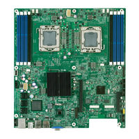
Intel S5500WB Technical Product Specification (116 pages)
A dual socket server
Brand:
Intel
| Category:
Server Board
| Size: 6.51 MB
Table of Contents
Table of Contents
4
1 Introduction
15
Section Outline
15
Server Board Use Disclaimer
15
2 Server Board Overview
16
Table 1. Intel ® Server Board S5500WB Feature Set
16
Figure 1. Intel ® Server Board S5500WB 12V
18
Intel ® Server Board S5500WB Server Board
18
Figure 2. Intel Server Board S5500WB SSI
19
Figure 3. Intel ® Server Board S5500WB Components (both Skus Are Shown)
20
Table 2. Intel ® Server Board S5500WB System Interconnects
21
Board Rear Connector Placement
22
Figure 4. Rear Panel Connector Placement
22
Server Board Mechanical Drawings
22
Figure 5. Baseboard and Mounting Holes
23
Figure 6. Connector Locations
24
Figure 7. Primary Side Height Restrictions
25
Figure 8. Secondary Side Height Restrictions
26
Server Board Connector and Component Layout
20
3 Functional Architecture
27
High Level Product Features
27
Table 3. Intel ® Server Board S5500WB Features
27
Functional Block Diagram
28
Figure 9. Intel ® Server Board S5500WB Functional Block Diagram
28
Intel ® Xeon ® 5500 Series
29
Processor Support
29
Processor Population Rules
29
Table 4. Mixed Processor Configurations
30
Installing or Replacing the Processor
31
Figure 10. Lifting the Load Lever of ILM Cover
31
Figure 11. Removing the Socket Cover
32
Figure 12. Installing Processor
32
Figure 13. Package Installation/Remove Feature
33
Qpi)
34
Figure 14. Installing/Removing Heatsink
34
Intel ® Quickpath Memory Controller
35
Supported Memory
35
Figure 15. Intel ® QPI Link
35
Memory Subsystem Nomenclature
36
Table 5. DIMM Nomenclature
36
ECC Support
37
Memory Reservation for Memory-Mapped Functions
37
High-Memory Reclaim
37
Memory Population Rules
37
Figure 16. Memory Channel Population
37
Installing and Removing Memory
38
Figure 17. Installing Memory
38
Channel-Independent Mode
39
Memory RAS
39
Memory Error LED
40
Intel ® 5500 Chipset IOH
40
Figure 18. Mirroring Memory Configuration
40
IOH24D PCI Express
41
Table 6. IOH24D PCI Express* Bus Segments
41
Management Engine
42
Intel 82801Jx I/O Controller Hub (ICH10R)
42
Serial ATA Support
43
USB 2.0 Support
43
Network Interface Controller (NIC)
44
MAC Address Definition
44
Table 7. NIC Status LED
44
LAN Connector Ordering
45
Integrated Baseboard Management Controller
45
Integrated BMC Embedded LAN Channel
47
RMM3 Advanced Management Board
47
3.10 Serial Ports
47
Figure 19. Integrated BMC Hardware
47
Table 8. RMM3 Features
47
3.11 Wake-Up Control
48
3.12 Integrated Video Support
48
Video Modes
48
Dual Video
48
Table 9. Supported Video Modes
48
Front Panel Video
49
3.13 I/O Slots
49
X16 Riser Slot Definition
49
PE WIDTH Strapping
49
Table 10. Dual Video Options
49
Table 11. PEWIDTH Strapping Bits
49
Slot 1 PCI Express* X8 Connector
50
I/O Module Connector
50
Table 12. Intel ® I/O Expansion Module Bus PEWIDTH Bits
50
4 Intel® I/O Expansion Modules
51
Table 13. Intel ® I/O Expansion Module Product Codes
51
5 Platform Management Features
53
BIOS Feature Overview
53
EFI Support
53
Intel Rapid Boot Toolkit
53
BIOS Recovery
53
BMC Feature Overview
53
Server Engines Pilot II Controller
54
BMC Firmware
54
BMC Basic Features
55
BMC Advanced Features
55
Table 14. Advanced Features
55
Management Engine (ME)
56
Overview
56
BMC - Management Engine Interaction
56
Data Center Manageability Interface
56
Other Platform Management
56
Wake on LAN (WOL)
56
PCI Express* Power Management
57
Pmbus
57
SMBUS Architecture Block
57
SMBUS Device Addresses
57
Figure 20. S5500WB SMBUS Block Diagram
57
Table 15. Smbus Device Address Assignment
57
6 Configuration Jumpers
59
Figure 21: Jumper Blocks (J1B5, J1C2, J1C3, J1B4, J6A3, J6A2, J7A2)
59
Force IBMC Update (J1B5)
60
Table 16: Server Board Jumpers (J1B5, J1C2, J1C3, J1B4, J6A3, J6A2)
60
Table 17. Force IBMC Update Jumper
60
Password Clear (J1C2)
61
Table 18. Password Clear Jumper
61
BIOS Recovery Mode (J1C3)
62
Table 19. BIOS Recovery Mode Jumper
62
Reset BIOS Configuration (J1B4)
63
Video Master (J6A3)
63
Table 20. Reset BIOS Jumper
63
Table 21. Video Master Jumper
63
ME Firmware Force Update (J7A2)
64
Serial Interface (J6A2)
64
7 Connector / Header Locations and Pin-Out
65
Power Connectors
65
Table 22. SSI SKU 24-Pin 2X12 Connector (J9B1)
65
Table 23. CPU 12V Power 2X4 Connector (J5K1)
65
Table 24. SSI Power Control (J9D1)
65
Table 25. 12-V Only 2X4 Connector (Replaces EPSD12V 2X12 Connector) (J9D2)
65
Table 26. 12-V Only Power Control (Replaces the 1X5 Power Control) (J9D1)
66
Table 27. Peripheral Power (Only for 12-V Only SKU) (J8K2)
66
System Management Headers
67
Intel ® Remote Management Module 3 (Intel ® RMM3) Connector
67
BMC Power Cycle Header (12V Only)
67
Table 28. Intel ® RMM3 Connector Pin-Out (J5B1)
67
Table 29. BMC Power Cycle Header (J1D2)
67
Hard Drive Activity (Input) LED Header
68
IPMB Header
68
SGPIO Header
68
SSI Control Panel Connector
68
Table 30. IPMB Header 4-Pin (J1B2)
68
Table 31. SGPIO Header (J1B1)
68
Table 32. Front Panel SSI Standard 24-Pin Connector Pin-Out (J1E1)
68
NMI Button
69
Power Button
69
Reset Button
69
Chassis Identify Button
70
Power LED
70
System Status LED
70
Table 33. Power LED Indicator States
70
Table 34. System Status LED
71
Chassis ID LED
72
Table 35. Chassis ID LED Indicator States
72
I/O Connectors
73
PCI Express* Connectors
73
Table 36. Slot 6 Riser Connector (J4B1)
73
Table 37. Slot 1 PCI Express* X8 Connector (J1B3)
74
VGA Connectors
75
Table 38. VGA External Video Connector (J6A1)
75
Table 39. VGA Internal Video Connector (J1D1)
75
NIC Connectors
76
Table 40. RJ-45 10/100/1000 NIC Connector Pin-Out (J8A2, J9A1)
76
SATA Connectors
77
Intel ® I/O Expansion Module Connector
77
Table 41. SATA Connectors
77
Table 42. 50-Pin Intel ® I/O Expansion Module Connector Pin-Out (J2B1, J3B1)
78
Serial Port Connectors
79
USB Connectors
79
Table 43. External RJ-45 Serial Port a (COM1) (J7A1)
79
Table 44. Internal 9-Pin Serial B (COM2) (J1A2)
79
Table 45. External USB Connector (J8A1, J9A1))
79
Table 46. Internal USB Connector (J1C1 and J9A2)
79
Fan Headers
80
Table 47. Low-Profile Internal USB Connector (J1E2)
80
Table 48. SSI 4-Pin Fan Connector (J2K2, J2K3, J3K1, J7K1, J8K4, J8K5)
80
Table 49. 8-Pin Fan Connector (J2K1 & J8K3)
80
8 Intel Light-Guided Diagnostics
81
5-V Standby LED
81
Figure 22: 5-V Standby Status LED Location
81
Fan Fault Leds
82
System Status LED
82
Figure 23. Fan Fault LED Locations
82
Figure 24. System Status LED Location
83
Table 50. System Status LED
83
DIMM Fault Leds
86
Figure 25. DIMM Fault Leds Locations
86
POST Code Diagnostic Leds
87
Figure 26. Rear Panel Diagnostic Leds
87
Front Panel Support
88
Table 51. Standard Front Panel Functionality
88
9 Design and Environmental Specifications
89
Fan Speed Control Thermal Management
89
Figure 27: Thermal Zones
89
Figure 28: Location of Fan Connectors
90
Table 52. Fan Connector Location & Detail
90
Thermal Sensors
91
Processor PECI Temperature Sensor
91
Figure 29. Fans and Sensors Block Diagram
91
Table 53. Fan Connector Location & Detail
91
Memory Temperature Sensor
92
Board Temperature Sensor
92
Thermals Sensor Placement
92
Heatsinks
93
Figure 30: Temp Sensor Location
93
Figure 31. Unified Retention System and Unified Backplate Assembly
94
Unified Retention System Support
94
Errors
95
Prochot
95
Thermtrip
95
Caterr
95
10 Power Subsystem
96
10.1 Server Board Power Distribution
96
10.2 Power Supply Compatibility
96
Figure 32. Power Distribution Diagram
96
10.3 Power Sequencing and Reset Distribution
97
11 Regulatory and Certification Information
98
11.1 Product Regulation Requirements
98
Product Safety Compliance
98
Product EMC Compliance - Class a Compliance
98
Certifications / Registrations / Declarations
98
11.2 Product Regulatory Compliance Markings
99
11.3 Electromagnetic Compatibility Notices
99
FCC Verification Statement (USA)
99
Table 54: Product Regulatory Compliance Markings
99
ICES-003 (Canada)
100
Europe (CE Declaration of Conformity)
101
BSMI (Taiwan)
101
KCC (Korea)
101
Appendix A: POST Code LED Decoder
102
Figure 33. Diagnostic LED Placement Diagram
102
Table 55. POST Progress Code LED Example
103
Table 56. Diagnostic LED POST Code Decoder
104
Appendix B: Video POST Code Errors
109
Table 57. POST Error Messages and Handling
109
Glossary
113
Table 58: Glossary
113
Reference Documents
116
Intel S5500WB Spares/Parts List And Configuration Manual (9 pages)
Server Board and System
Brand:
Intel
| Category:
Server Board
| Size: 0.25 MB
Table of Contents
Revision History
2
Product Descriptions - Overview
3
Product Overview
3
Production Order Codes
4
Intel ® System Management Software - Upgrade Order Codes
7
Vmware Vsphere* and Vcenter* Server Skus
8
Advertisement
Intel S5500WB Spares/Parts List And Configuration Manual (8 pages)
Configuration Guide
Brand:
Intel
| Category:
Server Board
| Size: 0.2 MB
Table of Contents
Revision History
2
Product Overview
3
Production Order Codes
4
Intel® System Management Software - Upgrade Order Codes
6
Advertisement
Related Products
Intel S5520SC
Intel S5500BCR
Intel S5500HCVR
Intel S5520HCT
Intel S5500WB12V
Intel S5500WBR
Intel Server Board S5500HV
Intel S5000VSASATA
Intel S5000XVNSAS - Boxed Workstn Board Integrate 4PORTSAS
Intel S5000VSASCSIR
Intel Categories
Motherboard
Computer Hardware
Server
Server Board
Desktop
More Intel Manuals
Login
Sign In
OR
Sign in with Facebook
Sign in with Google
Upload manual
Upload from disk
Upload from URL