Intel S5500BC - Server Board Motherboard User Manual
User guide
Hide thumbs
Also See for S5500BC - Server Board Motherboard:
- Spares parts list & configuration manual (22 pages) ,
- Quick start user manual (1 page) ,
- Product specification (119 pages)
Table of Contents
Advertisement
Advertisement
Table of Contents

Related Manuals for Intel S5500BC - Server Board Motherboard


Summary of Contents for Intel S5500BC - Server Board Motherboard
- Page 1 ® Intel Server Board S5500BC User’s Guide Intel Order Number E52448-001...
- Page 2 Intel products are not designed, intended or authorized for use in any medical, life saving, or life sustaining applications or for any other application in which the failure of the Intel product could create a situation where personal injury or death may occur.
- Page 3 ® Intel Server Board S5500BC User’s Guide...
- Page 4 ® Intel Server Board S5500BC User’s Guide...
-
Page 5: Preface
This document provides a brief overview of the features of the board/chassis, a list of accessories or other components you may need, troubleshooting ® information, and instructions on how to add and replace components on the Intel Server Board S5500BC. For the latest version of this manual, see http://support.intel.com/... -
Page 6: Product Accessories
DIMMs, hard drive, CD-ROM or DVD-ROM drive, and/or operating system. For information about which accessories, memory, processors, and third-party hardware were tested and can be used with your board, and for ordering information for Intel products, see: http://support.intel.com/support/motherboards/server/S5500BC... - Page 7 Use this Document or Software To make sure your system falls within Power Budget the allowed power budget ® ® For software to manage your Intel Intel Server Management Software server • For drivers Driver (for an extensive list of drivers available) •...
- Page 8 ® viii Intel Server Board S5500BC User’s Guide...
-
Page 9: Safety Information
Safety Information Important Safety Instructions Read all caution and safety statements in this document before performing any of the instructions. See also Intel Server Boards and Server Chassis Safety Information on the ® Intel Server Deployment Toolkit 3.0 CD and/or at http://support.intel.com/support/... - Page 10 ® Intel Server System SR1630BC User’s Guide...
-
Page 11: Warnings
Take care to grip with, but not squeeze, the pliers or other tool you use to remove a jumper, or you may bend or break the pins on the board. ® Intel Server System SR1630BC User’s Guide... - Page 12 ® Intel Server System SR1630BC User’s Guide...
-
Page 13: Table Of Contents
List of Figures ® Figure 1. Intel Server Board S5500BC..................1 Figure 2. Server Board Connector and Component Locations ..........3 Figure 3. Configuration Jumper Locations .................5 Figure 4. Back Panel Connectors....................7 Figure 5. DIMM Configuration Diagram..................10 Figure 6. Channel Slots Configuration ..................11... - Page 14 ® Intel Server Board S5500BC User’s Guide...
- Page 15 Utility....................25 Starting Setup.......................25 If You Cannot Access Setup..................25 Setup Menus ........................25 Upgrading the BIOS......................27 Preparing for the Upgrade ....................27 BIOS Recovery Mode and BIOS Flash Update............28 Recovering the BIOS ......................28 Clearing the Password......................30 ® Intel Server Board S5500BC User’s Guide...
- Page 16 Electromagnetic Compatibility Notices ................. FCC (USA) ........................Industry Canada (ICES-003)..................Europe (CE Declaration of Conformity)................ Taiwan Declaration of Conformity (BSMI)..............Korean Compliance...................... Appendix B: LED Decoder ..................51 Appendix C: Getting Help ..................51 Warranty Information......................® Intel Server Board S5500BC User’s Guide...
- Page 17 ® Appendix D: Intel Server Issue Report Form............® Intel Server Board S5500BC User’s Guide xvii...
- Page 18 ® xviii Intel Server Board S5500BC User’s Guide...
- Page 19 List of Tables ® Table 1. Intel Server Board S5500BC Feature Summary ............2 Table 2. Configuration Jumper [J4A1]..................5 Table 3. NIC LEDs ........................Table 4. Setup Menu Key Use ....................26 Table 5. POST Error Beep Codes....................43 Table 6. Diagnostic LED Placement Diagram ................51...
- Page 20 ® Intel Server Board S5500BC User’s Guide...
-
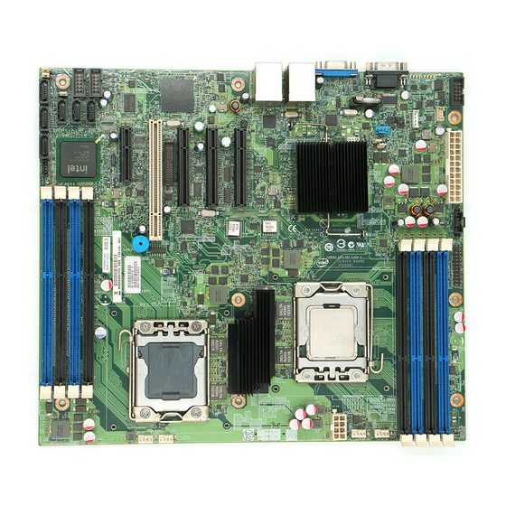
Page 21: Figure 1. Intel ® Server Board S5500Bc
Server Board Features ® This chapter briefly describes the main features of the Intel Server Board S5500BC. This chapter provides illustrations of the product, a list of the server board features, and diagrams showing the location of important components and connections on the server system. -
Page 22: Table 1. Intel ® Server Board S5500Bc Feature Summary
IOH 5500 chipset. • One Gigabit Ethernet device (82567) connects to the Gigabit ® LAN Connect Interface / LAN Connect Interface on the Intel ICH10R. Expansion Capabilities One riser slot supporting one low-profile half-length PCI Express* 2.0 x8 add-in card. -
Page 23: Figure 2. Server Board Connector And Component Locations
CPU Power USB2.0 header Connector SATA 5 ID LED CPU Socket 1 ® SATA 4 External Serial B Intel IOH 5500 header chipset Slot 3, PCI Express* x4 SATA Key CPU Socket 2 Slot 4, 32-bit/33 MHz System fan 3 header... - Page 24 Slot 6, PCI Express* x8 Power Supply SATA SGPIO (Riser card) Auxiliary Connector Slot 7, PCI Express* x8 SSI 24-pin Front SATA 0 Panel connector Back panel I/O ports System fan 2 header SATA 1 ® Intel Server Board S5500BC User’s Guide...
-
Page 25: Figure 3. Configuration Jumper Locations
NOTE: These pins should not be jumpered for normal operation. J2D2: CMOS Clear These pins should have a jumper in place for normal system operation. (Default) ® Intel Server Board S5500BC User’s Guide... - Page 26 NOTE: The system will boot from EFI- bootable recovery media with a recovery BIOS image. J8B5: ME Force Update These pins should have a jumper in place for normal system operation. (Default) ME force update model. ® Intel Server Board S5500BC User’s Guide...
-
Page 27: Figure 4. Back Panel Connectors
USB Port 8-9 Video NIC Port 1 USB Port 6-7 NIC Port 2 (MGMT) Figure 4. Back Panel Connectors The NIC LEDs at the right and left of each NIC provide the following information. ® Intel Server Board S5500BC User’s Guide... -
Page 28: Raid Support
® ® The Intel Server Board provides six SATA ports (3 Gbps) via ICH10R with Intel Embedded Server RAID Technology, with SW RAID levels 0/1/10. Optional support for SW RAID 5 with activation key. The BIOS Setup utility provides multiple drive configuration options on the Advanced | Mass Storage Controller Configuration setup page, some of which affect the ability to configure RAID. -
Page 29: Hardware Requirements
® If RAID 5 is needed, you can install the optional Intel RAID Activation Key AXXRAKSW5. To enable RAID 5, this activation key is placed on the SATA Key connector located on the right side of the server board. For information on how to install ®... -
Page 30: Figure 5. Dimm Configuration Diagram
For two slots per channel configuration, the server board requires DDR3 DIMMs within a channel to be populated starting with the DIMM farthest from the processor. See Figure 6. For a complete list of supported memory DIMMs, see the links under “Additional Information and Software”. ® Intel Server Board S5500BC User’s Guide... -
Page 31: Figure 6. Channel Slots Configuration
CAS latency, and so forth). Memory Sparing and Mirroring ® The spare mode is not supported by the Intel Server Board S5500BC. With memory mirroring, the system maintains two copies of all data in the memory subsystem. If a DIMM fails, the data is not lost because the second copy of the data is available from the mirrored DIMM in the opposite channel. -
Page 32: Power Supply
Intel RAID Activation Key ® If RAID 5 is needed, you can install the optional Intel RAID Activation Key AXXRAKSW5. To enable RAID 5, this activation key is placed on the SATA Key connector located on the right side of the server board (see Figure 2). For information on ®... -
Page 33: Chapter 2: Hardware Installations And Upgrades
Hardware Installations and Upgrades Before You Begin Before working with your server product, pay close attention to the “Safety Information” at the beginning of this manual. Tools and Supplies Needed • Phillips* (cross head) screwdrivers (#1 bit and #2 bit) •... -
Page 34: Figure 7. Installing Memory
5. Gently spread the retaining clips at each end of the socket. The DIMM lifts from the socket. 6. Holding the DIMM by the edges, lift it from the socket, and store it in an anti-static package. ® Intel Server Board S5500BC User’s Guide... -
Page 35: Figure 8. Lifting The Load Lever
5. Locate the processor socket and open the socket lever (see Figure 8). Figure 8. Lifting the Load Lever 6. Open the load plate (see letter “A” in Figure 8 and letter “B” in Figure 9). ® Intel Server Board S5500BC User’s Guide... -
Page 36: Figure 9. Open The Load Plate
7. Remove the socket protective cover (see Figure 10). Figure 10. Remove the Socket Protective Cover 8. Take the processor out of the box and remove the protective shipping cover (Figure 11). Figure 11. Remove the Processor Protective Cover ® Intel Server Board S5500BC User’s Guide... -
Page 37: Figure 12. Installing The Processor
2. Align heat sink fins to the front and back of the chassis for correct airflow. Airflow goes from front-to-back of chassis. 3. Each heat sink has four captive fasteners and should be tightened as shown. ® Intel Server Board S5500BC User’s Guide... -
Page 38: Figure 14. 2U Reference Heat Sink Assembly
2. Turn off all peripheral devices connected to the server and turn off the server. 3. Remove the AC power cord from the server. 4. Remove the server's cover. 5. Unplug the processor fan cable from the server board. ® Intel Server Board S5500BC User’s Guide... - Page 39 10. Raise the CPU load plate. 11. Remove the processor. 12. If installing a replacement processor, see “Installing the Processor”. Otherwise, install the protective socket cover over the empty processor socket and reinstall the chassis cover. ® Intel Server Board S5500BC User’s Guide...
-
Page 40: Figure 15. Removing The Pci Riser Assembly From The Server System
Peripherals and add-in cards are not included in your system and you must purchase them separately. The riser card at PCI slot 6 of the board supports a low-profile half-length PCI ® Express* add-in card. Refer to the “Intel SR1630BC System User Guide” for more detailed information on how to install a PCI card. -
Page 41: Figure 16. Installing A Pci Card In A Riser Card
Caution: Press the riser card straight down into the slot. Tipping the riser card while installing it into the slot may damage the riser card or slot on the server board. 4. Use the screw removed in Step 1 to secure the riser card assembly to the chassis. ® Intel Server Board S5500BC User’s Guide... -
Page 42: Replacing The Backup Battery
5. Insert the tip of a small flat bladed screwdriver, or an equivalent, under the tab in the plastic retainer. Gently push down on the screwdriver to lift the battery. 6. Remove the battery from its socket. ® Intel Server Board S5500BC User’s Guide... -
Page 43: Figure 17. Replacing The Backup Battery
8. Remove the new lithium battery from its package, and, being careful to observe the correct polarity, insert it in the battery socket. 9. Close the chassis. 10. Run Setup to restore the configuration settings to the RTC. ® Intel Server Board S5500BC User’s Guide... - Page 44 ® Intel Server Board S5500BC User’s Guide...
-
Page 45: Chapter 3: Server Utilities
Server Utilities Using the BIOS Setup Utility This section describes the BIOS Setup Utility options, which you use to change server configuration defaults. You can run BIOS Setup with or without an operating system being present. Refer to “Additional Information and Software” for a link to the Technical Product Specification where you can find details about specific BIOS setup screens. -
Page 46: Table 4. Setup Menu Key Use
If “No” is selected and the <Enter> key is pressed, or if <Esc> is pressed, the user is returned to where they were before <F9> was pressed without affecting any existing field values. ® Intel Server Board S5500BC User’s Guide... -
Page 47: Upgrading The Bios
Recording the Current BIOS Settings 1. Boot the computer and press <F2> when you see the message: Press <F2> key if you want to run SETUP 2. Write down the current settings in the BIOS Setup program. ® Intel Server Board S5500BC User’s Guide... -
Page 48: Bios Recovery Mode And Bios Flash Update
BIOS. Note: The entire process takes two to four minutes. Recovering the BIOS The following steps boot the recovery BIOS and flashes the normal BIOS: ® Intel Server Board S5500BC User’s Guide... -
Page 49: Figure 18. Bios Recovery Jumper
1 and 2. 9. Plug the system into the AC power source and power it up to confirm the recovery was successful. 10. Do NOT interrupt the BIOS POST during the first boot. ® Intel Server Board S5500BC User’s Guide... -
Page 50: Figure 19. Password Recovery Jumper
6. Return the Password Clear jumper to the Password Clear Protect position, covering pins 1 and 2. Reconnect AC power and power up the server. 7. Close the server chassis. The password is cleared and can be reset by going into the BIOS setup. ® Intel Server Board S5500BC User’s Guide... -
Page 51: Figure 20. Cmos Recovery Jumper
7. Return the CMOS Clear jumper to the spare location, covering pins 1 and 2. 8. Close the server chassis; reconnect the AC power and power up the system. The CMOS is now cleared and you can reset it by going into the BIOS setup. ® Intel Server Board S5500BC User’s Guide... - Page 52 ® Intel Server Board S5500BC User’s Guide...
-
Page 53: Chapter 4: Troubleshooting
In addition to the server firmware and files, you must also update any drivers used for components you installed in your system, such as video and network drivers. Intel provides a package called the “Platform Confidence Test” that may help with your diagnostics. Refer to “Additional Information and Software”... -
Page 54: Problems Following Initial System Installation
Are all integrated components from the tested components lists? Check the tested memory and chassis lists, as well as the supported hardware and operating system list. Refer to the “Additional Information and Software” for links to the tested component lists. ® Intel Server Board S5500BC User’s Guide... -
Page 55: Hardware Diagnostic Testing
Once the system boots up, the operating system prompt displays on the screen. The prompt varies according to the operating system. If the operating system prompt does not display, see “No Characters Display on Screen”. ® Intel Server Board S5500BC User’s Guide... -
Page 56: Specific Problems And Corrective Actions
Remove the processor(s) and re-seat them. • Make sure the chassis standoffs are installed only below mounting holes. Misplaced standoffs can contact the pins on the bottom of the server board and cause a short. ® Intel Server Board S5500BC User’s Guide... -
Page 57: No Characters Display On Screen
Are the brightness and contrast controls properly adjusted on the video monitor? See the manufacturer's documentation. • Are the video monitor's signal and power cables properly installed? • Does this video monitor work correctly if plugged into a different system? ® Intel Server Board S5500BC User’s Guide... -
Page 58: System Cooling Fans Do Not Rotate Properly
Light Check the following: • Are the CD-ROM/DVD-ROM drive's power and signal cables properly installed? • Are all relevant switches and jumpers on the drive set correctly? • Is the drive properly configured? ® Intel Server Board S5500BC User’s Guide... -
Page 59: Cannot Connect To A Server
• Try reseating the adapter first; then try a different slot if necessary. • The network driver files may be corrupt or deleted. Delete and then reinstall the drivers. • Run the diagnostics. ® Intel Server Board S5500BC User’s Guide... -
Page 60: System Boots When Installing Pci Card
Uninstall and reinstall the software. Make sure all necessary files are installed. • If the problems are intermittent, there may be a loose cable, dirt in the keyboard (if keyboard input is incorrect), a marginal power supply, or other random component failures. ® Intel Server Board S5500BC User’s Guide... -
Page 61: Devices Are Not Recognized Under Device Manager
Devices are not Recognized under Device Manager (Microsoft Windows* Operating System) ® The Microsoft Windows* operating systems do not include all of the drivers for the Intel chipsets, onboard NICs, and other components. Refer to “Additional Information and Software”... -
Page 62: Led Information
LED Information ® The Intel Server Board 5500BC includes LEDs that can aid in troubleshooting your system. The following lists these LEDs with a description of their use. LED Name Function Location LED Color Notes Aid in server function Front Panel... -
Page 63: Bios Post Beep Codes
The user can override this option by setting the POST Error Pause option as disabled on the BIOS setup Main screen. If this option is disabled, the system boots the operating system without user intervention. The default is disabled. ® Intel Server Board S5500BC User’s Guide... - Page 64 ® Intel Server Board S5500BC User’s Guide...
-
Page 65: Appendix A: Regulatory And Compliance Information
Product EMC Compliance - Class A Compliance Note: Legally the product is required to comply with Class A emission requirements as it is intended for a commercial type market place. Intel targets a 10 db margin to Class A Limits. -
Page 66: Important Note
IMPORTANT NOTE: ® The host system with the Intel Server Board S5500BC requires the use of a shielded LAN cable to comply with Immunity regulatory requirements. Use of non- shield cables may result in the product having insufficient protection against electromagnetic effects, which may cause improper operation of the product. - Page 67 Exporting MADE IN xxxxx (Provided by label, not Requirements silk screen) ® Model Designation Regulatory Examples (Intel Server Board) for boxed Identification type boards; or Board PB number for non- boxed boards (typically high-end boards) PB Free Marking Environmental Requirements Refer to the spec http://prodregs.intel.com/...
-
Page 68: Electromagnetic Compatibility Notices
(1) this device may not cause harmful interference, and (2) this device must accept any interference received, including interference that may cause undesired operation. For questions related to the EMC performance of this product, contact: Intel Corporation 5200 N.E. Elam Young Parkway Hillsboro, OR 97124-6497 1-800-628-8686 This equipment has been tested and found to comply with the limits for a Class A digital device, pursuant to Part 15 of the FCC Rules. -
Page 69: Industry Canada (Ices-003)
Korean Compliance (RRL) English translation of the notice above: 1. Type of Equipment (Model Name): On License and Product 2. Certification No.: On RRL certificate. Obtain certificate from local Intel representative ® Intel Server System SR1630BC User’s Guide... - Page 70 3. Name of Certification Recipient: Intel Corporation 4. Date of Manufacturer: Refer to date code on product 5. Manufacturer/Nation: Intel Corporation/Refer to country of origin marked on product ® Intel Server System SR1630BC User’s Guide...
-
Page 71: Figure 21. Diagnostic Led Placement Diagram
Appendix B: LED Decoder During the system boot process, the BIOS executes a number of platform configuration processes, each of which is assigned a specific hex POST code number. As each configuration routine is started, the BIOS displays the POST code to the POST Code Diagnostic LEDs on the back edge of the server board. -
Page 72: Table 7. Post Progress Code Led
Lower Nibble Host Processor 0x10h Power-on initialization of the host processor (bootstrap processor) 0x11h Host processor cache initialization (including AP) 0x12h Starting application processor initialization 0x13h SMM initialization Chipset 0x21h Initializing a chipset component ® Intel Server Board S5500BC User’s Guide... - Page 73 Detecting presence of memory 0x24h Programming timing parameters in the memory controller 0x25h Configuring memory parameters in the memory controller 0x26h Optimizing memory controller settings 0x27h Initializing memory, such as ECC init 0x28h Testing memory ® Intel Server Board S5500BC User’s Guide...
- Page 74 Resetting the video controller (VGA) 0x71h Disabling the video controller (VGA) 0x72h Enabling the video controller (VGA) Remote Console 0x78h Resetting the console controller 0x79h Disabling the console controller 0x7Ah Enabling the console controller ® Intel Server Board S5500BC User’s Guide...
- Page 75 Removable Media 0xB8h Resetting removable media device 0xB9h Disabling removable media device 0xBAh Detecting presence of a removable media device (IDE CD-ROM detection, and so on) 0xBCh Enabling / configuring a removable media device ® Intel Server Board S5500BC User’s Guide...
- Page 76 D 0xDE Trying to boot device selection E 0xDF Trying to boot device selection F Pre-EFI Initialization (PEI) Core 0xE0h Started dispatching early initialization modules (PEIM) 0xE1h Reserved for initialization module use (PEIM) ® Intel Server Board S5500BC User’s Guide...
- Page 77 0xFAh Operating system has requested the system to reset (ResetSystem () has been called) Pre-EFI Initialization Module (PEIM) / Recovery 0x30h Crisis recovery has been initiated because of a user request ® Intel Server Board S5500BC User’s Guide...
- Page 78 0xEBh Memory Test Error: memory failed Hardware BIST 0xEDh Population Error: RDIMMs and UDIMMs cannot be mixed in the system 0xEEh Mismatch Error: More than 2 Quad-Ranked DIMMs in a channel ® Intel Server Board S5500BC User’s Guide...
-
Page 79: Warranty Information
A searchable knowledgebase to search for product information throughout the support site 2. Send an email to Intel's technical support center using the following online form if you are still unable to obtain a solution to your issue: http://support.intel.com/ support/go/emf/index.htm 3. - Page 80 ® Intel Server Board S5500BC User’s Guide...
- Page 81 Date Submitted: _______________________________________________________ Company Name: ______________________________________________________ Contact Name: ________________________________________________________ Email Address: _______________________________________________________ Intel Server Product: ___________________________________________________ Priority (Critical, Hot, High, Low): _______________________________________ Brief Problem Description. Provide a brief description below. See the last page for space to include a detailed problem description.
- Page 82 HSC Firmware Version: DIMM_D1 MB and Vendor/part number Chassis Model: DIMM_D2 MB and Vendor/part number Chassis Model: DIMM_E1 MB and Vendor/part number DIMM_E2 MB and Vendor/part number ® Intel Server Board S5500BC User’s Guide...
- Page 83 PCI Slot 5 PCI Slot 6 PCI Slot 7 Video On-board Video Add-in Video On-Board NIC1 (10/100/1000 Gb) On-Board NIC2 (10/100/1000 Gb) Hard Drive Information Drive Type (SATA/ Hot-swap Make/Model Revision SAS) or Fixed ® Intel Server Board S5500BC User’s Guide...
- Page 84 Management Information On-Board Platform Instrumentation only ___________________________________ ® Intel Remote Management Module 3 _____________________________________ Complete Problem Description In the space below, provide a complete description of the steps used to reproduce the problem or a complete description of where the problem can be found. Please also include any details on troubleshooting already done.
- Page 85 ____________________________________________________________________ ® Intel Server Board S5500BC User’s Guide...
- Page 86 ® Intel Server Board S5500BC User’s Guide...
Need help?
Do you have a question about the S5500BC - Server Board Motherboard and is the answer not in the manual?
Questions and answers