Table of Contents
Advertisement
Quick Links
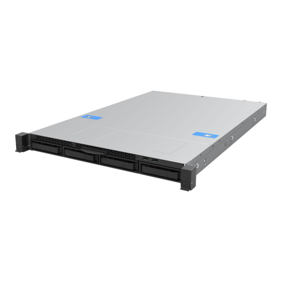
Intel® Server System
M20NTP1UR
System Integration and Service Guide
A guide providing instructions for the insertion and
extraction of system components and available
Intel accessories and spares
Rev. 1.0
February 2022
Delivering Breakthrough Data Center System Innovation – Experience What's Inside!
Advertisement
Table of Contents

Subscribe to Our Youtube Channel
Related Manuals for Intel M20NTP1UR


Summary of Contents for Intel M20NTP1UR
- Page 1 Intel® Server System M20NTP1UR System Integration and Service Guide A guide providing instructions for the insertion and extraction of system components and available Intel accessories and spares Rev. 1.0 February 2022 Delivering Breakthrough Data Center System Innovation – Experience What’s Inside!
- Page 2 <This page intentionally left blank>...
- Page 3 Intel® Server System M20NTP1UR - System Integration and Service Guide Document Revision History Date Revision Changes February 2022 First Public release.
- Page 4 You may not use or facilitate the use of this document in connection with any infringement or other legal analysis concerning Intel products described herein. You agree to grant Intel a non-exclusive, royalty-free license to any patent claim thereafter drafted which includes subject matter disclosed herein.
- Page 5 Intel recommends the following steps be taken when performing any procedures described within this document or while performing service to any computer system.
- Page 6 Intel® Server System M20NTP1UR - System Integration and Service Guide Weight of the system: Due to the weight of a system, Intel recommends carrying the system with two people supporting the • system from the sides or using a mechanical lift or a cart when moving the system from one location to another.
-
Page 7: Table Of Contents
Intel® Server System M20NTP1UR - System Integration and Service Guide Table of Contents 1. Introduction ................................13 Reference Documents and Support Collaterals ....................15 2. Essential System Component Installation ......................17 System Top Cover Removal / Installation ......................18 2.1.1 System Top Cover Removal............................ - Page 8 Intel® Server System M20NTP1UR - System Integration and Service Guide 5.2.3 ME Recovery Jumper ..............................51 Support Requirements for Thermal Management ................... 52 6. System Service and FRU Replacement ........................ 53 System Top Cover Removal / Installation ......................54 6.1.1 System Top Cover Removal............................
- Page 9 Intel® Server System M20NTP1UR - System Integration and Service Guide List of Figures Figure 1. Intel® Server System M20NTP1UR ..........................13 Figure 2. Intel® Server System M20NTP1UR Features ......................17 Figure 3. System Top Cover Screws ..............................18 Figure 4. System Cover Removal ................................ 18 Figure 5.
- Page 10 Intel® Server System M20NTP1UR - System Integration and Service Guide Figure 40. M.2 SSD Installation ................................40 Figure 41. OCP* Adapter Bay Filler Removal ..........................41 Figure 42. OCP* Mounting Bracket Installation ..........................41 Figure 43. OCP* Module Mounting Screws ............................ 42 Figure 44.
- Page 11 Intel® Server System M20NTP1UR - System Integration and Service Guide Figure 81. Riser Card Assembly Installation ..........................67 Figure 82. OCP* Module Removal ..............................68 Figure 83. OCP* Module Installation ..............................69 Figure 84. Backplane Removal (Step 1) ............................70 Figure 85.
- Page 12 Intel® Server System M20NTP1UR - System Integration and Service Guide List of Tables Table 1. Intel® Server System M20NTP1UR Reference Documents and Support Collaterals ........15 Table 2. PCIe* NVMe* Cable Routing ..............................38 Table 3. Intel® Server System M20NTP1UR Features ........................ 46 Table 4.
-
Page 13: Introduction
Intel® Server System M20NTP1UR - System Integration and Service Guide Introduction The Intel® Server System M20NTP1UR is a purpose-built rack mount server that delivers power and Gen Intel® Xeon® Scalable performance within a 1U form factor. The system supports up to two 3 processors, providing flexible performance. - Page 14 Chapter 4 – System Software Update and Configuration – A short overview describing the system software stack installed on new Intel servers and where to get the latest updates. System Service Chapter 5 –...
-
Page 15: Reference Documents And Support Collaterals
Reference Documents and Support Collaterals For additional information and other support collaterals related to this Intel server product, see Table Listed documents and utilities can be downloaded from the following Intel web sites or can be ordered through your local Intel support representative. https://www.intel.com/content/www/us/en/design/resource-design-center.html... - Page 16 Intel® Server System M20NTP1UR - System Integration and Service Guide Document Topic Document Title or Support Collateral Classification Intel® Server Firmware Update Utility (SYSFWUPDT) - Various operating Latest system software updates: system support BIOS and Firmware Intel® Server Firmware Update Utility User Guide Intel®...
-
Page 17: Essential System Component Installation
Intel® Server System M20NTP1UR - System Integration and Service Guide Essential System Component Installation The Intel® Server System M20NTP1UR is offered as an L6 integrated system. As received, the L6 system is not functional and will not boot. It requires additional components (sold separately) to be added to the system to make the base system configuration power on ready. -
Page 18: System Top Cover Removal / Installation
Intel® Server System M20NTP1UR - System Integration and Service Guide System Top Cover Removal / Installation Required Tools and Supplies Anti-static wrist strap and conductive workbench pad (recommended) • • Phillips* head screwdriver #1 2.1.1 System Top Cover Removal Removal of the top cover is necessary when installing or replacing any system component within the server chassis. -
Page 19: System Top Cover Installation
Align and place the top cover on the top edges of the chassis. • Slide it towards the front of the chassis until it locks into place (see Letter “A”). • Shipping Note: When transporting the server system, Intel recommends installing the three top cover screws before shipping (see Letter “B”). -
Page 20: Air Duct Removal And Installation
Intel® Server System M20NTP1UR - System Integration and Service Guide Air Duct Removal and Installation Required Tools and Supplies Anti-static wrist strap and conductive workbench pad (recommended) • 2.2.1 Air Duct Removal 1. Remove the system top cover (see Section 2.1.1). -
Page 21: 2.3 Processor Assembly And Installation
Intel® Server System M20NTP1UR - System Integration and Service Guide 2.3 Processor Assembly and Installation Caution: Fin edges of the processor heat sink are very sharp. Intel recommends wearing thin ESD protective gloves when handling the Processor Heatsink Module (PHM) during the following procedures. -
Page 22: Phm Assembly
Intel® Server System M20NTP1UR - System Integration and Service Guide 2.3.1 PHM Assembly To properly assemble the PHM and install it onto the server board, the procedures described in the following sections must be followed in the order specified. These instructions assume that the processor heat sink has the necessary Thermal Interface Material (TIM) (DOWSIL* TC-5888) already applied. -
Page 23: Figure 11. Processor Heat Sink Handling
Intel® Server System M20NTP1UR - System Integration and Service Guide 1. Locate the processor heat sink. To avoid damage, grasp it by its narrower sides as shown in Figure 11. Figure 11. Processor Heat Sink Handling 2. Place the heat sink bottom side up onto a flat surface. -
Page 24: Phm Installation
Intel® Server System M20NTP1UR - System Integration and Service Guide Align the Pin 1 indicator of processor carrier clip with one of the diagonally cut corners on the • base of the heat sink. Or (If present) look for the Pin 1 indicator on the corner of the heat sink label. -
Page 25: Figure 16. Phm Installation Onto Server Board
Intel® Server System M20NTP1UR - System Integration and Service Guide Caution: Processor socket pins are delicate and bend easily. Use extreme care when placing the PHM onto the processor socket. Do not drop it. 2. Install the Processor Heat Sink Module (PHM) on to the processor socket assembly Figure 16. -
Page 26: Memory Module Installation
Intel® Server System M20NTP1UR - System Integration and Service Guide Memory Module Installation Required Tools and Supplies Anti-static wrist strap and conductive workbench pad (recommended) • Note: See Appendix C for general memory population rules. 2.4.1 DIMM Installation 1. Remove the DIMM blank from the desired memory slot (See Figure 18) Figure 18. - Page 27 Intel® Server System M20NTP1UR - System Integration and Service Guide Align the notch at the bottom edge of the memory module with the key in the memory slot (see • Letter “B”). Insert the memory module into the slot (see Letter “C”). Push down on the memory module until •...
-
Page 28: System Options / Accessory Kit Installation
Intel® Server System M20NTP1UR - System Integration and Service Guide System Options / Accessory Kit Installation This chapter provides instructions for the integration of system options and other Intel accessories. If your integrated Intel server system did not come preinstalled with processors or memory, installation procedures... -
Page 29: System Top Cover Installation
Align and place the top cover on the top edges of the chassis. Slide it towards the front of the chassis until it locks into place (see Letter “A”). • Shipping Note: When transporting the server system, Intel recommends installing the three top cover screws before shipping (see Letter “B”). -
Page 30: Air Duct Removal And Installation
Intel® Server System M20NTP1UR - System Integration and Service Guide Air Duct Removal and Installation Required Tools and Supplies Anti-static wrist strap and conductive workbench pad (recommended) • 3.2.1 Air Duct Removal 1. Power off the system and remove the system top cover (see Section 3.1.1). -
Page 31: Power Supply Module Installation
PCIe* Add-in Card Installation The Intel® Server System M20NTP1UR has support for up to two PCIe* add-in cards. This section provides instructions for adding a PCIe* add-in card into a riser card. Required Tools and Supplies •... -
Page 32: Figure 26. Riser Card Bracket Removal
Intel® Server System M20NTP1UR - System Integration and Service Guide 4. Remove the riser card assembly from the system (See Figure Figure 26. Riser Card Bracket Removal Grasp the riser card assembly with both hands and carefully pull it up and away from the chassis. -
Page 33: Front Drive Installation
Front Drive Installation The Intel® Server System M20NTP1UR has four front drive bays. All drive bays require a drive carrier designed to support a supplied drive blank, 3.5” HDD / SSD, or 2.5” SSD. To ensure proper airflow within the system, all drive carriers must be populated with either a drive or supplied drive blank. -
Page 34: Front Drive Removal
Intel® Server System M20NTP1UR - System Integration and Service Guide 3.5.1 Front Drive Removal 1. Remove the selected drive carrier from the front drive bay (See Figure Figure 29. Extracting Drive Carrier from Chassis Press the button on the drive carrier face plate to release the lever (see Letter “A”). -
Page 35: 3.5" Drive Assembly
Intel® Server System M20NTP1UR - System Integration and Service Guide 3.5.2 3.5” Drive Assembly 1. Install the 3.5” drive into the drive carrier (See Figure Figure 31. 3.5” Drive Installation to Drive Carrier • Position the drive interface connector towards the back of the drive carrier Align and position the mounting holes on the left side of the drive over the mounting tabs located •... -
Page 36: Figure 33. 2.5" Ssd Mounting Bracket Assembly
Intel® Server System M20NTP1UR - System Integration and Service Guide Note: A small plastic bag taped within new drive blanks will include the four (4) screws necessary to mount a 2.5” SSD to the mounting bracket. Figure 33. 2.5” SSD Mounting Bracket Assembly •... -
Page 37: Front Drive Installation
Intel® Server System M20NTP1UR - System Integration and Service Guide 5. Turn the drive carrier assembly over and secure the SSD assembly to the drive carrier (See Figure Figure 35. Secure 2.5” SSD Assembly to Drive Carrier Using two screws, secure the SSD assembly to the carrier side rail (See Letter “G”) •... -
Page 38: Nvme* Ssd Support
Intel® Server System M20NTP1UR - System Integration and Service Guide NVMe* SSD Support By default, the backplane within the base system configuration is cabled to support a SATA drive interface using the on-board SATA controllers. PCIe* NVMe* drive support is optional and requires an additional set of SlimSAS cables (sold separately). -
Page 39: M.2 Ssd Installation
Intel® Server System M20NTP1UR - System Integration and Service Guide Note: Cable colors in the diagram are for reference purposes only. Figure 38. NVMe* Cable Kit Routing Required Tools and Supplies Intel cable accessory kit: : iPC - NTPCBLSL104K •... -
Page 40: Figure 39. M.2 Mounting Latch Placement
Intel® Server System M20NTP1UR - System Integration and Service Guide The system includes an M.2 latch assembly that secures an M.2 SSD to the server board. To support different M.2 SSD form factors, the latch can be mounted within any of three mounting locations on the server board... -
Page 41: Ethernet Network Adapter For Ocp* - Installation
Intel® Server System M20NTP1UR - System Integration and Service Guide Ethernet Network Adapter for OCP* – Installation This section provides instructions for OCP* adapter installation. Refer to the Intel® Server M20NTP Family Configuration Guide for available options. Required Tools and Supplies •... -
Page 42: Figure 43. Ocp* Module Mounting Screws
Intel® Server System M20NTP1UR - System Integration and Service Guide Position and align the OCP* mounting bracket to the OCP* bay on the system back panel • • Carefully insert the left tab of the mounting bracket into the mounting notch on the left edge of the opening (See Letter “C”). -
Page 43: Trusted Platform Module (Tpm) Installation
Intel® Server System M20NTP1UR - System Integration and Service Guide Trusted Platform Module (TPM) Installation This section provides instructions to install a Trusted Platform Module (TPM) in the system. Refer to the Intel® Server M20NTP Family Configuration Guide for available options. -
Page 44: 3.10 Intel® Vroc 7.5 Key Installation
Position the Intel® VROC Key over the connector and ensure the alignment features of the key and connector match. • Place the Intel® VROC 7.5 Key onto the pins of the connector and press it down until it is securely in place. -
Page 45: System Software Updates And Configuration
A System Update Package (SUP) containing the latest available system software stack can be downloaded from the following Intel website: http://downloadcenter.intel.com. For an overview on BIOS Boot Menu, Setup, and hot keys, see the Intel® Server M20NTP Family BIOS Setup User Guide. -
Page 46: System Service - System Features Overview
Gen Intel® Xeon® Scalable processor SKUs ending in (H), (L), (U), or (Q) are not supported. Processor Support • Intel® UPI links: up to three at 11.2 GT/s (Gold 5300 series) or up to two at 10.4 GT/s (Silver 4300 series) Note: Previous generation Intel®... - Page 47 Intel® Volume Management Device (Intel® VMD) 2.0 for NVMe* • Storage Options • Intel® Virtual RAID on CPU (Intel® VROC for NVMe*) with installation of VROC for NVMe* upgrade Key. SATA Support: Three (3) onboard quad port SFF-8643 Mini-SAS HD cable connectors. Each connector supports •...
-
Page 48: Figure 47. System Features
® Software Guard Extensions (Intel ® SGX) • Intel® CBnT – Converged Intel® Boot Guard and Intel® Trusted Execution Technology (Intel® TXT) • Intel® Total Memory Encryption (Intel® TME) • Trusted platform module (TPM 2.0) support Security Accessory option: Standard – iPC JNPTPM (Not supported in China) Accessory option: China compatible –... -
Page 49: Figure 48. Back Panel Features
Intel® Server System M20NTP1UR - System Integration and Service Guide Figure 48. Back Panel Features Figure 49. Front Panel Features Figure 50. Backplane Cable Connectors Figure 51. Control Panel Features... -
Page 50: System Status Led State Identification
Intel® Server System M20NTP1UR - System Integration and Service Guide System Status LED State Identification The system status LED is a bi-color (green/amber) indicator that shows the current health of the server system. The system status LED states are driven by the server board platform management subsystem. -
Page 51: Server Board Jumper Blocks And Service Buttons
The ME Recovery jumper is used to place the embedded Intel® Management Engine (Intel® ME) into a force update mode. This jumper can be used should the Intel® ME firmware fail to operate due to some type of firmware corruption. Placing the Intel® ME into a recovery mode disables the Intel® ME operation allowing the... -
Page 52: Support Requirements For Thermal Management
Other than the system fan cables and CPU power cables, no other cables should be routed in front of the system fan assembly. Reference the Intel® Server System M20NTP1UR Technical Product Specification for the latest Thermal Configuration support tables. -
Page 53: System Service And Fru Replacement
Intel® Server System M20NTP1UR - System Integration and Service Guide System Service and FRU Replacement This chapter provides instruction for replacement of system components considered to be field replaceable (FRU). Only system features that are identified as hot-swappable can be replaced while the system remains operational. -
Page 54: System Top Cover Removal / Installation
Intel® Server System M20NTP1UR - System Integration and Service Guide System Top Cover Removal / Installation To maintain proper air flow within the system, the top cover must be in place when the system is operating. Required Tools and Supplies Anti-static wrist strap and conductive workbench pad (recommended) •... -
Page 55: System Top Cover Installation
Align and place the top cover on the top edges of the chassis. Slide it towards the front of the chassis until it locks into place (see Letter “A”). • Shipping Note: When transporting the server system, Intel recommends installing the three top cover screws before shipping (see Letter “B”). -
Page 56: Air Duct Removal And Installation
Intel® Server System M20NTP1UR - System Integration and Service Guide Air Duct Removal and Installation Required Tools and Supplies Anti-static wrist strap and conductive workbench pad (recommended) • 6.2.1 Air Duct Removal 1. Ensure the system is powered off and all cables are detached from the back of the system 2. -
Page 57: Memory Module Replacement
Intel® Server System M20NTP1UR - System Integration and Service Guide Memory Module Replacement Required Tools and Supplies Anti-static wrist strap and conductive workbench pad (recommended) • • Replacement equivalent memory module Memory modules are NOT hot-swappable. The system must be powered down and unplugged from the AC power source before replacing a faulty memory module from the system. -
Page 58: System Fan Replacement
Intel® Server System M20NTP1UR - System Integration and Service Guide System Fan Replacement Required Tools and Supplies: Intel Spare Fan Kit – iPC MYP1UFAN • • Anti-static wrist strap and conductive workbench pad (recommended) System fans are not hot swappable. The system must be powered off before a faulty system fan can be replaced. -
Page 59: Power Supply Replacement
Intel® Server System M20NTP1UR - System Integration and Service Guide 5. Install the fan into the system (See Figure Figure 63. System fan assembly installation Carefully position and install the replacement fan into the fan assembly, ensuring all rubber •... -
Page 60: Front Drive Replacement
Intel® Server System M20NTP1UR - System Integration and Service Guide 3. Locate and unpack the replacement power supply. 4. Install power supply into the system (See Figure Figure 65. Power Supply Installation • Slide the power supply into the power supply bay until it clicks and locks in place 5. -
Page 61: 3.5" Drive Replacement
Intel® Server System M20NTP1UR - System Integration and Service Guide 6.6.2 3.5” Drive Replacement 1. Remove the drive from the drive carrier (See Figure Figure 67. 3.5” Drive Removal from Drive Carrier • Hold the carrier assembly top side down in your right hand. Using your left hand, gently rotate the bottom edge of the left rail upwards (see Letter “A”) while at the same time pushing the drive... -
Page 62: Drive Replacement
Intel® Server System M20NTP1UR - System Integration and Service Guide 6.6.3 2.5” Drive Replacement 1. Remove the screws securing the 2.5” drive assembly to the drive carrier (See Figure Figure 69. 2.5” Drive Mounting Bracket Removal from Drive Carrier (Step 1) 2. -
Page 63: Figure 72. 2.5" Drive Installation To Mounting Bracket
Intel® Server System M20NTP1UR - System Integration and Service Guide 4. Locate and unpack the replacement 2.5” drive 5. Position the SSD with its interface connector facing the back of the drive bracket 6. Install the replacement drive into the 2.5” mounting bracket (See Figure Figure 72. -
Page 64: Front Drive Installation
Intel® Server System M20NTP1UR - System Integration and Service Guide 8. Turn the drive carrier assembly over and secure the SSD assembly to the drive carrier (See Figure Figure 74. 2.5” SSD Assembly Installation to Drive Carrier (Step 8) •... -
Page 65: Riser Card Replacement
Intel® Server System M20NTP1UR - System Integration and Service Guide Riser Card Replacement This section provides instructions for the replacement of a riser card. The instructions provided apply to both riser card 1 and riser card 2. Required Tools and Supplies Intel riser card spare kit –... -
Page 66: Figure 78. Riser Card Removal From Bracket
Intel® Server System M20NTP1UR - System Integration and Service Guide Remove the screw that secures the add-in card to the riser card bracket (see Letter “A”). • • Carefully remove the add-in card from the riser card (see Letter “B”). -
Page 67: Figure 81. Riser Card Assembly Installation
Intel® Server System M20NTP1UR - System Integration and Service Guide Using the fastener screw, secure the add-in card to the riser card assembly (see Letter “D”). • Note: For add-in cards with internal cables, it may be necessary to connect the cable(s) to the add-in card before installing the riser card assembly into the system. -
Page 68: Ocp* Module Replacement
Intel® Server System M20NTP1UR - System Integration and Service Guide OCP* Module Replacement This section provides instructions for OCP* module replacement. Required Tools and Supplies OCP* Mezzanine Ethernet Network Adapter • OCP* module mounting screws – 4x screws included with the system •... -
Page 69: Figure 83. Ocp* Module Installation
Intel® Server System M20NTP1UR - System Integration and Service Guide 6. Locate and unpack the replacement OCP* module 7. Mount the OCP* module to the server board (See Figure Figure 83. OCP* Module Installation Carefully align and insert the cable connectors on the back edge of the OCP* module through the •... -
Page 70: Backplane Replacement
Intel® Server System M20NTP1UR - System Integration and Service Guide Backplane Replacement Required Tools and Supplies: Intel backplane spare kit: iPC AXXHSBP1304 • • #2 Phillips* head screwdriver Anti-static wrist strap and conductive workbench pad (recommended) • 1. Power off the system and disconnect all cables from the back of the system. -
Page 71: Figure 86. Backplane Removal (Step 3)
Intel® Server System M20NTP1UR - System Integration and Service Guide Figure 86. Backplane Removal (Step 3) Lift the backplane up from the three mounting brackets (see Letter “C”). • 6. Locate and unpack the replacement backplane. Handle the card by its edges 7. -
Page 72: Figure 88. Backplane Installation (Step 2)
Intel® Server System M20NTP1UR - System Integration and Service Guide Figure 88. Backplane Installation (Step 2) Rotate the top edge of the backplane so the three mounting holes fit over the screw mounts on • the drive bay (See Letter “E”). -
Page 73: 6.10 M.2 Ssd Replacement
Intel® Server System M20NTP1UR - System Integration and Service Guide 6.10 M.2 SSD Replacement Required Tools and Supplies Replacement PCIe* M.2 SSD • • Anti-static wrist strap and conductive workbench pad (recommended) Phillips* head screwdriver • 1. Power off the system and disconnect all cable from the back of the system. -
Page 74: 6.11 Intel® Vroc 7.5 (Vmd Nvme* Raid) Key Replacement
Position the Intel® VROC Key over the connector and ensure the alignment features of the key and connector match. • Place the Intel® VROC 7.5 Key onto the pins of the connector and press it down until it is securely in place... -
Page 75: 6.12 System Battery Replacement
Intel® Server System M20NTP1UR - System Integration and Service Guide 6.12 System Battery Replacement Required Tools and Supplies Compatible CR2032 lithium battery • • Anti-static wrist strap and conductive workbench pad (recommended) 1. Power off the system and disconnect all cable from the back of the system. -
Page 76: 6.13 Processor Replacement
6. Remove the PHM from the server board (See Figure Caution: Fin edges of the processor heat sink are very sharp. Intel recommends wearing thin ESD protective gloves when handling the PHM during the following procedures. Processor heat sinks are easily damaged if handled improperly. -
Page 77: Figure 97. Processor Socket Cover Installation
Intel® Server System M20NTP1UR - System Integration and Service Guide Ensure the heat sink anti-tilt wire, located over each of the four heat sinks fasteners, is in the • outward position (see Letter “A”). Loosen each fastener (see Letter “B”) •... -
Page 78: Figure 98. Phm Disassembly
Intel® Server System M20NTP1UR - System Integration and Service Guide 9. Carefully dis-assemble the PHM (See Figure Figure 98. PHM Disassembly • While holding down the PHM, rotate the lever (see Letter “A”) clockwise until the processor lifts free from the processor carrier clip. -
Page 79: Figure 100. Installing Processor Carrier Clip Onto Processor - Part 1
Intel® Server System M20NTP1UR - System Integration and Service Guide Each component within the PHM assembly includes a Pin 1 indicator. Pin 1 indicator alignment between all components is required throughout the assembly process. 11. Orient and align the processor carrier clip over the processor (See... -
Page 80: Figure 102. Processor Heat Sink Handling
Intel® Server System M20NTP1UR - System Integration and Service Guide 13. Locate the processor heat sink. To avoid damage, grasp it by its narrower sides as shown in Figure 102. Figure 102. Processor Heat Sink Handling 14. Place the heat sink bottom side up onto a flat surface. -
Page 81: Figure 105. Processor Socket Cover Removal
Intel® Server System M20NTP1UR - System Integration and Service Guide Align the Pin 1 indicator of processor carrier clip with one of the diagonally cut corners on • the base of the heat sink. Or (If present) look for the Pin 1 indicator on the corner of the heat sink label. -
Page 82: Figure 107. Phm Installation Onto Server Board
Intel® Server System M20NTP1UR - System Integration and Service Guide Align the Pin 1 indicators of the processor carrier clip and processor with the Pin 1 • indicator on the socket assembly bolster plate. 18. Install the fully assembled PHM onto the processor socket (See... -
Page 83: 6.14 Server Board Replacement
5. (If Present) Remove the OCP* Module from the server board (see Section 6.8) 6. (If Present) Remove the Intel® VROC Key from the server board (see Section 6.11) 7. (If Present) Remove the M.2 SSD from the server board (See Section 6.10) -
Page 84: Figure 110. Server Board Installation
Section 2.1.2). 27. Power on the system and access the <F2> BIOS Setup Utility to restore BIOS Settings To ensure the most reliable system operation, Intel highly recommends downloading and installing the latest BIOS and Firmware from its website. http://www.intel.com/support/downloadserversw... -
Page 85: Appendix A. Getting Help
Intel Configure to Order tool. If a solution cannot be found at Intel’s support site, submit a service request via Intel’s online service center at https://supporttickets.intel.com/servicecenter?lang=en-US. In addition, you can also view previous support requests. (Login required to access previous support requests) Contact an Intel support representative using one of the support phone numbers available at https://www.intel.com/content/www/us/en/support/contact-support.html... -
Page 86: Appendix B. Internal Cable Routing Channels
Intel® Server System M20NTP1UR - System Integration and Service Guide Appendix B. Internal Cable Routing Channels The system provides cable routing channels along each chassis sidewall. Cables should not be routed directly in front of the system fans or through the center of the server board between the memory slots and processor sockets. -
Page 87: Appendix C. Memory Population Rules
Intel® Server System M20NTP1UR - System Integration and Service Guide Appendix C. Memory Population Rules The Intel® Server System M20NTP1UR includes a total of 16 memory slots, 8 memory slots supported by each processor. Figure 112. Server Board Memory Slot Association by CPU As shown in the following illustration, each processor has four integrated memory controllers (IMCs), each supporting two memory channels. -
Page 88: Recommended Memory Configurations
DIMM DIMM Note: Intel does not support nor will it provide support for systems populated with “Un-like” (non-matching) DIMMs. However, the system may still operate if all the mixed DDR4 DIMM population rules are followed. Validation and support of these configurations is the sole responsibility of the original system integrator. -
Page 89: Table 6. Ddr4 Dimm Attributes Table For "Identical" And "Like" Dimms
However, Intel may ship back a validated “Like” DIMM. A “Like” DIMM may be from the same vendor but may not be the same revision # or model #, or it may be an Intel validated DIMM from a different vendor. -
Page 90: Appendix D. Post Code Errors
Intel® Server System M20NTP1UR - System Integration and Service Guide Appendix D. POST Code Errors Most error conditions encountered during POST are reported using POST error codes. These codes represent specific failures, warnings, or information. POST error codes may be displayed in the error manager display screen and are always logged to the System Event Log (SEL). - Page 91 Intel® Server System M20NTP1UR - System Integration and Service Guide Status Code Description SEC Error Codes 0x0C – 0x0D Reserved for future AMI SEC error codes 0x0E Microcode not found 0x0F Microcode not found SEC Beep Codes • None Pre-EFI Initialization (PEI) Phase...
- Page 92 Intel® Server System M20NTP1UR - System Integration and Service Guide Status Code Description 0x3E Post-Memory South Bridge initialization (South Bridge module specific) 0x3F – 0x4E OEM post memory initialization codes 0x4F DXE IPL is started PEI Error Codes 0x50 Memory initialization error. Invalid memory type or incompatible memory speed 0x51 Memory initialization error.
- Page 93 Intel® Server System M20NTP1UR - System Integration and Service Guide Driver Execution Environment (DXE) Phase Status Code Description 0x60 DXE Core is started 0x61 NVRAM initialization 0x62 Installation of the South Bridge Runtime Services 0x63 CPU DXE initialization is started...
- Page 94 Intel® Server System M20NTP1UR - System Integration and Service Guide Status Code Description 0xA1 IDE Reset 0xA2 IDE Detect 0xA3 IDE Enable 0xA4 SCSI initialization is started 0xA5 SCSI Reset 0xA6 SCSI Detect 0xA7 SCSI Enable 0xA8 Setup Verifying Password...
- Page 95 Intel® Server System M20NTP1UR - System Integration and Service Guide ACPI/ASL Checkpoints Status Code Description 0x01 System is entering S1 sleep state 0x02 System is entering S2 sleep state 0x03 System is entering S3 sleep state 0x04 System is entering S4 sleep state...
-
Page 96: Appendix E. System Packaging Assembly Instructions
Intel® Server System M20NTP1UR - System Integration and Service Guide Appendix E. System Packaging Assembly Instructions The original Intel packaging, in which the server system is delivered, is designed to provide protection to a fully configured system and was tested to meet ISTA (International Safe Transit Association) Test Procedure 3A (2008). - Page 97 Intel® Server System M20NTP1UR - System Integration and Service Guide 4. Wrap the system with the original red foam EPE sheet and place within the original plastic shipping bag. Securely close the shipping bag with tape or sticky label 5. Orient the front of the system to match the Bottom Front foam packing section 6.
- Page 98 Intel® Server System M20NTP1UR - System Integration and Service Guide 8. If present, place other packaged ship along items within the cutouts of the top foam packaging sections. 9. Close the flaps of the inner box. Short flaps 1 , followed by long flaps.
-
Page 99: Appendix F. Safety Instructions
Intel® Server System M20NTP1UR - System Integration and Service Guide Appendix F. Safety Instructions WARNING: English (US) The power supply in this product contains no user-serviceable parts. There may be more than one supply in this product. Refer servicing only to qualified personnel. - Page 100 Intel® Server System M20NTP1UR - System Integration and Service Guide For proper cooling and airflow, always reinstall the chassis covers before turning on the system. Operating the system without the covers in place can damage system parts. To install the covers: 1.
- Page 101 Intel® Server System M20NTP1UR - System Integration and Service Guide ОСТОРОЖНО: русский (продолжение) Для обеспечения надлежащего охлаждения и воздушного потока всегда устанавливайте на место крышки корпуса перед включением системы. Работа системы без установленных крышек может привести к повреждению компонентов системы. Чтобы установить крышки, выполните следующие действия: Сначала...
- Page 102 Intel® Server System M20NTP1UR - System Integration and Service Guide УВАГА! Українська Джерело живлення в цьому виробі не містить жодних частин, які користувачі могли б обслуговувати самостійно. Цей виріб може містити більше одного джерела живлення. Обслуговувати його може виключно кваліфікований персонал.
- Page 103 Intel® Server System M20NTP1UR - System Integration and Service Guide УВАГА! Українська (продовження) Для правильного охолодження та вентиляції завжди повертайте на місце кришки корпусу перед увімкненням системи. Робота системи без кришок може пошкодити деталі системи. Щоб установити кришки, виконайте такі дії: Спочатку...
- Page 104 Intel® Server System M20NTP1UR - System Integration and Service Guide AVERTISSEMENT: Français Le bloc d'alimentation de ce produit ne contient aucune pièce pouvant être réparée par l'utilisateur. Ce produit peut contenir plus d'un bloc d'alimentation. Veuillez contacter un technicien qualifié en cas de problème.
- Page 105 Intel® Server System M20NTP1UR - System Integration and Service Guide Afin de permettre le refroidissement et l’aération du système, réinstallez toujours les panneaux du boîtier avant de mettre le système sous tension. Le fonctionnement du système en l’absence des panneaux risque d’endommager ses pièces. Pour installer les panneaux, procédez comme suit:...
- Page 106 Intel® Server System M20NTP1UR - System Integration and Service Guide WARNUNG: Deutsch Benutzer können am Netzgerät dieses Produkts keine Reparaturen vornehmen. Das Produkt enthält möglicherweise mehrere Netzgeräte. Wartungsarbeiten müssen von qualifizierten Technikern ausgeführt werden. Versuchen Sie nicht, das mitgelieferte Netzkabel zu ändern oder zu verwenden, wenn es sich nicht genau um den erforderlichen Typ handelt.
- Page 107 Intel® Server System M20NTP1UR - System Integration and Service Guide Zur ordnungsgemäßen Kühlung und Lüftung muß die Gehäuseabdeckung immer wieder vor dem Einschalten installiert werden. Ein Betrieb des Systems ohne angebrachte Abdeckung kann Ihrem System oder Teile darin beschädigen. Um die Abdeckung wieder anzubringen: 1.
- Page 108 Intel® Server System M20NTP1UR - System Integration and Service Guide AVVERTENZA: Italiano Rivolgersi ad un tecnico specializzato per la riparazione dei componenti dell'alimentazione di questo prodotto. È possibile che il prodotto disponga di più fonti di alimentazione. Non modificare o utilizzare il cavo di alimentazione in c.a. fornito dal produttore, se non corrisponde esattamente al tipo richiesto.
- Page 109 Intel® Server System M20NTP1UR - System Integration and Service Guide Per il giusto flusso dell’aria e raffreddamento del sistema, rimettere sempre le coperture del telaio prima di riaccendere il sistema. Operare il sistema senza le coperture al loro proprio posto potrebbe danneggiare i componenti del sistema. Per rimettere le coperture del telaio: 1.
- Page 110 Intel® Server System M20NTP1UR - System Integration and Service Guide ADVERTENCIAS: Español El usuario debe abstenerse de manipular los componentes de la fuente de alimentación de este producto, cuya reparación debe dejarse exclusivamente en manos de personal técnico especializado. Puede que este producto disponga de más de una fuente de alimentación.
- Page 111 Intel® Server System M20NTP1UR - System Integration and Service Guide Para obtener un enfriamiento y un flujo de aire adecuados, reinstale siempre las tapas del chasis antes de poner en marcha el sistema. Si pone en funcionamiento el sistema sin las tapas bien colocadas puede dañar los componentes del sistema.
- Page 112 Intel® Server System M20NTP1UR - System Integration and Service Guide אזהרה: עברית ממקור יותר שיש ייתכן משתמש ידי על לשירות שניתנים חלקים מכילה לא זה במוצר החשמל אספקת לכך המוסמכים אנשים אל רק לפנות יש שירות לקבלת זה במוצר אחד...
- Page 113 Intel® Server System M20NTP1UR - System Integration and Service Guide הפעלת המערכת הפעלת לפני המעטפת מכסי את מחדש להתקין תמיד יש תקינים אוויר ולזרימת לקירור המכסים להתקנת המערכת לחלקי נזק לגרום עלולה במקומם המכסים ללא המערכת המערכת בתוך רופפים חלקים...
-
Page 114: Appendix G. Glossary
Intel® Server System M20NTP1UR - System Integration and Service Guide Appendix G. Glossary Term Definition One rack unit (1.75 in.) Two rack units (3.5 in.) BIOS Basic input output system; non-volatile firmware Baseboard management controller Chassis Casing containing the server board...
Need help?
Do you have a question about the M20NTP1UR and is the answer not in the manual?
Questions and answers