Table of Contents
Advertisement
Advertisement
Table of Contents

Related Manuals for Intel M20MYP1UR


Summary of Contents for Intel M20MYP1UR
- Page 1 Intel® Server System M20MYP1UR Integration and Service Guide A guide providing instructions for the insertion and extraction of system components, and available Intel accessories and spares. Rev 1.0 May 2020 Delivering Breakthrough Datacenter System Innovation – Experience What’s Inside !
- Page 2 Intel® Server System M20MYP1UR System Integration and Service Guide <Blank page>...
- Page 3 Intel® Server System M20MYP1UR System Integration and Service Guide Document Revision History Date Revision Changes May 2020 First release.
- Page 4 You may not use or facilitate the use of this document in connection with any infringement or other legal analysis concerning Intel products described herein. You agree to grant Intel a non-exclusive, royalty-free license to any patent claim thereafter drafted which includes subject matter disclosed herein.
- Page 5 Intel recommends the following steps be taken when performing any procedures described within this document or while performing service to any computer system.
- Page 6 Weight of the system: • Due to the weight of a system, Intel recommends carrying the system with two people supporting the system from the sides or using a mechanical lift or a cart when moving the system from one location to another.
-
Page 7: Table Of Contents
Installing the Intel® ESRT2 RAID 5 Key ........................39 3.3.2 Removing the Intel® ESRT2 RAID 5 Key ........................ 39 Intel® Remote Management Module 4 Lite (Intel® RMM4 Lite) Key – Installation / Removal – (IPC AXXRMM4LITE2) ....................................40 3.4.1 Intel® RMM4 Lite Key Installation ..........................40 3.4.2... - Page 8 BIOS Default Jumper Block ............................57 6.2.2 Password Clear Jumper Block ..........................58 6.2.3 Intel® Management Engine (Intel® ME) Firmware Force Update Jumper Block ........58 6.2.4 BMC Force Update Jumper Block ........................... 59 6.2.5 BIOS Recovery Jumper ..............................60 7.
- Page 9 Intel® Server System M20MYP1UR System Integration and Service Guide Appendix H. Glossary ............................... 106 List of Figures Figure 1. System top cover removal..............................14 Figure 2. System cover installation ..............................15 Figure 3. Air duct removal ..................................16 Figure 4. Air duct installation ................................16 Figure 5.
- Page 10 Figure 45. Installing two M.2 SSD devices (dual configuration)..................... 43 Figure 46. Package Assembly Reference Diagram ........................47 Figure 47. Intel® Server System M20MYP1UR features overview ..................52 Figure 48. 3.5" Drive bays ..................................52 Figure 49. Control panel features............................... 53 Figure 50.
- Page 11 Intel® Server System M20MYP1UR System Integration and Service Guide Table 9. Integrated BMC beep codes ..............................91 Table 10. Server system references ............................... 105 Table 11. System utility software ..............................105...
-
Page 12: Introduction
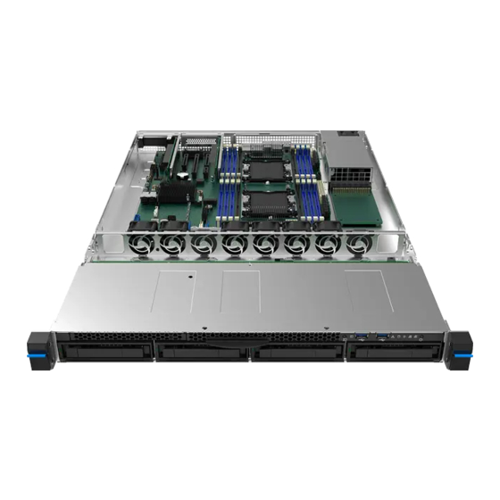
Intel® Server System M20MYP1UR System Integration and Service Guide Introduction The Intel® Server System M20MYP1UR is a 1U rack mount server system designed for performance and density and is appropriate for a range of applications from standard enterprise to cloud infrastructure environments. -
Page 13: Essential System Component Installation And Service
Intel® Server System M20MYP1UR System Integration and Service Guide Essential System Component Installation and Service This chapter provides instructions for the installation and removal of essential system components including processors, memory and storage devices. If your system has these components already integrated, you can skip this chapter and proceed to Chapter 3, “Option and Accessory Kit Integration and Service”. -
Page 14: System Top Cover Removal / Installation
Note: A non-skid surface or a stop behind the server system may be required to prevent the server system from sliding on the work surface. New systems as shipped from Intel will require a screwdriver to remove three screws on the top cover. -
Page 15: System Cover Installation
1. Place the system top cover onto the chassis and slide it towards the front of the chassis until it locks into place (see Letter A). Shipping note: When transporting the server system, Intel recommends installing the three top cover screws (See Letter B) prior to shipping. -
Page 16: Air Duct Removal
Intel® Server System M20MYP1UR System Integration and Service Guide 2.2.1 Air Duct Removal Figure 3. Air duct removal 1. Power off the system and remove the system top cover (see Section 2.1.1) 2. Ensure all the cables are clear of the air duct keep out area to avoid interference from the cables during the air duct removal. -
Page 17: Processor Assembly, Installation, And Replacement
Adequate ESD protective gear (wrist strap, ESD mat) This generation of Intel Server Systems requires that the processor be attached to the heat sink prior to installation on to the server board. The processor / heat sink assembly is referred to as the processor heat sink module, or PHM. -
Page 18: Phm Assembly
Intel® Server System M20MYP1UR System Integration and Service Guide 2.3.1 PHM Assembly Figure 6. Processor heat sink handling 1. Remove the heat sink from its packaging. To avoid damage to the heat sink, grasp it by its narrower, top and bottom edges, as shown above. -
Page 19: Figure 8. Processor Clip Assembly
Intel® Server System M20MYP1UR System Integration and Service Guide Figure 8. Processor clip assembly 6. Orient the processor, component side up, so that all alignment features (processor clip alignment keys on the clip with processor alignment notches; pin 1 indicators on processor and processor clip) match those of the carrier clip as shown in the above figure. -
Page 20: Processor Installation
2.3.2 Processor Installation The Intel® Server System M20MYP1UR supports the installation of 1 or 2 processors. For the server to be operational, at least one processor must be installed. When only one processor is installed, it must be installed in the CPU 1 socket. The installation of a processor in the CPU 2 socket is optional. However, to ensure proper airflow when the server system is operational, the CPU 2 heat sink must be installed at all times. -
Page 21: Figure 12. Plastic Processor Socket Cover Removal
Intel® Server System M20MYP1UR System Integration and Service Guide Figure 12. Plastic processor socket cover removal Remove the plastic cover from the processor socket on the server board. Hold the processor cover on both sides as shown in the above figure (see Letter A). -
Page 22: Figure 14. Correct Phm Placement
Intel® Server System M20MYP1UR System Integration and Service Guide 4. Lower the PHM onto the processor socket assembly and align the guide holes of the PHM (located on diagonal corners) to the corresponding guide pins of the processor socket as shown in the figure above. -
Page 23: Figure 15. Installing The Phm
Intel® Server System M20MYP1UR System Integration and Service Guide 6. Secure PHM to the processor socket assembly. Figure 15. Installing the PHM • Using a T30 Torx bit screwdriver, securely tighten (12 in-lbs.) each fastener in the sequence shown on the label located on the top of the heat sink. -
Page 24: Processor Replacement
Intel® Server System M20MYP1UR System Integration and Service Guide 2.3.3 Processor Replacement WARNING: Processor heat sinks can become extremely hot during normal system operation. Before attempting to remove the processor from the server board, allow the processor heat sinks to fully cool. -
Page 25: Figure 18. Phm Disassembly
Intel® Server System M20MYP1UR System Integration and Service Guide Figure 18. PHM disassembly 5. Insert the head of a flat head screwdriver in-between the heat sink and the processor clip assembly and gently twist until the bond between heat sink and the processor is broken. -
Page 26: Memory Module (Dimm) Installation And Replacement
• Anti-static wrist strap and conductive workbench pad (recommended) General Memory Population Rules: Note: For details on DIMM population rules, refer to the Intel® Server System M20MYP1UR Technical Product Specification. • Each installed processor provides six memory channels. On the Intel® Server System M20MYP1UR, memory channels for each processor are labeled A –... -
Page 27: Figure 22. System Dimm Slot Population Requirements For Thermal Compliance
Figure 22. System DIMM slot population requirements for thermal compliance On the Intel® Server System M20MYP1UR, DIMM slots A2, B1, D2 and E1 of both CPU sockets need to be populated with a DIMM or supplied DIMM blank. See Figure 22 for reference. -
Page 28: Ddr4 Dimm Installation
Intel® Server System M20MYP1UR System Integration and Service Guide 2.4.1 DDR4 DIMM Installation Figure 23. DDR4 DIMM installation 1. Locate the DIMM slots. Make sure the clips at either end of the DIMM slot(s) are pushed outward to the open position (see Letter A). -
Page 29: Drive Carrier Extraction, Installation, And Assembly
Intel® Server System M20MYP1UR System Integration and Service Guide Drive Carrier Extraction, Installation, and Assembly The server system includes four front drive bays that support 3.5” hard disk drives or SDDs with the option to support 2.5” SSDs. This section provides instructions for drive extraction from the chassis, drive installation into the chassis, and drive assembly. -
Page 30: 3.5" Hdd/Ssd Drive Assembly
Intel® Server System M20MYP1UR System Integration and Service Guide 2.5.3 3.5” HDD/SSD Drive Assembly Figure 27. 3.5" Drive carrier assembly - drive / drive blank removal 1. Remove the drive or drive blank from the carrier by holding the carrier assembly top side down in your right hand. -
Page 31: 2.5" Ssd Into A 3.5" Drive Carrier Assembly
Intel® Server System M20MYP1UR System Integration and Service Guide 2.5.4 2.5” SSD into a 3.5” Drive Carrier Assembly The 3.5” drive blank can be used as a 2.5” SSD bracket. Note: Due to degraded performance and reliability concerns, the use of the 3.5” drive blank as a 2.5” drive bracket is intended to support SSD type storage devices only. -
Page 32: Figure 31. 3.5" Drive Carrier To 2.5" Ssd Bracket - Mount Ssd To Bracket
Intel® Server System M20MYP1UR System Integration and Service Guide Figure 31. 3.5" Drive carrier to 2.5” SSD bracket – mount SSD to bracket 3. Mount and secure a 2.5” SSD to the drive bracket using two screws at the locations shown above (see letter D). -
Page 33: Figure 33. 3.5" Drive Carrier To 2.5" Ssd Bracket - Secure Ssd To Carrier
Intel® Server System M20MYP1UR System Integration and Service Guide Figure 33. 3.5" Drive carrier to 2.5” SSD bracket – secure SSD to carrier 7. Using two screws, secure the SSD to the carrier side rail (see Letter G). -
Page 34: Option And Accessory Kit Integration And Service
Intel® Server System M20MYP1UR System Integration and Service Guide Option and Accessory Kit Integration and Service This chapter provides instructions for the integration of system components within a server system that has the server board and other system components pre-installed. It includes installation instructions for supported system options and other available accessory option kits. -
Page 35: Internal Cable Routing Channels
Intel® Server System M20MYP1UR System Integration and Service Guide Internal Cable Routing Channels Cable routing within the system should be routed through the cable channels along each side of the server board as shown in the following illustration. When routing cables front-to-back, no cable should be routed through the center of the system or in the area between the system fans and the DIMM slots. -
Page 36: Pcie* Add-In Card Removal / Installation
Intel® Server System M20MYP1UR System Integration and Service Guide PCIe* Add-in Card Removal / Installation The server system supports up to two PCIe* add-in cards via two included riser card assemblies. This section provides instructions for the removal and installation of the riser card assemblies, as well as the installation and removal of an add-in card to/from the riser assembly. -
Page 37: Pcie* Add-In Card Installation Into Riser Card Bracket
Intel® Server System M20MYP1UR System Integration and Service Guide 3.2.2 PCIe* Add-in Card Installation into riser card bracket Figure 36. PCIe* add-In card installation 1. Remove the fastener screw (see Letter A) and remove the filler panel from the add-in card mounting bracket (see Letter B). -
Page 38: Riser Card Bracket Assmebly Removal
Intel® Server System M20MYP1UR System Integration and Service Guide 3.2.4 Riser Card Bracket Assmebly Removal Figure 38. Riser card bracket assembly removal 1. Disconnect all cables that may be attached to any parts of the add-in card. 2. Grasp the riser card bracket assembly with both hands and carefully lift it up to remove it from the system making sure the three mounting tabs in the back of the riser card bracket disengage from the chassis. -
Page 39: Intel® Embedded Server Raid Technology 2 (Intel® Esrt2) Raid5 Key - Installation / Removal - (Ipc Rksata4R5)
Intel® Server System M20MYP1UR System Integration and Service Guide Intel® Embedded Server RAID Technology 2 (Intel® ESRT2) RAID5 Key – Installation / Removal – (IPC RKSATA4R5) Required Tools and Supplies: • Anti-static wrist strap and conductive workbench pad (recommended) 3.3.1 Installing the Intel®... -
Page 40: Intel® Remote Management Module 4 Lite (Intel® Rmm4 Lite) Key - Installation / Removal - (Ipc Axxrmm4Lite2)
4. Remove the Intel® RMM4 Lite key from its packaging. 5. Locate the Intel® RMM4 Lite connector on the server board between the first two PCIe* slots. 6. Place the Intel® RMM4 Lite key over the connector and match the orientation of the key to that of the connector. -
Page 41: Trusted Platform Module (Tpm) Installation
Intel® Server System M20MYP1UR System Integration and Service Guide Trusted Platform Module (TPM) Installation Required Tools and Supplies: • Anti-static wrist strap and conductive workbench pad (recommended) • Flat head screwdriver or Phillips* (cross head) screwdriver (#2 bit) Figure 42. Trusted Platform Module (TPM) installation 1. -
Page 42: M.2 Ssd Installation / Removal
Intel® Server System M20MYP1UR System Integration and Service Guide M.2 SSD Installation / Removal Required Tools and Supplies: • Anti-static wrist strap and conductive workbench pad (recommended) • Phillips* (cross head) screwdriver (#2 bit) The system supports up to two PCIe*/SATA 2280 (80 mm) M.2 SSD devices in a stacked configuration secured by a bracket. -
Page 43: Installing Two M.2 Devices (Dual Configuration)
Intel® Server System M20MYP1UR System Integration and Service Guide 3.6.2 Installing Two M.2 Devices (Dual Configuration) Figure 45. Installing two M.2 SSD devices (dual configuration) 1. Power off the system and disconnect the AC power cord. 2. Remove the system top cover (see Section 2.1.1). -
Page 44: System Software Updates And Configuration
Updating the System Software Stack The system includes a software stack to operate, including a BIOS, BMC firmware, Intel ME firmware, and FRU and SDR data. A default software stack is loaded during the system manufacturing process. However, it may not be the latest available. -
Page 45: Navigating The Bios Setup Utility
Intel® Server System M20MYP1UR System Integration and Service Guide 4.2.3 Navigating the BIOS Setup Utility The BIOS Setup Utility consists of several menu screens, each holding either informational fields and/or configurable system setup options. The bottom right portion of each menu screen provides a list of commands that are used to navigate through the Setup utility. - Page 46 Intel® Server System M20MYP1UR System Integration and Service Guide Option Description Pressing the <F9> key causes the following to display: Load Optimized Defaults? Setup Defaults <F9> If “Yes” is highlighted and <Enter> is pressed, all Setup fields are set to their default values.
-
Page 47: System Packaging Assembly
Intel® Server System M20MYP1UR System Integration and Service Guide System Packaging Assembly The original Intel packaging, in which the server system is delivered, is designed to provide protection to a fully configured system and was tested to meet ISTA (International Safe Transit Association) Test Procedure 3A (2008). - Page 48 Intel® Server System M20MYP1UR System Integration and Service Guide 1. Place two foam inserts into the inner box as shown noting foam insert orientation. 2. Carefully wrap the system with the red EPE sheet and tape it.
- Page 49 Intel® Server System M20MYP1UR System Integration and Service Guide 3. Carefully place the system into the shipping bag and tape the bag shut. 4. Carefully lower the system into the inner shipping box as shown.
- Page 50 Intel® Server System M20MYP1UR System Integration and Service Guide 5. Place the two top foam inserts on top of the system and place a packed heatsink on each. 6. Place the processor clips and other accessories in the rear top foam insert.
- Page 51 Intel® Server System M20MYP1UR System Integration and Service Guide 9. Fold the top flaps of the outer box, end flaps first, followed by the side flaps. 10. Tape the outer box using an H-pattern, across the center first, followed by both ends.
-
Page 52: System Service - System Features Overview
See Appendix G for related documents containing additional information of this product. System Feature Reference Diagrams This section provides a high-level overview of the Intel® Server System M20MYP1UR. It provides illustrations and diagrams showing the location of important components, features, and connections found throughout the server system. -
Page 53: Control Panel Features
Intel® Server System M20MYP1UR System Integration and Service Guide 6.1.2 Control Panel Features Figure 49. Control panel features 6.1.3 Back Panel Features Figure 50. Back panel features Figure 51. Power distribution board connectors... -
Page 54: Server Board Features
Intel® Server System M20MYP1UR System Integration and Service Guide 6.1.4 Server Board Features Figure 52. Server board feature identification... -
Page 55: Figure 53. Intel® Light-Guided Diagnostic Leds - Server Board
Intel® Server System M20MYP1UR System Integration and Service Guide Figure 53. Intel® Light-Guided Diagnostic LEDs - server board... -
Page 56: Figure 54. Dimm Fault Leds
Intel® Server System M20MYP1UR System Integration and Service Guide Figure 54. DIMM fault LEDs... -
Page 57: System Configuration And Recovery Jumpers
Intel® Server System M20MYP1UR System Integration and Service Guide System Configuration and Recovery Jumpers Figure 55. System configuration and recovery jumpers The following sections describe how each jumper block is used. 6.2.1 BIOS Default Jumper Block This jumper resets BIOS options, configured using the <F2> BIOS Setup Utility, back to their original default factory settings. -
Page 58: Password Clear Jumper Block
2. Turn off the system. 3. Remove the AC power cord. Note: If the Intel ME FRC UPD jumper is moved with AC power applied to the system, the Intel ME will not operate properly. 4. Remove the system top cover. -
Page 59: Bmc Force Update Jumper Block
This jumper should only be used if the BMC firmware has gotten corrupted and requires re-installation. The following procedure should be followed: Note: System Update files are included in the System Update Packages (SUP) posted to Intel’s Download center web site. -
Page 60: Bios Recovery Jumper
The following procedure should be followed. Note: System Update Packages (SUP) can be downloaded from Intel’s download center web site. http://downloadcenter.intel.com 1. Download the SUP and unzip the contents, copying them to the root directory of a FAT32 formatted removable media device(USB flash drive). -
Page 61: System Service-Fru Replacement
Intel® Server System M20MYP1UR System Integration and Service Guide System Service-FRU Replacement This chapter provides instructions for the removal and installation of system components considered as field replaceable. Components within the system can only be serviced after the system has been powered off and AC power has been disconnected from the server system. -
Page 62: Replacing A Power Supply Module
Intel® Server System M20MYP1UR System Integration and Service Guide Replacing a Power Supply Module Required Tools and Supplies: • Anti-static wrist strap and conductive workbench pad (recommended) 7.1.1 Power Supply Module Removal The system MUST be powered OFF before removing the power supply module. -
Page 63: Replacing A System Fan
Anti-static wrist strap and conductive workbench pad (recommended) System fans used in the Intel Server System M20MYP1UR product are NOT hot-swappable. Warning: System fans operate at extremely high speeds. Do not attempt to replace a system fan until it has stopped completely. -
Page 64: Figure 59. System Fan Assembly Installation
Intel® Server System M20MYP1UR System Integration and Service Guide Figure 59. System fan assembly installation 5. Locate the replacement fan. 6. Install the replacement fan in the fan assembly, ensuring all rubber guides are in place and the cable is located on the side closest to the server board. -
Page 65: Replacing The System Battery
Intel® Server System M20MYP1UR System Integration and Service Guide Replacing the System Battery The battery on the server board powers the Real Time Clock for up to 10 years in the absence of power. When the battery starts to weaken, it loses voltage, and stored server settings and system clock and date settings maybe lost. -
Page 66: Replacing A Backplane
Intel® Server System M20MYP1UR System Integration and Service Guide 1. Power off the system and disconnect the AC power cord. 2. Remove the system top cover (see Section 2.1.1) 3. Locate the battery on the server board. 4. Gently press the metal clip as shown to release the battery (see Letter A). -
Page 67: Installing The Backplane
Intel® Server System M20MYP1UR System Integration and Service Guide 4. Remove all hot-swap drive carriers from the front drive bays, regardless of whether a drive is installed in the carrier (see section 2.5.1). 5. Disconnect all cables from the backplane. -
Page 68: Replacing The Server Board
Remove the air duct (see Section 2.2.1). Disconnect all cables attached to PCIe* add-in cards (if installed). Remove all options installed onto the server board including (if installed): Intel® RAID 5 option key, Intel® RMM 4 Lite key, TPM module, and riser bracket assemblies. -
Page 69: Server Board Installation
Intel® Server System M20MYP1UR System Integration and Service Guide 7.5.2 Server Board Installation Note: Follow ESD precautions outlined at the beginning of this manual. Figure 65. Server board installation 1. Carefully move aside any cables around the chassis base to clear the area for server board placement. -
Page 70: Appendix A. Getting Help
• A searchable knowledgebase to search for product information throughout the support site If you are still unable to obtain a solution to your issue, send an email to Intel’s technical support center using the online form available at: http://www.intel.com/p/en_US/support/contactsupport Lastly, you can contact an Intel support representative using one of the support phone numbers available at: http://www.intel.com/support/feedback.htm?group=server... -
Page 71: Appendix B. System Cable Routing Diagrams
Intel® Server System M20MYP1UR System Integration and Service Guide Appendix B. System Cable Routing Diagrams Figure 66. Intel® Server System M20MYP1UR cable routing... -
Page 72: Appendix C. System Status Led Operating States And Definition
Intel® Server System M20MYP1UR System Integration and Service Guide Appendix C. System Status LED Operating States and Definition The system status LED shows the current health of the server system. The system provides two locations for this feature; one is located on the front control panel and the other is located on the back edge of the server board, viewable from the back of the system. - Page 73 Intel® Server System M20MYP1UR System Integration and Service Guide Front Rear System State BIOS Status Description Status Status LED State LED State • Critical threshold crossed – Voltage, temperature (including HSBP temp), System is input power to power supply, output current for main power rail from...
-
Page 74: Appendix D. Post Code Diagnostic Led Decoder Table
Intel® Server System M20MYP1UR System Integration and Service Guide Appendix D. POST Code Diagnostic LED Decoder Table As an aid in troubleshooting a system hang that occurs during a system POST process, the server board includes a bank of eight POST code diagnostic LEDs on the back edge of the server board. During the system boot process, Memory Reference Code (MRC) and system BIOS execute a number of memory initialization and platform configuration processes, each of which is assigned a hexadecimal POST code number. -
Page 75: Early Post Memory Initialization Mrc Diagnostic Codes
Intel® Server System M20MYP1UR System Integration and Service Guide Early POST Memory Initialization MRC Diagnostic Codes Memory initialization at the beginning of POST includes multiple functions: discovery, channel training, validation that the DIMM population is acceptable and functional, initialization of the IMC and other hardware settings, and initialization of applicable RAS configurations. -
Page 76: Table 5. Mrc Fatal Error Codes
Intel® Server System M20MYP1UR System Integration and Service Guide Should a major memory initialization error occur, preventing the system from booting with data integrity, a beep code is generated, the MRC displays a fatal error code on the diagnostic LEDs, and a system halt command is executed. -
Page 77: Bios Post Progress Codes
SEC core at power on begin Lower Upper Early CPU initialization during SEC phase. Lower Intel® Ultra Path Interconnect (Intel® UPI) RC (Fully leverage without platform change) Upper Collect info such as SBSP, boot mode, reset type, etc. Lower Upper... - Page 78 Intel® Server System M20MYP1UR System Integration and Service Guide Post Code LED 3 LED 0 (Hex) Nibble (MSB) LED 2 LED 1 (LSB) Description Upper Coherency settings Lower Upper Intel UPI initialization done Lower PEI Phase Upper PEI core Lower...
- Page 79 Intel® Server System M20MYP1UR System Integration and Service Guide Post Code LED 3 LED 0 (Hex) Nibble (MSB) LED 2 LED 1 (LSB) Description Upper DXE NB SMM initialization Lower Upper DXE SB initialization Lower Upper DXE SB SMM initialization...
- Page 80 Intel® Server System M20MYP1UR System Integration and Service Guide Post Code LED 3 LED 0 (Hex) Nibble (MSB) LED 2 LED 1 (LSB) Description Upper DXE USB start Lower Upper DXE USB reset Lower Upper DXE USB detect Lower Upper...
- Page 81 Intel® Server System M20MYP1UR System Integration and Service Guide Post Code LED 3 LED 0 (Hex) Nibble (MSB) LED 2 LED 1 (LSB) Description Upper DXE exit boot services Lower Upper RT set virtual address map begin Lower Upper DXE legacy option ROM initialization...
- Page 82 Intel® Server System M20MYP1UR System Integration and Service Guide Post Code LED 3 LED 0 (Hex) Nibble (MSB) LED 2 LED 1 (LSB) Description Upper Recovery PEIM (recovery started) Lower Upper Recovery PEIM (capsule found) Lower Upper Recovery PEIM (capsule loaded)
- Page 83 Intel® Server System M20MYP1UR System Integration and Service Guide Post Code LED 3 LED 0 (Hex) Nibble (MSB) LED 2 LED 1 (LSB) Description Upper Initialize CLTT/OLTT Lower Upper Hardware memory test and initialization Lower Upper Execute software memory initialization...
-
Page 84: Appendix E. Post Code Errors
The user needs to replace the faulty part and restart the system. Note: The POST error codes in the following table are common to all current generation Intel server platforms. Features present on a given server board/system determines which of the listed error codes are supported. - Page 85 Intel® Server System M20MYP1UR System Integration and Service Guide Error Code Error Message Action message Response 0194 Processor family mismatch detected Please use identical CPU type. Fatal Processor Intel(R) UPI link frequencies unable to 0195 Fatal synchronize 0196 Processor model mismatch detected Please use identical CPU type.
- Page 86 Intel® Server System M20MYP1UR System Integration and Service Guide Error Code Error Message Action message Response 8543 CPU1_DIMM_B1 disabled Please remove the disabled DIMM. Major 8544 CPU1_DIMM_B2 disabled Please remove the disabled DIMM. Major 8545 CPU1_DIMM_B3 disabled Please remove the disabled DIMM.
- Page 87 Intel® Server System M20MYP1UR System Integration and Service Guide Error Code Error Message Action message Response CPU1_DIMM_B3 encountered a Serial Presence 8565 Major Detection (SPD) failure CPU1_DIMM_C1 encountered a Serial Presence 8566 Major Detection (SPD) failure CPU1_DIMM_C2 encountered a Serial Presence...
- Page 88 Intel® Server System M20MYP1UR System Integration and Service Guide Error Code Error Message Action message Response CPU2_DIMM_B2 encountered a Serial Presence 857C Major Detection (SPD) failure CPU2_DIMM_B3 encountered a Serial Presence 857D Major Detection (SPD) failure CPU2_DIMM_C1 encountered a Serial Presence...
- Page 89 Intel® Server System M20MYP1UR System Integration and Service Guide Error Code Error Message Action message Response 85DF CPU2_DIMM_H3 disabled Please remove the disabled DIMM. Major CPU2_DIMM_C3 encountered a Serial Presence 85E0 Major Detection (SPD) failure CPU2_DIMM_D1 encountered a Serial Presence...
-
Page 90: Table 8. Post Error Beep Codes
Codes that are common across all Intel server boards and systems that use same generation chipset are listed in the following table. Each digit in the code is represented by a sequence of beeps whose count is... - Page 91 Intel® Server System M20MYP1UR System Integration and Service Guide Table 9. Integrated BMC beep codes Code Reason for Beep Associated Sensors VR Watchdog Timer sensor assertion VR Watchdog Timer 1-5-1-2 The system does not power on or PS Status unexpectedly power off and a power...
-
Page 92: Appendix F. Safety Information
Note: This requirement applies only to Intel® server system products released in 2019 or later. Legacy Intel® server system products (released in 2018 or earlier) provide safeguards that require no additional access restrictions. - Page 93 Intel® Server System M20MYP1UR System Integration and Service Guide WARNING: English (US) The power supply in this product contains no user-serviceable parts. There may be more than one supply in this product. Refer servicing only to qualified personnel. Do not attempt to modify or use the supplied AC power cord if it is not the exact type required.
- Page 94 Intel® Server System M20MYP1UR System Integration and Service Guide For proper cooling and airflow, always reinstall the chassis covers before turning on the system. Operating the system without the covers in place can damage system parts. To install the covers: 1.
- Page 95 Intel® Server System M20MYP1UR System Integration and Service Guide AVERTISSEMENT: Français Le bloc d'alimentation de ce produit ne contient aucune pièce pouvant être réparée par l'utilisateur. Ce produit peut contenir plus d'un bloc d'alimentation. Veuillez contacter un technicien qualifié en cas de problème.
- Page 96 Intel® Server System M20MYP1UR System Integration and Service Guide Afin de permettre le refroidissement et l’aération du système, réinstallez toujours les panneaux du boîtier avant de mettre le système sous tension. Le fonctionnement du système en l’absence des panneaux risque d’endommager ses pièces. Pour installer les panneaux, procédez comme suit:...
- Page 97 Intel® Server System M20MYP1UR System Integration and Service Guide WARNUNG: Deutsch Benutzer können am Netzgerät dieses Produkts keine Reparaturen vornehmen. Das Produkt enthält möglicherweise mehrere Netzgeräte. Wartungsarbeiten müssen von qualifizierten Technikern ausgeführt werden. Versuchen Sie nicht, das mitgelieferte Netzkabel zu ändern oder zu verwenden, wenn es sich nicht genau um den erforderlichen Typ handelt.
- Page 98 Intel® Server System M20MYP1UR System Integration and Service Guide Zur ordnungsgemäßen Kühlung und Lüftung muß die Gehäuseabdeckung immer wieder vor dem Einschalten installiert werden. Ein Betrieb des Systems ohne angebrachte Abdeckung kann Ihrem System oder Teile darin beschädigen. Um die Abdeckung wieder anzubringen: 1.
- Page 99 Intel® Server System M20MYP1UR System Integration and Service Guide AVVERTENZA: Italiano Rivolgersi ad un tecnico specializzato per la riparazione dei componenti dell'alimentazione di questo prodotto. È possibile che il prodotto disponga di più fonti di alimentazione. Non modificare o utilizzare il cavo di alimentazione in c.a. fornito dal produttore, se non corrisponde esattamente al tipo richiesto.
- Page 100 Intel® Server System M20MYP1UR System Integration and Service Guide Per il giusto flusso dell’aria e raffreddamento del sistema, rimettere sempre le coperture del telaio prima di riaccendere il sistema. Operare il sistema senza le coperture al loro proprio posto potrebbe danneggiare i componenti del sistema. Per rimettere le coperture del telaio: 1.
- Page 101 Intel® Server System M20MYP1UR System Integration and Service Guide ADVERTENCIAS: Español El usuario debe abstenerse de manipular los componentes de la fuente de alimentación de este producto, cuya reparación debe dejarse exclusivamente en manos de personal técnico especializado. Puede que este producto disponga de más de una fuente de alimentación.
- Page 102 Intel® Server System M20MYP1UR System Integration and Service Guide Para obtener un enfriamiento y un flujo de aire adecuados, reinstale siempre las tapas del chasis antes de poner en marcha el sistema. Si pone en funcionamiento el sistema sin las tapas bien colocadas puede dañar los componentes del sistema.
- Page 103 Intel® Server System M20MYP1UR System Integration and Service Guide אזהרה: עברית משתמש. ייתכן שיש יותר ממקור אספקת חשמל אספקת החשמל במוצר זה לא מכילה חלקים שניתנים לשירות על ידי .לת שירות יש לפנות רק אל אנשים המוסמכים לכך אחד במוצר זה. לקב...
- Page 104 Intel® Server System M20MYP1UR System Integration and Service Guide כת. הפעלת המערכת ללא אוויר תקינים, יש תמיד להתקין מחדש את מכסי המעטפת לפני הפעלת המער לקירור ולזרימת :להתקנת המכסים .המכסים במקומם, עלולה לגרום נזק לחלקי המערכת .יש לבדוק תחילה כדי לוודא שלא נשארו כלים או חלקים רופפים בתוך המערכת...
-
Page 105: Appendix G. Related Documents
Online Server Configurator Tool peripherals The server system has support for several software utilities that can be used to configure system parameters and aid in troubleshooting system issues. All available utilities can be downloaded from the following Intel web site: http://downloadcenter.intel.com/ Table 11. -
Page 106: Appendix H. Glossary
Intel® Server System M20MYP1UR System Integration and Service Guide Appendix H. Glossary Term Definition Advanced Configuration and Power Interface ACPI Baseboard Management Controller Basic Input/Output System BIOS Central Processing Unit Double Data Rate 4th edition DDR4 Dual In-line Memory Module...
Need help?
Do you have a question about the M20MYP1UR and is the answer not in the manual?
Questions and answers