
Related Manuals for CDA RV 1200 Series


Summary of Contents for CDA RV 1200 Series
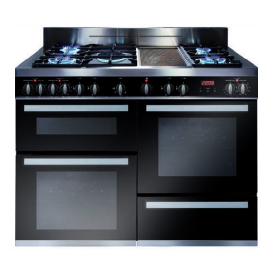
- Page 1 Dual fuel Cooker RV 1200 .. Users Operating Instructions Installation instructions Before operating this cooker, please read these instructions carefully...
- Page 2 Dear Customer Thank you for choosing one of our appliances, carefully designed and built by our specialist staff and thoroughly tested to satisfy your cooking requirements. We suggest that you read this Instruction Booklet so that you will understand fully how to operate your appliance. Please keep the booklet handy.
-
Page 3: Table Of Contents
Contents Model RV 1200 .. Page Number Introduction ..........4 Features and technical data . -
Page 4: Introduction
Introduction Congratulations on your purchase of this cooker which has been carefully designed and produced to give you many years of satisfactory use. Before using this appliance it is essential that the following instructions are carefully read and fully understood. We would emphasise that the installation section must be fully complied with for your safety to ensure that you obtain the maximum benefits from your appliance. -
Page 5: Features And Technical Data
Features and technical data Cooking hob Note: The electric ignition is incorporated in the 1. Semi-rapid burner (SR) 1,75 kW knobs. 2. Triple-ring burner (TC) 3,50 kW The appliance has a safety valve system fit- 3. Dual burner (D) 4,20 kW ted, the flow of gas will be stopped if and 4. -
Page 6: Control Panel
Control panel 12 13 Fig. 2 CONTROL PANEL - Controls description 1.Conventional oven thermostat knob (top left oven) 2. Conventional oven switch knob (top left oven) 3.Fan oven thermostat knob (bottom left oven) 4. Fan oven switch knob (bottom left oven) 5. -
Page 7: Clock And Timer With "Touch-Control" Keys
Clock and timer with “Touch-Control” keys (Right main oven only) keys – Touched simultaneously (for more than 2 seconds): setting the clock; • setting the timer volume (by • touching once, along with the “MODE” key); to cancel automatic cooking •... -
Page 8: Setting The Clock
“TOUCH-CONTROL” keys The “touch-control” keys shall be operated by the fingers (just by touching the key). When using touch controls it is best to use the ball of your finger rather than the tip. The keys are automatically deactivated: • 8 seconds after the last selection; the deactivation is indicated by an acoustic signal (“beep”). -
Page 9: Automatic Cooking
Setting the timer volume You can select from three volume levels. • Touch the “+” and “–” keys simultaneously for more than 2 seconds. • Touch the “MODE” key; you can read on the display the current timer volume (“ ton1 ”, “ ton2 ” or “ ton3 ”). •... -
Page 10: How To Use The Hob Burners
How to use the hob burners The maximum aperture position permits rapid boiling of liquids, whereas the minimum aperture position allows sim- mer warming of food or maintaining boiling conditions of liquids. To reduce the gas flow to minimum, rotate the knob further anti-clockwise to point the indicator towards the posi- tion. - Page 11 Lighting gas burners fit- ted with flame failure safety device (Semi-rapid and triple-ring burners) In order to light the burner, you must: 1 – Push and turn the knob in an anti- clockwise direction up to the position (maximum rate), push in and hold the knob until the flame has been lit (fig.
- Page 12 be adjusted from the maximum ( to the minimum ( ) position. Intermediate operating adjustments can be achieved by positioning the indicator between the maximum and minimum opening positions, and never between the maximum open- ing and position. - as a high-power burner (all flames Gas burners (Dual) produced simultaneously by inner...
- Page 13 Lighting gas burner fit- ted with flame failure safety device (Dual Burner) In order to light the burner, you must: 1 – Push and turn the knob in an anti- clockwise (fig. 5) direction up to the position (maximum rate of inner and outer crowns);...
- Page 14 Choice of burner The burner must be chosen according to the diameter of the pans and energy required. Fig. 6 Burners Pan diameter Semi-rapid 16 ÷ 24 cm Triple-ring 26 ÷ 28 cm Dual 26 ÷ 28 cm Wok pans max 36 cm do not use pans with concave or convex bases Saucepans with handles that are excessively heavy in relation to the weight of the pan...
- Page 15 Correct use of triple-ring and dual burners The flat-bottomed pans are to be placed directly onto the pan-support. To use the WOK you need to place the proper stand in order to avoid any faulty operation of the triple-ring (figs. 7a - 7b) and dual burner (figs. 8a - 8b). IMPORTANT: The wok pan stand (figs.
-
Page 16: How To Use The Ceramic Griddle
How to use the ceramic griddle Using the ceramic griddle for the first time – Remove the adhesive film which pro- tects some parts. – Remove any residual glue carefully, without using abrasive substances, to avoid scratching the surfaces. – Clean the cooking surface carefully. –... - Page 17 Cleaning the ceramic Caution! griddle The griddle becomes very hot during use and remains very hot Make sure that the ceramic griddle even after it is switched off. is switched off before cleaning it. Keep children well out of reach. –...
-
Page 18: How To Use The Multifunction Oven (Right Main Oven)
How to use the Multifunction oven (right main oven) Attention: oven door becomes very hot during opera- tion. Keep children away. General features As its name indicates, this is an oven that presents particular features from an opera- tional point of view. In fact, it is possible to insert 7 different programs to satisfy every cooking need. - Page 19 Operating principles Heating and cooking in the MULTI-FUNCTION oven are obtained in the following ways: a. by normal convection The heat is produced by the upper and lower heating elements. b. by forced convection A fan sucks in the air contained in the oven muffle, which sends it through the circular heating element and then sends it back through the muffle.
-
Page 20: Oven Light
Fig. 11 Fig. 10 Thermostat knob (Fig. 11) This only sets the cooking temperature and does not switch the oven on. Rotate clockwise until the required temperature is reached (from 50 to 250°C). Function selector knob (Fig. 10) Rotate the knob clockwise to set the oven for one of the following functions. Oven light By setting the knob to this position, only the oven light comes on. - Page 21 Grilling The infrared grill element comes on. The heat is dispersed by radiation. Use with the oven door closed and the thermostat knob between 50° and 225°C. For cooking hints, see the chapter “USE OF THE GRILL”. Recommended for: Intense grilling, browning, cooking au gratin and toasting etc. It is recommended that you do not grill for longer than 30 minutes at any one time.
- Page 22 Ventilated grill cooking The infrared grill element and the fan come on. The heat is dispersed mainly by radia- tion and the fan then distributes it all over the oven. Use with the door closed. The temperature can be regulated via the thermostat knob to between 50°...
-
Page 23: Cooking Advice
Cooking advice Sterilization Sterilization of foods to be conserved, in full and hermetically sealed jars, is done in the following way: a. Set the switch to position b. Set the thermostat knob to position 185 °C and preheat the oven. c. - Page 24 Grilling and “au gratin” Grilling may be done without the roasting jack on position of the switch, because the hot air completely envelops the food that is to be cooked. Set the thermostat to position 200°C maximum and after having preheated the oven, simply place the food on the rack.
-
Page 25: How To Use The Fan Oven (Bottom Left Oven)
How to use the Fan Oven (bottom left oven) Attention: oven door becomes very hot during opera- tion. Keep children away. General features With your new Fan oven it is possible to cook a variety of food using the 2 different cooking functions. - Page 26 Operating principles Heating and cooking in the FAN oven are obtained in the following ways: a. by forced convection A fan sucks in the air contained in the oven muffle, which sends it through the circu- lar heating element and then sends it back through the muffle. Before the hot air is sucked back again by the fan to repeat the described cycle, it envelops the food in the oven, provoking a complete and rapid cooking.
- Page 27 Function selector knob (Fig. 14) Rotate the knob clockwise to set the oven for one of the following functions. Oven light By turning the knob onto this setting we light the oven cavity. The oven remains alight while any of the functions is on. Defrosting frozen foods Only the oven fan is on.
- Page 28 Cooking advice Sterilization Sterilization of foods to be conserved, in full and hermetically sealed jars, is done in the following way: a. Set the switch to position b. Set the thermostat knob to position 185 °C and preheat the oven. c.
- Page 29 Use of the grill Preheat the oven for about 5 minutes. Introduce the food to be cooked, positioning the rack as close to the grill as possible. The dripping pan should be placed under the rack to catch the cooking juices and fats.
-
Page 30: How To Use The Conventional Oven (Top Left Oven)
How to use the Conventional Oven (top left oven) Attention: oven door becomes very hot during opera- tion. Keep children away. General features The conventional oven is equipped with 3 electrical heating elements: – 2 elements (upper and lower) for normal oven cooking –... - Page 31 Fig. 16 Fig. 15 Operating principles Heating and cooking in the CONVENTIONAL oven are obtained in the following ways: a. by normal convection The heat is produced by the upper and lower heating elements. b. by radiation The heat is radiated by the infra red grill element (use with the oven door closed). Thermostat knob (Fig.
- Page 32 Traditional convection cooking The upper and lower heating elements are switched on. The heat is diffused by natur- al convection and the temperature must be regulated between 50 and 250°C position with the thermostat knob. It is necessary to preheat the oven before introducing the foods to be cooked. Recommended for: For foods which require the same cooking temperature both internally and externally, i.
- Page 33 Grilling The infra-red heating element is switched on. The heat is diffused by radiation. Use with the oven door closed and the thermostat knob to between 50°C and 200°C. For correct use see chapter “USE OF THE GRILL” Before using the grill, preheat for about five minutes. Always grill with the oven door closed and do not use the grill for longer than 30 minutes at any one time.
-
Page 34: Do' S And Do Not' S
Do’ s and do not’ s Do’ s and do not’ s • Do always grill with the oven door closed. • Do read the user instructions carefully before using the cooker for first time. • Do allow the oven to heat for one and a half hours, before using for the first time, in order to expel any smell from the new oven insulation, without the introduction of food. -
Page 35: Important Notes
Important notes Installation, and any demonstration, information or adjustments are not included in the warranty. The cooker must be installed by a qualified person in accordance with the relevant Standards. In the UK C.O.R.G.I registered installers are authorised to undertake the installation and service work in compliance with the applicable regulations. -
Page 36: Care And Maintenance
Care and maintenance Important: As a safety measure, before you start cleaning the cooker be sure to disconnect it from the mains supply. Do not use a steam cleaner because the moisture can get into the appliance thus make it unsafe. The use of suitable protective clothing/gloves is recommended when han- dling or cleaning of this appliance. - Page 37 Enamelled parts All the enamelled parts must be cleaned with a sponge and soapy water only or other non-abrasive products. Dry preferably with a microfibre or soft cloth. Stainless steel, aluminium, painted parts and silk- screen printed surfaces Clean using an appropriate product. Always dry thoroughly. Stainless steel surfaces: can be cleaned with an appropriate stainless steel cleaner.
- Page 38 Burners They can be removed and washed with soapy water only. They will remain always perfect if cleaned with products used for silverware. After cleaning or wash, check that burner-caps and burner-heads are dry before plac- ing them in the respective housings. Note: To avoid damage to the electric ignition do not use it when the burners are not in place.
- Page 39 Triple ring burner The triple ring burner must be correctly positioned (see fig. 21); the burner rib must be enter in their logement as shown by the arrow see fig. 19). Then position the cap A and the ring B (fig. 20 - 21). The burner correctly positioned must not rotate (fig.
- Page 40 Correct position of dual burners The DUAL burner must be correctly positioned (see fig. 22); the burner rib must be fitted as shown by the arrows. Position the central small cap in its housing as shown by the arrows (fig. 23). Position the big cap in its housing as Fig.
-
Page 41: Replacing The Oven Light
Inside of ovens Every oven should always be cleaned after use when it has cooled down. The cavity should be cleaned using a mild detergent solution and warm water. Suitable proprietary chemical cleaners may be used after first consulting with the manufacturers recommendations and testing a small sample of the oven cavity. - Page 42 Assembling and removing the side racks – Assemble the wire racks to the oven walls using the 2 screws (figs. 27a - 27b). – Slide the tray and rack into the runners figs. 28a - 28b. The rack must be fitted so that the safety catch, which stops it sliding out, faces the inside of the oven.
-
Page 43: Removing The Door
Top left and right oven doors Removing the door The oven door can easily be removed Fig. 29a as follows: – Open the door to the full extent (fig. 29a). – Open the lever A completely on the left and right hinges (fig. 29b). –... - Page 44 Top left and right oven doors Cleaning the panes of glass Do not use harsh abrasive cleaners or sharp metal scrapers to clean Fig. 30 the oven door glass since they scratch the surface, which may result in shattering of the glass. Removing the inner pane of glass The oven door has two panes.
- Page 45 Replacing the inner pane of glass Make sure the door is locked open (see figs. 30, 31, 32). 2. Replace the inner pane: • Check that the four rubber pads are in place (D in Fig. 35). Fig. 35 • Check that you are holding the pane the correct way.
- Page 46 Bottom left oven door Note: The oven door should only be removed by an authorised service agent. Removal of the oven door by a non- authorised person will invalidate the guarantee. Fig. 41 Removing the inner pane of glass When removing and replacing the inner glass, the door should be held still by one person (fig.
- Page 47 Replacing the inner pane of glass To replace the inner pane of the door operate as follows: • Check that the four rubber pads are in place (D in Fig. 43). • Check that you are holding the pane the correct way. You should be able to read the wording on it as it faces you.
- Page 48 Drawer Removing the drawer (fig. 46) The drawer (fig. 46) 1. Open the drawer completely (fig. 46) comes out like a nor- 2. Move down the lever of left guide mal drawer. (fig. 47) and up the lever of right guide (fig.
-
Page 49: For The Installer
FOR THE INSTALLER Location This cooker has class “2/1” overheating protection so that it can be installed next to a cabinet. The appliance may be installed in a kitchen, Kitchen/diner or a bed sitting room, but not in a room or space containing a bath or a shower. The appliance must not be installed in a bed-sitting room of less than 20 m The appliance is designed and approved for domestic use only and should not be installed in a commercial, semi commercial or communal environment. - Page 50 If the cooker is installed adjacent to furniture which is higher than the gas hob cook- top, a gap of at least 200 mm must be left between the side of the cooker and the fur- niture. Curtains must not be fitted immediatly behind appliance or within 500 mm of the sides. It is essential that the cooker is positioned as stated in Fig.
-
Page 51: Backguard
Before installing the cooker level the appliance by screwing or unscrewing the six adjustable feet fitted below. WARNING! For safety reasons unscrew the feet (from screwed posi- tion) to the maximum extent of 5 mm (fig. 51). Fig. 51 Backguard •... -
Page 52: Moving The Cooker
Moving the cooker Warning When raising cooker to upright position always ensure two peo- ple carry out this manoeuvre to prevent damage adjustable feet (fig. 53). Warning Be carefull: do not lift the cooker Fig. 53 by the door handle when raising to the upright position (fig. -
Page 53: Provision For Ventilation
Provison for ventilation ✓ The appliance should be installed into a room or space with an air supply in accor- dance with BS 5440-2: 2000. ✓ For rooms with a volume of less than 5 m - permanent ventilation of 100 cm free area will be required. -
Page 54: Gas Installation
Gas installation IMPORTANT NOTE This appliance is supplied for use on NATURAL GAS or LPG (check the gas regulation label attached on the appliance). ✓ Appliances supplied for use on NATURAL GAS: they are adjusted for this gas only and cannot be used on any other gas (LPG) without modification. -
Page 55: Gas Connection
Gas connection The installation of the gas appliance to Natural Gas or LP Gas must be carried out by a C.O.R.G.I. registered installer. Installers shall take due account of the provisions of the relevant British Standards Code of Practice, the Gas Safety Regulations and the Building Standards (Scotland)(Consolidation) Regulations issued by the Scottish Development Department. - Page 56 Cat: II 2H3+ Gas connection The gas supply must be connected to the gas inlet which is located at the rear of the appliance (see figure 56). If the connection pipe cross the cooker, it must be positioned under the cooker rear protection.
-
Page 57: Conversion To Natural Gas Or To Lpg
Conversion to Natural Gas or to LPG Injectors replacement of Semi-rapid top burners burner Every cooker is provided with a set of injectors for the various types of gas. Injectors not supplied can be obtained from the After-Sales Service. Select the injectors to be replaced according to the table at page 59. - Page 58 Adjusting of the minimum of the top burners In the minimum position the flame must have a length of about 4 mm and must remain lit even with a quick turn from the maximum position to that of minimum. The flame adjustment is done in the follow- ing way: Semi-rapid and triple ring burners –...
-
Page 59: Lubrication Of The Gas Taps
Table for the choice of the injectors Cat: 2H3+ G 30 - 28-30 mbar G 20 Reduced Nominal G 31 - 37 mbar 20 mbar Power Power BURNERS By-pass Ø injector By-pass Ø injector [kW] [kW] [1/100 mm] [1/100 mm] [1/100 mm] [1/100 mm] Semi-rapid (SR) -
Page 60: Electrical Installation
Electrical installation For your safety please read the following information: WARNING! Before effecting any intervention on the electrical parts the appliance must be disconnected from the network. IMPORTANT: The cooker must be installed in accordance with the manufacturer’ s instructions. Incorrect installation, for which the manufacturer accepts no responsibility, may cause damage to persons, animals and things. - Page 61 Electrical feeder cable Feeder cable section connection type H05RRF To connect the feeder cable to the cooker 230 V 3 x 4 mm (**) it is necessary to: Connection with wall box connection. (**) – – Remove the 6 screws that hold shield A behind the cooker.
-
Page 62: Appliance Servicing
Appliance servicing CDA provide a quality and effective after-sales service to cover all your servicing needs. Please attach your receipt to this page for safekeeping. Please help us to help you by having the following information available when booking a service-call: 1. -
Page 63: Guarantee
CDA and the labour will be charged at the commercial rate applicable at the time of repair. - Page 64 Descriptions and illustrations in this booklet are given as simply indicative. The manufacturer reserves the right, considering the characteristics of the models described here, at any time and without notice, to make eventual necessary modifications for their construction or for commercial needs.
Need help?
Do you have a question about the RV 1200 Series and is the answer not in the manual?
Questions and answers