Table of Contents

Related Manuals for CDA RV921


Summary of Contents for CDA RV921
- Page 1 RV921 Range Cooker Manual for Installation, Use and Maintenance Customer Care Department • The Group Ltd. • Harby Road • Langar • Nottinghamshire • NG13 9HY T : 01949 862 012 F : 01949 862 003 E : service@cda.eu W : www.cda.eu...
- Page 2 Appliance information: Please enter the details on the appliance rating plate below for reference, to assist CDA Customer Care in the event of a fault with your appliance and to register your appliance for guarantee purposes. Appliance Model Serial Number...
- Page 3 CE Declarations of Conformity: This appliance has been designed, constructed and marketed in compliance with safety requirements of EEC Directive 2006/95/ EEC (Low voltage) and requirements of EMC Directive 2004/108/EEC. This appliance has been manufactured to the strictest standards and complies with all applicable legislation, including Electrical safety (LVD) and Electromagnetic interference compatibility (EMC).
-
Page 4: User Information
User Information • Read the instructions carefully before using the cooker. • Keep the instructions in a safe place for future reference. • Follow the instructions for first use (page 6). • Always use oven gloves when removing shelves and trays from the cooker. - Page 5 • This cooker has been designed for use only as a cooking appliance. Any other use (e.g. heating rooms) should be considered incorrect and therefore dangerous. • This cooker must not be installed in a bed-sit room of less than 20m³.
-
Page 6: Before First Use
Overheating can be caused by incorrect use of an oven or defective components. If an oven switches off due to overheating, wait for the oven to cool down before using it again. If the error continues, contact CDA Customer Care. -
Page 7: Before Using The Hob
Before Using The Hob • Before lighting the hob burners, check that the flame-spreaders (F) are in position with their respective burner caps (C), ensuring that the holes in the flame-spreaders are aligned with the ignition electrodes (S) and thermocouples (T) as shown in fig. 1. •... -
Page 8: Using Your Hob
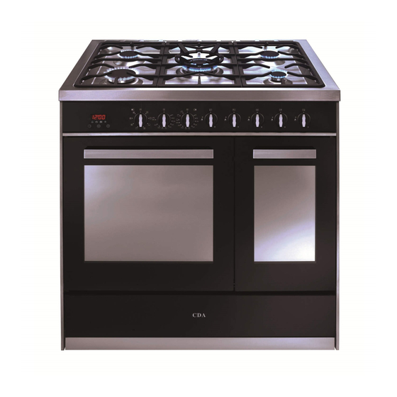
Using Your Hob Gas burners: 1. Left Rapid 3.0kW 2. Left Semi-rapid 1.75kW 3. Triple-ring/Wok 3.7kW 4. Right Semi-rapid 1.75kW 5. Right Rapid 3.0kW MAX2202001801601401201008060 Control panel: 6. Timer control 7. Left cavity function control 8. Oven temperature control 9. Right cavity function control 10. -
Page 9: Igniting The Burners
The hob can be set to the desired position by turning the control knob through the adjustment range in an anti-clockwise direction. Igniting The Burners The hob is fitted with a flame failure device. Flame failure devices operate by shutting off the supply of gas to the burner in the event that the flame is extinguished accidentally. - Page 10 Efficient Use Of Your The hob is equipped with burners of different sizes, designed to fig.4 accommodate most shapes and sizes of pan. For best results, only use pans with flat bottoms and choose an appropriate burner depending on the size of the pan.
- Page 11 Correct Use Of The Wok Pan Adaptor The wok pan adaptor is a special stand that is designed to be fitted over the triple ring burner to give support to round bottomed woks. fig.5 When using a wok, always place the wok pan adaptor in position over the pan support on the triple ring burner as shown in Fig.6.
-
Page 12: Using Your Main Oven
Using Your Main Oven Important Cooking function knob To set the function, turn the cooking function knob clockwise to the required function. Each of the oven functions uses different elements within the oven to offer you the best choice of cooking every time. These are explained below: Oven Light This function switches on the oven light without using any... - Page 13 For both grill functions please note: • Always grill with the oven door closed. • Put the grill pan as close to the grill as possible. • Do not grill for more than 30 minutes at a time. • Preheat the grill for approximately five minutes with the oven door closed.
- Page 14 Defrost Using the fan only this oven function circulates the air around the oven cavity, speeding up the natural defrost process (1kg takes approximately one hour, depending on the type of food). Fan Oven Using the circular element and the fan with a temperature between 60ºC and Max, this cooking function blows the air into and around the oven cavity.
-
Page 15: Main Oven
Programming The Main Oven Please note: • The semi-automatic and automatic cooking programmes will only work with the main oven. Cooking time indicator • The alert beep will cut off after 2 End of cooking time indicator 3 Minute minder indicator two minutes if it is not switched off 4 Current time indicator 5 Decrease key... - Page 16 • Then touch to select the required duration for the minute minder. When the correct duration shows on the display, either touch or wait for approximately five seconds. The minute minder indicator will remain lit to confirm the minute minder is on. •...
-
Page 17: Automatic Cooking
Please note: At the end of the cooking programme, remember to turn off the oven manually. Automatic cooking The main oven can be set to switch on and off automatically at preset times up to a maximum of 10 hours. To set an automatic cooking programme, follow the steps for setting a semi-automatic programme above, and then: •... - Page 18 Using Your Second Oven Control Knob To set the temperature of the second oven (conventional cooking only), or to select the other functions, turn the control knob to the required function. Each of the oven functions uses different elements within the oven to offer you the best choice of cooking every time.
- Page 19 Browning Oven Using only the top oven element pre-set at 250°C, this uses convection heat for browning and crisping. Ideal for cauliflower or macaroni cheese. Grill This function radiates the heat from the grill element. The temperature is pre-set to maximum , for efficient grilling.
-
Page 20: Cleaning The Cooker
Cleaning The Cooker IMPORTANT: Always disconnect the appliance from the power supply before undertaking any cleaning or maintenance. You should always allow the cooker to cool fully after use before undertaking any cleaning or maintenance. • Steam cleaners must not be used when cleaning this appliance •... -
Page 21: Cleaning The Oven
Over time with use, the stainless steel surface may discolour; this is normal and does not constitute a fault with this appliance. Proprietary stainless steel cleaners are available. Cleaning The Oven Interiors To clean the oven interior, suitable proprietary chemical cleaners may be used after first consulting with the manufacturer’s recommendations and testing a small sample on the oven... - Page 22 pivot the side rack back into position, pressing the top bar down to relocate it against the securing pin. Ensure that all parts are correctly replaced after cleaning before attempting to use the cooker, and that the rubber pads are in place on fig.
-
Page 23: Removing The Oven Doors
Removing The Oven Doors The oven door can easily be removed as follows: fig.10 • Open the door to the full extent (fig. 10) • Open the lever A completely on the left and right hinge (fig. 11) • Hold the door as shown in fig. 14 fig.11 •... -
Page 24: Control Knobs
Flexible Gas Pipe Check the flexible gas pipe connecting the gas supply to the cooker regularly. It must be always in perfect condition; in case of damage contact Customer Care for advice. Control Knobs Should any of the control knobs become stiff, do not use force. Contact Customer Care for advice. - Page 25 Burner size Nominal Rating Simmer Rating LPG flow rates (l/h) (kW) (kW) G30 (Butane) G31 (Propane) Semi-Rapid 1.75 Rapid Triple ring / Wok 1.25 Total rated gas input: 13.2 kW Mains electrical voltage: 230-240Vac, 50Hz Total rated electrical consumption: 4.35 kW If your cooker is not working 1.
-
Page 26: Installation
Installation The manufacturer will not be held responsible for any damage to property or injury to persons/animals resulting from incorrect installation of this appliance. We recommend you seek the help of another individual when installing this appliance to prevent damage or injury. - Page 27 If Fitting A Cooker Hood Above The Range Cooker: If a cooker hood is to be installed above the range cooker, the height of the hood above the burners must be at least 700mm (750mm is recommended). If the instructions supplied with the hood dictate that the hood must be installed at a height greater than 700mm, then that height is the minimum required.
- Page 28 Flexible Gas Pipe The flexible gas pipe must be fitted to ensure that it does not come into contact with a moving part of the housing unit (e.g. a drawer) and that there is no obstruction to the pipe. This should be installed in accordance with fig 17.
- Page 29 Gas connection This appliance is supplied with ½” BSP tapered male elbow connection (fig 18). Anti-tilt bracket/chain This appliance is supplied fitted with safety chains and wall mounted brackets to prevent it tilting forwards. These should be fitted as part of the fig.
-
Page 30: Mains Electricity Connection
Mains Electricity Connection Warning! This appliance must be earthed To connect this appliance to a UK standard mains supply, connect the bridging links between 1-2-3 for the live feed and 4-5 for the neutral feed We recommend that the appliance is connected by a qualified electrician, who is a member of the N.I.C.E.I.C. - Page 31 Release the two locks located at either side of the connector cover at the rear of the appliance. Feed the mains lead through the cable clamp to prevent accidental disconnection. Tighten the cable clamp securely and close the connector cover. Please note: •...
-
Page 32: Gas Supply Requirements
UK and Ireland. The installation must comply with the Gas Safety (installation and use) Regulations 1984. • The CDA Group Ltd is not legally able to provide any assistance in the installation of gas appliances except to Gas Safe registered installers. Any Gas Safe registered fitter requiring help must provide their name, address and registration number. - Page 33 • An isolation tap should be provided which must be accessible after installation. Ventilation All rooms require a window or equivalent (e.g. a door) which can be opened. Some rooms require a permanent vent in addition to a window (see below). This unit must not be used in a room which is less than 5m³.
-
Page 34: Natural Gas To Lpg Conversion
Natural Gas To LPG Conversion This appliance can be converted from natural gas to propane operation at a nominal inlet pressure of 37mbar, or butane operation at a nominal inlet pressure of 28/30mbar. This conversion must only be carried out by a competent person (i.e. a Gas Safe registered fitter). Instructions to fit replacement hob injectors: 1. - Page 35 2.LPG Remove the gas control knob and turn the adjustment screw at the side of the valve shaft fully clockwise. Once the above is complete, refit the fig.21 knob and verify that the burner flame is stable (the flame must not extinguish when turning the control knob rapidly between maximum and minimum position).
- Page 36 Please contact our Customer Care Department for Service on the details below Customer Care Department • The Group Ltd. • Harby Road • Langar • Nottinghamshire • NG13 9HY T : 01949 862 012 F : 01949 862 003 E : service@cda.eu W : www.cda.eu...
Need help?
Do you have a question about the RV921 and is the answer not in the manual?
Questions and answers