Table of Contents
Advertisement
Quick Links
See also:
Handbook
Before using this unit, carefully read the sections entitled: "USING THE UNIT
SAFELY" and "IMPORTANT NOTES" (p. 6–7; p. 8). These sections provide
important information concerning the proper operation of the unit. Additionally,
in order to feel assured that you have gained a good grasp of every feature
provided by your new unit, Owner's Manual should be read in its entirety. The
manual should be saved and kept on hand as a convenient reference.
Copyright © 2008 ROLAND CORPORATION
All rights reserved. No part of this publication may be reproduced in any form without
the written permission of ROLAND CORPORATION.
Owner's Manual
Advertisement
Table of Contents

Related Manuals for Edirol V-8


Summary of Contents for Edirol V-8
- Page 1 Owner’s Manual Before using this unit, carefully read the sections entitled: “USING THE UNIT SAFELY” and “IMPORTANT NOTES” (p. 6–7; p. 8). These sections provide important information concerning the proper operation of the unit. Additionally, in order to feel assured that you have gained a good grasp of every feature provided by your new unit, Owner’s Manual should be read in its entirety.
-
Page 2: Confirm The Contents Of The Package
Confirm the Contents of the Package The V-8 includes the following items. Please take a moment to confirm that all of these items have been included with the V-8. If you find that any item is missing, contact the nearest authorized EDIROL/Roland distributor in your country. -
Page 3: Main Features
Main Features ● Eight channels of video input The V-8 provides video input connectors for eight video (composite) channels and four S-video channels. Of the input channels 1–8, S-video input is available only for channels 5–8. * If S-video and video (composite) are both input to a channel 5–7, the input from the S-video connector will take priority and will be selected automatically. -
Page 4: Table Of Contents
Video Signal Flow ..................................9 Panel Descriptions...................................10 Connecting Peripheral Devices Basic Connections...................................14 Connecting the AC Adaptor ..............................15 Examples of Using the V-8 ..............................16 Basic Operation Turning the Power On/Off ...............................20 Checking the Input and Output...............................21 Outputting Images ................................21 Outputting a Preview Image ..............................22 Menu Operations..................................23... - Page 5 Saving V-8 Settings on an External MIDI Device (Bulk Dump) ....................69 Transmitting Menu Setting Data to an External MIDI Device ....................69 Restoring Data Saved on an External MIDI Device Back into the V-8 ................70 Sending the V-8’s Settings to Another V-8 ..........................71 Controlling via V-LINK ................................72...
-
Page 6: Using The Unit Safely
EDIROL/Roland Service ● Do not allow any objects (e.g., flammable material, Center, or an authorized EDIROL/Roland distributor, as coins, pins); or liquids of any kind (water, soft drinks, listed on the “Information” page. etc.) to penetrate the unit. - Page 7 Any accumulation of dust between the your retailer, the nearest EDIROL/Roland Service power plug and the power outlet can result in poor Center, or an authorized EDIROL/Roland distributor, as insulation and lead to fire. listed on the “Information” page.
-
Page 8: Important Notes
IMPORTANT NOTES Power Supply Additional Precautions ● ● Do not connect this unit to same electrical outlet that is being This unit allows you to switch images or turn video effects on/off used by an electrical appliance that is controlled by an inverter at high speed. -
Page 9: Video Signal Flow
Preview output * The preview output will also show the settings menu of the V-8 overlaid with the image (p. 23). * INPUTs 5–7 provide composite connectors and S-video connectors. If an image is being input to both connectors of the same channel, the input from the S-video connector will take priority. -
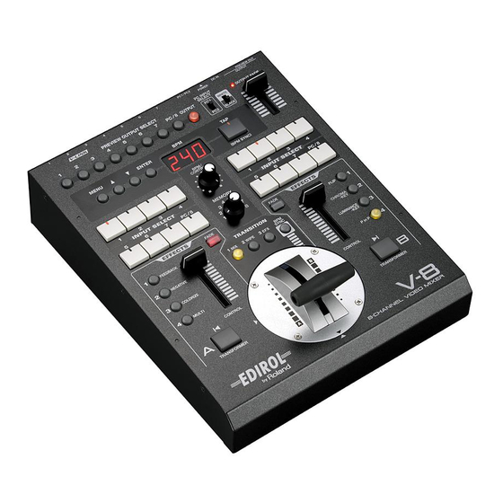
Page 10: Panel Descriptions
Panel Descriptions Operating Panel fig.top-panel1-e.eps Menu Operation Buttons [BPM/CONTROL] Knob ● These are used when working with the menu. Use this to edit the BPM value. ☞ “Operating the Menu” (p. 24) ● If you’ve used the TRANSITION buttons ( ) to select “003: ●... - Page 11 ☞ “Switching Between Two Images” (p. 35) The indicator located above the [OUTPUT FADE] fader indicates the fade status. The video fader can be installed in the V-8 in either a vertical or a horizontal orientation, and you are free to change this to suit Blinking Now fading in/out your preference.
- Page 12 Panel Descriptions (continued) Operating Panel (continued) fig.top-panel2-e.eps Bus B INPUT SELECT Buttons Bus B [CONTROL] Fader ● Use these buttons to select the image that will be input to bus B You can use this fader to control the settings of an effect of the video mixer.
-
Page 13: Rear Panel
Panel Descriptions (continued) Rear Panel fig.rear-panel-e.eps OUTPUT Connectors PREVIEW OUT Connector ● Composite output connectors This is a BNC connector that outputs the composite signal for the These are BNC connectors that output the final output image as image selected by the PREVIEW OUT SELECT buttons (p. 11). a composite video signal. -
Page 14: Connecting Peripheral Devices
If you want to connect an RCA phono type cable to a BNC connector, you’ll need to V-8 Rear panel use the included (or commercially available) RCA-BNC adaptor plugs. Ground terminal... -
Page 15: Connecting The Ac Adaptor
(continued) ● About the composite connectors and MONITOR OUT connectors The V-8’s composite inputs and outputs use BNC connectors. If your connection cables have RCA phono plugs, you’ll need to use the included (or commercially available) RCA-BNC adaptor plugs. ●... -
Page 16: Examples Of Using The V-8
(continued) Examples of Using the V-8 Events In events that involve various types of exhibition or video performance, you can use the V-8 to switch between multiple live video sources and the video from a DVD or computer. Input monitor... - Page 17 You can use the V-8’s [CONTROL] faders to dynamically apply an effect or fade to the input signal. • You can set the V-8 to Local Off, and use it to control the VJ software on your computer without affecting the output image (Panel Mode; p. 67).
- Page 18 DV camera Projector DVD player ● Advantages of using the V-8 • You can use the Picture In Picture effect to show two images simultaneously (p. 43). • You can use Luminance keying to superimpose text or graphics on an image (p. 46).
- Page 19 (V-LINK) ● Advantages of using the V-8 • By using the V-8 in conjunction with the PR-50/80 you can control live video and images from the PR-50/80 using just one device. • You can switch effects on/off from your instrument.
-
Page 20: Basic Operation
Turning the Power On/Off Turning the Power On Make sure that the V-8 is correctly connected to your other equipment. Press the [POWER] switch located on the V-8’s rear panel to turn it on. fig.power-on-e.eps V-8 Rear panel Turning the Power Off If you’ve used a menu operation (p. -
Page 21: Checking The Input And Output
Here’s how to verify that the image is being correctly output to the TV monitor or projector connected to the OUTPUT connector. Power up your connected equipment and the V-8. Play back your video device. Input the image from the video device (camera, VTR, DVD player, etc.) or computer. -
Page 22: Outputting A Preview Image
Basic Operation (continued) Outputting a Preview Image Here’s how to verify that an image is correctly output to the TV monitor connected to the PREVIEW OUT connector that you’re using for previewing. Proceed as described in steps 1–3 of “Outputting Images” (p. 21). Press the PREVIEW OUTPUT SELECT buttons to switch between preview output channels. -
Page 23: Menu Operations
Basic Operation (continued) Menu Operations By accessing menus you can make settings for the large variety of features, such as transitions and effects, that the V-8 offers. For details on the menu items, refer to “Menu List” (p. 81). Preparations for Viewing the Menu The menu is shown on the TV monitor connected to the PREVIEW OUT connector. -
Page 24: Operating The Menu
Basic Operation (continued) Operating the Menu * The “Mem2” through “Mem8” indications at the right of the menu items indicate that settings will be stored in [MEMORY] knob locations 2–8. If you want to change settings, turn the [MEMORY] knob to select the memory ☞... - Page 25 Saving your settings The content of your settings is saved in the V-8’s internal memory when you close the menu. Be aware that if you edit settings and switch off the power before closing the menu, your changes will be lost.
-
Page 26: About The Current Settings Display
Basic Operation (continued) About the Current Settings Display You can use the preview monitor to view the current settings. These settings are displayed only while the final output image is being sent to the preview output ([OUTPUT] button is lit). Settings are not displayed while channels 1–8 are being sent to the preview output. -
Page 27: Changing The Contents Of The Settings Display
Basic Operation (continued) Changing the Contents of the Settings Display Here’s how to change the contents of the information shown in the preview monitor. Press the [MENU] button to access the menu, and choose “Utility.” fig.menu-utility.eps_18 Press the [MENU] button to access the menu. Use the [ ] buttons to select “Utility.”... -
Page 28: Storing The Operating Panel Settings ([Memory] Knob)
Basic Operation (continued) Storing the Operating Panel Settings ([MEMORY] Knob) You can store the settings of the operating panel buttons and faders in memory locations 2–8 of the [MEMORY] knob. To recall the stored settings, simply choose the desired memory number. The factory preset settings are assigned to memory number 1. -
Page 29: Recalling A Memory
Basic Operation (continued) Recalling a Memory Turn the [MEMORY] knob to the memory number 1–8 that you want to recall. The settings will be recalled. fig.memory-dialset.eps * Memory number 1 contains the factory preset settings (p. 28). Copying the Contents of a Memory Here’s how to copy the settings of the currently selected memory number to a different memory number. -
Page 30: Exchanging The Contents Of Memories
Basic Operation (continued) Exchanging the Contents of Memories Here’s how to exchange the contents of the currently selected memory number with a different memory number. Turn the [MEMORY] knob to select the desired exchange-source memory number 2–8. fig.memory-dialset.eps * Memory number 1 contains the factory preset settings (p. 28). They cannot be exchanged with the settings of another memory number. -
Page 31: Fading Out The Output Image
Basic Operation (continued) Fading Out the Output Image Fading Out the Bus A / Bus B Image Here’s how to fade out the image of bus A or bus B of the video mixer. In this example we’ll show the procedure for fading out the bus A image. Press the bus A [FADE] button. -
Page 32: Fading Out The Final Output
Basic Operation (continued) Fading Out the Final Output Here’s how to fade out the final output. Set the [MEMORY] knob to memory number 1. fig.memory-dialset1.eps * The factory preset settings are assigned to memory number 1. For details on the [MEMORY] knob, refer to “Storing the Operating Panel Settings” (p. 28). Lower the [OUTPUT FADE] fader. -
Page 33: Returning The Menu Settings To The Factory-Set State (Factory Reset)
Basic Operation (continued) Returning the Menu Settings to the Factory-Set State (Factory Reset) Here’s how to return the menu settings to the factory-set state (Factory Reset). If your operations do not produce the results described in this manual, you can execute this Factory Reset operation. * All settings you’ve made will be lost when you execute a Factory Reset. -
Page 34: Returning The Settings Of A Specific Sub-Menu To The Factory-Set State
Basic Operation (continued) Returning the Settings of a Specific Sub-Menu to the Factory-Set State You can perform a factory reset on just the items of the individual sub-menu you specify: “PC Input Setup,” “PinP Setup,” “Key Setup,” “MIDI Setup,” or “Utility.” Refer to the following table, and choose “** Reset” from the sub-menu. Main menu Sub-menu PC Input Setup... -
Page 35: Switching Between Images
Switching Between Images Switching Between Two Images Here’s how to switch between the images being input to bus A and bus B of the video mixer. Set the [MEMORY] knob to memory number 1. * The factory preset settings are assigned to memory number 1. For details on the [MEMORY] knob, refer to “Storing the Operating Panel Settings”... -
Page 36: Changing The Transition Assigned To Each Transition Button
Switching Between Images (continued) Changing the Transition Assigned to Each TRANSITION Button You can change the transition effect that’s assigned to each TRANSITION button ([1 MIX] [2 WIPE] [3 EFX] buttons). Turn the [MEMORY] knob to select the memory number 2–8 whose settings you want to edit. * Memory number 1 contains the factory preset settings (p. - Page 37 About the FAM and NAM Transition Effects The transition effects built into the V-8 include FAM (Full Additive Mix) and NAM (Non-Additive Mix). Speaking simply, FAM and NAM are special dissolve transitions that compare the brightness (luminance) of two images in order to determine the degree of compositing.
-
Page 38: Combining Multiple Transition Effects (User Transition)
Switching Between Images (continued) Combining Multiple Transition Effects (User Transition) Transition effects “260: User01”–“263: User04” allow you to combine eight transition effects to create your own original transition pattern. Each of the eight transition effects are assigned to one eighth of the fader stroke. When you operate the video fader, the transition effect will change depending on the fader position. - Page 39 Switching Between Images (continued) User transition switching function You can automatically switch between the eight transitions that comprise the user transitions (p. 38) in synchronization with the BPM. When doing so, the effects will switch in the order of the Position 1–8 settings (steps 2–3 on the preceding page).
-
Page 40: Using The [Transformer] Buttons To Switch Images
Switching Between Images (continued) Using the [TRANSFORMER] Buttons to Switch Images Here’s how you can use the [TRANSFORMER] buttons to switch images without using the video fader. Set the [MEMORY] knob to memory number 1. * The factory preset settings are assigned to memory number 1. For details on the [MEMORY] knob, refer to “Storing the Operating Panel Settings”... -
Page 41: Changing The Assignment Of The [Transformer] Buttons
Switching Between Images (continued) Changing the Assignment of the [TRANSFORMER] Buttons You can change the duration or operation of the transition that occurs when you use the [TRANSFORMER] buttons to switch between images. You can also assign a TRANSITION button or EFFECTS button to a [TRANSFORMER] button, and use it to control a transition or effect. -
Page 42: Using Effects
(p. 106). Blink * The effect settings are stored in the V-8 when you turn off the effect. When you once again turn the effect on, the stored settings will be applied regardless of the position of the [CONTROL] fader. -
Page 43: Combining Two Images
Using Effects (continued) Combining Two Images You can use Picture In Picture (P in P), Chroma-key, or Luminance-key to combine the images of bus A and bus B. Using Picture In Picture (P in P) to Combine Images The image of the bus to which you apply the Picture In Picture (P in P) effect becomes the subscreen image, which will be displayed in miniature over the image of the other bus (the background image). - Page 44 Using Effects (continued) Detailed settings for the P in P effect Eight patterns (“142: PinP1”–“149: PinP8”) are provided for the P in P effect. For each one, you can specify the position and size of the subscreen. Press the [MENU] button to access the menu, and choose “PinP1 Setup”–“PinP8 Setup.” Press the [MENU] button to access the menu.
-
Page 45: Using Chroma-Key To Combine Images
Using Effects (continued) Using Chroma-Key to Combine Images When you apply chroma-key compositing to the image of a bus, the area of the key color will become transparent, and the image will be combined with the image of the other bus. Set the [MEMORY] knob to memory number 1. -
Page 46: Using Luminance-Key To Combine Images
Using Effects (continued) Using Luminance-Key to Combine Images When you apply luminance-key compositing to the image of a bus, the bright (or dark) area will become transparent, and the image will be combined with the image of the other bus. Set the [MEMORY] knob to memory number 1. - Page 47 Using Effects (continued) Detailed settings for key-compositing effects You can make detailed settings such as key color and luminance when using Chroma-key or Luminance-key to combine images. Press the [MENU] button to access the menu, and choose “Key Setup.” Press the [MENU] button to access the menu. Use the [ ] buttons to select “Key Setup.”...
-
Page 48: Changing The Color Of The Image
Using Effects (continued) Changing the Color of the Image Inverting the Image to Form a Negative You can invert the brightness and color of the image to turn it into a negative. Set the [MEMORY] knob to memory number 1. * The factory preset settings are assigned to memory number 1. -
Page 49: Adding Color According To The Brightness Or Darkness Of The Image (Colorize)
Using Effects (continued) Adding Color According to the Brightness or Darkness of the Image (Colorize) You can add color according to the brightness or darkness of the image, making the image more colorful. Set the [MEMORY] knob to memory number 1. * The factory preset settings are assigned to memory number 1. -
Page 50: Repeatedly Layering An Image Onto Itself (Feedback)
By returning the output image of a video mixer back to the input and mixing it with the original image, you can produce the effect of the image repeatedly layered with itself (Feedback). Here’s how to produce this effect on the V-8. -
Page 51: Using Multi-Screen
Using Effects (continued) Using Multi-Screen You can divide the screen horizontally and vertically to display the input image. Set the [MEMORY] knob to memory number 1. * The factory preset settings are assigned to memory number 1. For details on the [MEMORY] knob, refer to “Storing the Operating Panel Settings”... -
Page 52: Inverting The Image (Flip)
Using Effects (continued) Inverting the Image (Flip) You can invert the image between top/bottom, left/right, or top/bottom/left/right. Set the [MEMORY] knob to memory number 1. * The factory preset settings are assigned to memory number 1. For details on the [MEMORY] knob, refer to “Storing the Operating Panel Settings” (p. 28). Press a bus B INPUT SELECT button to select an image. -
Page 53: Assigning Different Effects To The Effects Buttons
Using Effects (continued) Assigning Different Effects to the EFFECTS Buttons You can change the effects that are assigned to the EFFECTS buttons. Turn the [MEMORY] knob to select the memory number 2–8 whose settings you want to edit. * Memory number 1 contains the factory preset settings (p. 28). These settings cannot be modified. -
Page 54: Editing The Input/Output Settings
Editing the Input/Output Settings Adjusting the Input Image Adjusting the PC Input Image Here’s how to make adjustments such as the brightness, color, and position of the image being input to the PC connectors. Use the [PC INPUT SELECT] switch to select either the PC1 input or PC2 input. * Input image adjustments can be made individually for the PC1 input and PC2 input. - Page 55 Editing the Input/Output Settings (continued) About the input resolution The V-8 supports the following resolutions. Resolutions 640 x 480 800 x 600 832 x 624 *1 1024 x 768 Maximum refresh rate 120 Hz 120 Hz 75 Hz 80 Hz...
-
Page 56: Adjusting The Input Image For Bus A And B
Editing the Input/Output Settings (continued) Adjusting the Input Image for Bus A and B Here’s how to adjust the brightness and color of the image that’s being input to bus A and bus B. Press the [MENU] button to access the menu, and choose “Utility.” Press the [MENU] button to access the menu. -
Page 57: Adjusting The Output Image
Editing the Input/Output Settings (continued) Adjusting the Output Image Here’s how to adjust the image that’s being output from the V-8. Press the [MENU] button to access the menu, and choose “Utility.” Press the [MENU] button to access the menu. -
Page 58: Outputting Color Bars
Editing the Input/Output Settings (continued) Outputting Color Bars Here’s how to display color bars as a convenience when adjusting your display. Press the [MENU] button to access the menu, and choose “Utility.” Press the [MENU] button to access the menu. Use the [ ] buttons to select “Utility.”... -
Page 59: Switching Between Ntsc And Pal
(continued) Switching Between NTSC and PAL The V-8’s input/output format can be switched between the NTSC format used in Japan and the United States, and the PAL format used in Europe. Choose the setting that’s appropriate for your situation. Press the [MENU] button to access the menu, and choose “Utility.”... -
Page 60: Switching Images In Synchronization With Music (Bpm Sync)
Switching Images in Synchronization with Music (BPM Sync) You can make images switch in synchronization with the beat of music. This causes the images to switch automatically without your having to operate the video fader or the [TRANSFORMER] buttons. You can specify the switching timing as a specified BPM (Beats Per Minute) or as the interval at which you press the [TAP] button. -
Page 61: Switching Images At The Tempo Specified By The [Tap] Button
Switching Images in Synchronization with Music (BPM Sync) (continued) Switching Images at the Tempo Specified by the [TAP] Button Here’s how to specify the BPM by pressing the [TAP] button at the desired interval, causing the image to switch at each beat. Set the [MEMORY] knob to memory number 1. -
Page 62: Changing The Settings Of The [Bpm Sync] Button
Switching Images in Synchronization with Music (BPM Sync) (continued) Changing the Settings of the [BPM SYNC] Button When using BPM Sync to switch images, you can make the transition effect be a cut, or make the transition occur at a multiple of the displayed BPM interval. -
Page 63: Using The V-8 With Other Equipment
MIDI Connectors MIDI messages (data handled with MIDI). On the V-8, the MIDI OUT and MIDI THRU are combined in one connector. The function is switched according to the operation being performed (p. 66). -
Page 64: Buttons And Knobs That Transmit Or Receive Midi Messages
Buttons and Knobs that Transmit or Receive MIDI Messages Operations of the V-8’s buttons and knobs can be transmitted as MIDI messages. Conversely, MIDI messages received from an external device can control the settings of the V-8’s buttons and knobs. - Page 65 Using the V-8 with Other Equipment (continued) Specifying the MIDI message assigned to a button or knob Press the [MENU] button to access the menu, and choose “MIDI Setup.” Press the [MENU] button to access the menu. Use the [ ] buttons to select “MIDI Setup.”...
-
Page 66: Midi Message Transmission Settings
Using the V-8 with Other Equipment (continued) MIDI Message Transmission Settings Specifying the MIDI message transmit channel Here’s how to specify the channel on which MIDI messages will be transmitted. Press the [MENU] button to access the menu, and choose “MIDI Setup.”... - Page 67 Turning MIDI message transmission on/off (Panel mode) Here’s how to specify whether MIDI messages will be transmitted when you operate the V-8’s buttons and knobs. Turn the [MEMORY] knob to select the memory number 2–8 that you want to edit.
-
Page 68: Midi Message Reception Settings
Using the V-8 with Other Equipment (continued) MIDI Message Reception Settings Specifying the MIDI message receive channel Here’s how to specify the channel on which MIDI messages will be received. Press the [MENU] button to access the menu, and choose “MIDI Setup.”... -
Page 69: Saving V-8 Settings On An External Midi Device (Bulk Dump)
You can transmit the V-8’s settings data to an external MIDI device (such as MIDI sequencer software) as MIDI data for storage. * Make sure that the V-8 and your MIDI device are set to the same device ID. The V-8’s device ID is specified by the “MIDI Setup” menu item “Device ID.”... -
Page 70: Restoring Data Saved On An External Midi Device Back Into The V-8
Here’s how settings saved on an external MIDI device can be restored back into the V-8. * Make sure that the V-8 and your MIDI device are set to the same device ID. The V-8’s device ID is specified by the “MIDI Setup”... -
Page 71: Sending The V-8'S Settings To Another V-8
(continued) Sending the V-8’s Settings to Another V-8 By sending the V-8’s parameter settings to another V-8 unit as MIDI data, you can put the settings of both V-8 units in the same condition. * Make sure that the transmitting V-8 and the receiving V-8 are set to the same device ID. The device ID is specified by the “MIDI Setup”... -
Page 72: Controlling Via V-Link
V-LINK compatible devices, you can easily enjoy performing a wide range of visual effects that are linked to the expressive elements of a music performance. For example, when using the V-8 in conjunction with the RSS M-400, you can use the V-8’s INPUT SELECT buttons and video fader to control the M-400’s audio input level. - Page 73 * Power up the RSS M-400, and then turn V-LINK mode on. * Make sure that the M-400 and the V-8 are set to the same device ID. The V-8’s device ID is specified by the “MIDI Setup” menu item “Device ID.”...
-
Page 74: Controlling The V-8 From An External V-Link Compatible Device (V-Link Slave)
Controlling the V-8 from an External V-LINK Compatible Device (V-LINK Slave) You can turn V-LINK mode on from a V-LINK compatible device connected to the V-8. When V-LINK mode is turned on, the V-8 can be controlled from the external device to switch the video output or image. -
Page 75: Using The V-8 In Conjunction With The Pr Series (Pr Control Mode)
In PR Control mode, you’ll be able to perform the following operations from the PR series device. ● Switch between the image being input to the V-8 and the image of the PR series simply by operating the PR series device. -
Page 76: Adjusting The Video Fader
Use a Phillips screwdriver to remove the four screws shown in the illustration. Change the orientation of the video fader. Align the triangular symbol printed on the video fader panel (circular) with the triangular symbol printed on the V-8’s panel. -
Page 77: Calibrating The Video Fader
Adjusting the Video Fader (continued) Calibrating the Video Fader Because of extended use or transportation, you may find that 100% of the image is not output even though you’ve moved the video fader all the way toward bus A or bus B. If this occurs, proceed as follows to calibrate the video fader. * You must be sure to perform the video fader calibration after installing the V-4CF crossfader (sold separately). -
Page 78: Specifying The Video Fader Operating Curve
Adjusting the Video Fader (continued) Specifying the Video Fader Operating Curve Here’s how to select the operating curve by which the video fader will switch between images. Press the [MENU] button to access the menu, and choose “Utility.” Press the [MENU] button to access the menu. Use the [ ] buttons to select “Utility.”... -
Page 79: Appendices
Troubleshooting If you suspect a malfunction, please check the following points. If this does not resolve the problem, contact a nearby EDIROL/Roland Service Center. Problems with the image output Problem Cause and Action ● The power does not turn on when Could you be using an AC adaptor other than the included one? you press the [POWER] switch. - Page 80 Could you have switched off power before closing a menu? ➔ The settings in a menu are saved in the V-8’s internal memory when you close the menu. To save the settings, edit the values as desired and then close the menu before you switch off the ☞...
-
Page 81: Menu List
Menu List Main menu Sub-menu Value (First level) (Second level) page 001: Mix01, 002: Fam01, 003: Fam✽, p. 36 1. Mix (Trans1) [Mem2]–[Mem8] 004: Nam01, 005: Nam✽, p. 99 Specifies the transition effect assigned to the [1 MIX] button 006: Wipe01–104: Wipe99, 2. - Page 82 Menu List (continued) Main menu Sub-menu Value (First level) (Second level) (The factory setting is printed in bold characters.) page [Zoom=Off, NTSC] 1–155–300 p. 54 PC Input Setup [PC1]–[PC2] Hposition [Zoom=Off, PAL] 1–222–300 Adjusts the display position in the horizontal Detailed settings for PC image input are [Zoom=On] 0–550...
- Page 83 Menu List (continued) Main menu Sub-menu Value (First level) (Second level) (The factory setting is printed in bold characters.) page 0–600 (Changes according to the p. 44 PinP1 Setup PinP-Hposi subscreen size.) Adjusts the horizontal position of the PinP2 Setup subscreen PinP3 Setup 0–207 (Changes according to the...
- Page 84 Menu List (continued) Main menu Sub-menu Value (First level) (Second level) (The factory setting is printed in bold characters.) page p. 29 Memory Edit Copy Mem ✽ -> Mem ✽ p. 30 Copy the contents of the selected memory Copies or exchanges the contents of dial setting to another number memory ✽...
- Page 85 Menu List (continued) Main menu Sub-menu Value (First level) (Second level) (The factory setting is printed in bold characters.) page Specifies the MIDI messages assigned to OFF, CC 01–CC 05, CC 07–CC 31, p. 65 MIDI Setup (continued) each button or fader CC 64–CC 95, ChAftTt, PitchBD MIDI-related settings are made here.
- Page 86 Returns the sub-menu settings to the factory- set state. Off, On p. 25 Utility Memory Protect Turns memory protect on/off Settings for the V-8 itself -48–0–+79 p. 56 Video Sync Threshold Adjusts the video input synchronization signal level -60–0–+61 VideoA Bright Adjust Adjusts the brightness of the image being input to bus A.
- Page 87 Returns the sub-menu settings to the factory- set state. NTSC, PAL p. 59 NTSC/PAL * Switches between NTSC and PAL. p. 33 Factory Reset This restores the V-8 to its original factory default settings. varies depending on the country. The factory setting...
-
Page 88: Factory Settings
Menu List (continued) Factory Settings Mem1–8 (Memory Numbers 1–8) Mem1 Mem2 Mem3 Mem4 1. Mix (Trans1) 001: Mix01 001: Mix01 001: Mix01 002: Fam01 2. Wipe (Trans2) 008: Wipe03 007: Wipe02 053: Wipe48 093: Wipe88 3. Efx (Trans3) 192: SWipe88 137: SWipe33 208: Slide01 260: User01... - Page 89 Menu List (continued) User Transition1–4 User Transition 1 User Transition2 User Transition3 User Transition4 Position1 097: Wipe94 008: Wipe05 052: Wipe49 090: Wipe87 Position2 094: Wipe91 009: Wipe06 058: Wipe55 079: Wipe76 Position3 092: Wipe89 012: Wipe09 055: Wipe52 102: Wipe99 Position4 091: Wipe88 013: Wipe10...
-
Page 90: Midi Implementation
MIDI Implementation ❍Modulation (controller numbers 1) Model: V-8 Version: 1.00 Date: Jan. 10. 2008 Status 2nd byte 3rd byte Symbol Item Setting range -------------------------------------------------------------------------------------------------------- ❍Breath-type (controller numbers 2) MIDI channel 0H - FH (ch.1 - ch.16) Status 2nd byte 3rd byte... -
Page 91: System Exclusive Messages
Device ID (dev: 00H-FH, factory setting is 10H, 7FH is details on the factory settings, refer to “Settings Transmitted/Received Using Broadcast) MIDI” (p. 96). 1st byte of model ID (V-8) 2nd byte of model ID (V-8) ■System realtime messages 3rd byte of model ID (V-8) ●Active Sensing... -
Page 92: Midi Out
* If MIDI Thru is ON, MIDI messages received at MIDI IN are re-transmitted without change from MIDI OUT. Status 2nd byte 3rd byte * If MIDI Thru is ON, messages from the V-8 itself will not be transmitted. ❍Hold 2 (controller numbers 69) ■Channel voice messages Status 2nd byte 3rd byte ●Control Change... - Page 93 (continued) 3. Parameter Address Map ■3-1. V-8 (Model ID = 00H 00H 28H) * Addresses marked by # are sent as two bytes; an upper nibble (upper 4 bits) and lower nibble (lower 4 bits). Example) If the original data is BCH, 0BH is transmitted as the first byte.
- Page 94 The next byte transmitted is 0CH. For reception, this is ignored if two bytes are not received together. * If --- is shown in the value field, the V-8 does not have a corresponding parameter. This will be ignored if received.
- Page 95 Example) If the original data is 028AH, a value of 05H is transmitted as the first byte. A value of 0AH is transmitted as the second byte. * If --- is shown in the value field, the V-8 does not have a corresponding parameter.
- Page 96 What is the decimal equivalent of 5AH? From the above table, 5AH = 90. ●MIDI Tx Channel This sets the V-8’s MIDI Transmit channel. <Example 2> What is the decimal expression of the hexadecimal The factory default setting is 1.
- Page 97 MIDI Implementation (continued) ●Input Select A Assign ●BPM SYNC Assign This controls the bus A INPUT SELECT buttons. Switches BPM SYNC on/off. The factory default setting is CC00 + CC32 + PC. With the factory settings this is unassigned. Values are 0-63 and 64-127, corresponding to OFF and ON. ●Input Select B Assign ●Transition Time Assign This controls the bus B INPUT SELECT buttons.
-
Page 98: Midi Implementation Chart
MIDI Implementation Chart Date : Jan. 10, 2008 Model: V-8 Version : 1.00 Function... Transmitted Recognized Remarks Basic Default Channel Changed 1–16 1–16 Default Mode 3 Mode 3 Mode Messages Altered *************** *************** Operational only when Note Mode Note is 49Keys Assign or Assign Mode... -
Page 99: Transition Effect List
Transition Effect List Dissolve Transition The effect gradually blends the image into another. 001: Mix01 002: Fam01 003: Fam✽ 004: Nam01 * For details on the effects, refer to “About the FAM and NAM Transition Effects” (p. 37). 005: Nam✽ Wipe Transition The effect like windshield wiper on a car. - Page 100 Transition Effect List (continued) 048: Wipe43 049: Wipe44 050: Wipe45 051: Wipe46 052: Wipe47 053: Wipe48 054: Wipe49 055: Wipe50 056: Wipe51 057: Wipe52 058: Wipe53 059: Wipe54 060: Wipe55 061: Wipe56 062: Wipe57 063: Wipe58 064: Wipe59 065: Wipe60 066: Wipe61 067: Wipe62 068: Wipe63...
- Page 101 Transition Effect List (continued) Soft Edge Type 105: SWipe01 106: SWipe02 107: SWipe03 108: SWipe04 109: SWipe05 110: SWipe06 111: SWipe07 112: SWipe08 113: SWipe09 114: SWipe10 115: SWipe11 116: SWipe12 117: SWipe13 118: SWipe14 119: SWipe15 120: SWipe16 121: SWipe17 122: SWipe18 123: SWipe19 124: SWipe20...
- Page 102 Transition Effect List (continued) 165: SWipe61 166: SWipe62 167: SWipe63 168: SWipe64 169: SWipe65 170: SWipe66 171: SWipe67 172: SWipe68 173: SWipe69 174: SWipe70 175: SWipe71 176: SWipe72 177: SWipe73 178: SWipe74 179: SWipe75 180: SWipe76 181: SWipe77 182: SWipe78 183: SWipe79 184: SWipe80 185: SWipe81...
- Page 103 Transition Effect List (continued) Slide Transition The effect to slide out the present image and slide in the another. Normal Type 208: Slide01 209: Slide02 210: Slide03 211: Slide04 212: Slide05 213: Slide06 214: Slide07 215: Slide08 216: Slide09 217: Slide10 218: Slide11 219: Slide12 220: Slide13...
- Page 104 Transition Effect List (continued) Stretch Transition This transition stretches the new image across the previous image. 234: Stretch01 235: Stretch02 236: Stretch03 237: Stretch04 238: Stretch05 239: Stretch06 240: Stretch07 241: Stretch08 242: Stretch09 243: Stretch10 244: Stretch11 245: Stretch12 246: Stretch13 247: Stretch14 248: Stretch15...
-
Page 105: Effect List
Effect List Effect name Explanation Effects name Explanation 001: STILL1 Field Frieze *1 084: COLORPASS1 002: STILL2 Frame Frieze *1 Make monochrome while leaving a specific color (color pass) 091: COLORPASS8 003: STROBE1 092: COLORPASS✽ Strobe 011: STROBE9 093: W-LUMIKEY Luminance key (extract white) 012: STROBE✽... -
Page 106: Effects That Can Be Controlled By The [Control] Fader
Effect List (continued) Effects that Can Be Controlled by the [CONTROL] Fader If you’ve assigned an effect that has an “✽” (asterisk) following its effect name, you can use the [CONTROL] fader to modify the following settings. The EFFECTS button whose settings can be modified will blink (p. 42). Effect name Setting controlled by the [CONTROL] fader 012:... -
Page 107: Effects That Cannot Be Used Simultaneously
Effect List (continued) Effects that Cannot Be Used Simultaneously For effects that cannot be used simultaneously, the effect name in the information about the settings (p. 26) is shown as “- - - - - -”. ● Combinations of a transition and an effect Name of transition Effect name that cannot be used simultaneously SILHOUETTE... -
Page 108: Block Diagram
Block Diagram... -
Page 109: Main Specifications
Main Specifications V-8: 8-Channel Video Mixer Video Format Video NTSC or PAL (ITU601) PC-RGB 640x480/120 Hz, 800x600/120 Hz, 832x624/75 Hz, 1024x768/80 Hz, 1152x864/80 Hz, 1152x870/75 Hz, 1280x1024/75 Hz, 1600x1200/60 Hz (RGB VH: positive/negative logic) * VESA DMT Version 1.0 Revision 10 conform. -
Page 110: Index
Index Effects (continued) Symbols Feedback ............50 ] buttons ..........10, 24 Flip ..............52 List ..............105 Numerics Luminance key ..........46 Multi-screen ............51 1. Mix (Trans1) ............36 Negative ............48 2. Wipe (Trans2) ............. 36 Picture in picture ..........43 3. - Page 111 Index (continued) Memory Edit ............29, 30 [MEMORY] knob ..........10, 28 PAL format ............. 59 Memory Protect ............25 Panel Mode ............67 Menu [PC INPUT SELECT] switch ....11, 21, 35, 54 Adjusting the menu display position ....25 PC Input Setup ............
- Page 112 Index (continued) User transition ............38 Switching function ..........39 Video fader Calibrating ............77 Installing ............. 76 Operating curve ..........78 Operating modes ..........78 Video Fader Calibrate A .......... 77 Video Fader Calibrate B .......... 77 Video Fader Curve ..........78 Video Fader Mode ...........
-
Page 113: Information
Information Information When you need repair service, call your nearest EDIROL/Roland Service Center or authorized EDIROL/Roland distributor in your country as shown below. CZECH REP. HUNGARY CENTRAL/LATIN OCEANIA ASIA Roland East Europe Ltd. CZECH REPUBLIC AMERICA Warehouse Area ‘DEPO’ Pf.83 DISTRIBUTOR s.r.o... - Page 114 For EU Countries For China...
- Page 115 For EU Countries This product complies with the requirements of EMC Directive 2004/108/EC. For the USA FEDERAL COMMUNICATIONS COMMISSION RADIO FREQUENCY INTERFERENCE STATEMENT This equipment has been tested and found to comply with the limits for a Class B digital device, pursuant to Part 15 of the FCC Rules.
- Page 116 04903812 08-06-3N...
Need help?
Do you have a question about the V-8 and is the answer not in the manual?
Questions and answers