Table of Contents
Advertisement
OWNER'S MANUAL
Before using this unit, carefully read the sections entitled: "USING THE UNIT SAFELY"
and "IMPORTANT NOTES" (Owner's manual p. 3 - p. 5). These sections provide
important information concerning the proper operation of the unit. Additionally, in
order to feel assured that you have gained a good grasp of every feature provided by
your new unit, Owner's manual should be read in its entirety. The manual should be
saved and kept on hand as a convenient reference.
Copyright © 2004 ROLAND CORPORATION
All rights reserved. No part of this publication may be reproduced in any form
without the written permission of ROLAND CORPORATION.
Advertisement
Table of Contents

Related Manuals for Edirol V1 video mixer


Summary of Contents for Edirol V1 video mixer
- Page 1 OWNER’S MANUAL Before using this unit, carefully read the sections entitled: “USING THE UNIT SAFELY” and “IMPORTANT NOTES” (Owner’s manual p. 3 - p. 5). These sections provide important information concerning the proper operation of the unit. Additionally, in order to feel assured that you have gained a good grasp of every feature provided by your new unit, Owner’s manual should be read in its entirety.
- Page 2 IMPORTANT: THE WIRES IN THIS MAINS LEAD ARE COLOURED IN ACCORDANCE WITH THE FOLLOWING CODE. BLUE: BROWN: As the colours of the wires in the mains lead of this apparatus may not correspond with the coloured markings identifying the terminals in your plug, proceed as follows: The wire which is coloured BLUE must be connected to the terminal which is marked with the letter N or coloured BLACK.
- Page 3 USING THE UNIT SAFELY Used for instructions intended to alert the user to the risk of death or severe injury should improperly. Used for instructions intended to alert the user to the risk of injury or material damage should the unit be used improperly.
- Page 4 • Do not force the unit’s power-supply cord to share an outlet with an unreasonable number of other devices. Be especially careful when using extension cords—the total power used by all devices you have connected to the extension cord’s outlet must never exceed the power rating (watts/amperes) for the extension cord.
-
Page 5: Important Notes
IMPORTANT NOTES In addition to the items listed under “USING THE UNIT SAFELY” on p. 3 - p.4, please read and observe the following: Power Supply • Do not connect this unit to same electrical outlet that is being used by an electrical appliance that is controlled by an inverter (such as a refrigerator, washing machine, microwave oven, or air conditioner), or that contains a motor. -
Page 6: Table Of Contents
Contents Main features...7 Examples of use...8 In a concert ... 8 In a presentation ... 8 Before you begin...9 Check the included items ... 9 Panel descriptions ...10 Top panel ... 10 Rear panel ... 11 Connections ...12 Making connections ... 12 Turning the power on ...14 Turning the power off... -
Page 7: Main Features
The V-1’s MIDI connectors let you control the V-1 from a MIDI-equipped electronic musical instrument or other external MIDI device. When connected to a Roland or Edirol product that supports V-LINK, the V-1 can be remotely controlled as a V- LINK device. -
Page 8: Examples Of Use
Examples of use In a concert The V-1 is a great addition to a concert performance. You can switch between images taken from video cameras at various angles, or use the video fader to smoothly move between them. The names or profiles of performers can be combined with live video using the Superimpose feature. -
Page 9: Before You Begin
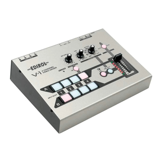
Before you begin Check the included items The V-1 is shipped with the following items. Make sure that you have all of them. fig.04-01.eps The V-1 itself AC adaptor Power cable Owner's manual... -
Page 10: Panel Descriptions
Panel descriptions Top panel fig.05-01.eps V- L I N K i n d i c a t o r ( p . 2 3 ) Indicates the status of the V-LINK connection S u p e r i m p o s e L e v e l k n o b ( p . 2 0 ) A d j u s t s t h e s u p e r i m p o s e l eve l S u p e r i m p o s e b u t t o n ( p . -
Page 11: Rear Panel
Rear panel fig.05-02.eps Video (composite) output jacks (p.12) These jacks output the video (composite) signal S-video output jack (p.12) This jack outputs the video (S-video) signal In the interest of product improvement, the specifications and/or appearance of this unit are subject to change without prior notice. MIDI OUT connector (p.24) MIDI messages are output from this connector... -
Page 12: Connections
Connections Making connections Here’s how to connect the V-1 to your video equipment. You can connect up to four video playback devices, such as a video camera, VCR, or DVD player, and take advantage of a wide range of creative possibilities. fig.06-02.eps Video playback device DVD PLAYER... - Page 13 Use the appropriate type of video cable to connect the video (composite) or S- video output jack of your video device to the V-1’s input jack. Use the appropriate type of video cable to connect the V-1’s video (composite) or S-video output jack to the input jack of your video output device (e.g., television or video projector).
-
Page 14: Turning The Power On
Turning the power on Once the connections have been completed (p. 12), turn on power to your various devices in the order specified. By turning on devices in the wrong order, you risk causing malfunction and/or damage to TV monitor and other devices. Check the power cable Make sure that the power cable from the AC adaptor is firmly plugged into the V-1. -
Page 15: Checking The Inputs And Outputs
Checking the inputs and outputs Checking the final output Here’s how to check that connections are correct. * Before you proceed, check that your video equipment is connected as described in Connections ( p. 12). Set the video fader to “A.” fig.07-01-01.eps Output an image from your video device. -
Page 16: Basic Operation
Basic operation Transitioning between video input sources Here’s how to transition (move) between video input sources. Using the video fader to switch video sources If you’re using a transition effect (Mix or Wipe), you can move between images A and B by moving the video fader up or down. If you’re using a compositing effect (Superimpose or P in P), the video fader adjusts the transparency of the composited images. -
Page 17: Using The Input Selector To Switch Video Sources
Using the input selector to switch video sources You can use the [1] through [4] buttons to switch the video source for each channel. Set the video fader to the “A” position. The green video fader indicator for “A” will light. fig.07-02-1.eps Press one of the “A”... -
Page 18: Changing The Transition Effect
Basic operation Changing the transition effect You can make use of a variety of transition effects when using the video fader or input selector to switch images. Mixing images You can smoothly mix between two images. Press the MIX button. The MIX button will light. -
Page 19: Using Compositing Effects
Using compositing effects These effects combine images “A” and “B” into a single screen. Using P in P (Picture In Picture) to composite two screens This effect layers a small image (the “foreground image”) on top of an image displayed in the full screen (the “background image”). As an example, here’s how to layer “foreground image B”... -
Page 20: Superimposing Text On The Screen
Basic operation Superimposing text on the screen Superimpose is an effect that cuts out the dark portion of an image and places it on top of a background image. Use this effect when you want to add text you created with your computer or with the P-1 (sold separately). -
Page 21: Blacking Out The Output Image
Blacking out the output image Here’s how you can temporarily black out the output image. Press the Output button. The Output button will blink; a black screen will be output, and the image will disappear. fig.07-08.eps * If you press the Output button once again, the Output button will revert to steadily lit and the output image will reappear. -
Page 22: Changing The System Settings
Changing the System settings Using Lock mode Lock mode lets you obtain a more stable image, which will prevent the image from distorting. This mode restricts operations that might cause the image to distort (such as input switching). While holding down the Superimpose button, turn on the power. The words “LOCK MODE”... -
Page 23: Using Midi To Control The V-1 From An External Device
Using V-LINK to remotely control the V-1 If the V-1 is connected to a Roland or Edirol V-LINK compatible device, you can make basic settings for controlling the V-1 simply by pressing a single button on the device to be controlled. -
Page 24: Controlling The V-1 From A Connected P-1
Using MIDI to control the V-1 from an external device Controlling the V-1 from a connected P-1 By using a connected P-1 (sold separately) to control the V-1, you can easily add still images or text to a video image. fig.09-02.eps * For details, refer to the P-1 owner’s manual. -
Page 25: Midi Implementation
MIDI implementation 1. Note Mode setting * The Note Mode setting lets you use MIDI note numbers to switch inputs. * Use a system exclusive message to set the Note Mode. * If the Note Mode is set to 49Keys Mode or Assign Mode, the velocity value of the note message will vary the transition time. -
Page 26: Additional Information
MIDI implementation 2-2-1. System Common Preference Address Parameter Name Sys.Ex.Value 10H 00H 00H V-LINK Enabled 00H - 01H 10H 00H 01H V-LINK MIDI Rx Channel 00H - 0FH (Clip) 10H 00H 02H V-LINK MIDI Rx Channel (Color) 10H 00H 03H V-LINK Note Message Enabled 00H - 03H 10H 00H 04H... - Page 27 4ch-VIDEO MIXER Model V-1 MIDI Implimentation Chart Function... Default Basic Channel Changed Default Mode Messages Altered Note Number :True Voice Note ON Velocity Note OFF Key's After Touch Ch's Pitch Bend 0,32 Control Change 1 - 5 7 - 31 64 - 95 Program Change...
-
Page 28: Troubleshooting
Troubleshooting Before you suspect a malfunction, please check the following points. If this does not resolve the problem, contact your dealer or a Roland service center. Operating the video fader does not switch between images If the same input is selected for “A” and “B,” moving the video fader won’t affect the output image. Operating the input selector does not switch between images In Lock mode, the input selector may be inoperable because of the position of the video fader. -
Page 29: Main Specifications
Main specifications Video format NTSC or PAL (ITU601) Video sampling rate 13.5 MHz 4:2:2 (Y: B-Y:R-Y) 8-bit Frame Synchronizer 2 Systems Input Level and Impedance S-video: 1 Vp-p, 75 ohms Video (composite): 1 Vp-p, 75 ohms Chrominance signal: 0.286 mVp-p, 75 ohms Output Level and Impedance S-video: 1 Vp-p, 75 ohms... - Page 31 Information When you need repair service, call your nearest EDIROL/Roland Service Center or authorized EDIROL/Roland distributor in your country as shown below. EUROPE EDIROL (Europe) Ltd. Studio 3.4 114 Power Road Deutschland London W4 5PY TEL: 0700 33 47 65 20 U.
- Page 32 03560189 ’04-3-2KS...
Need help?
Do you have a question about the V1 video mixer and is the answer not in the manual?
Questions and answers