Table of Contents
Advertisement
Quick Links
Advertisement
Table of Contents

Related Manuals for AMX MAX-CSD ENCODER


Summary of Contents for AMX MAX-CSD ENCODER
- Page 1 instruction manual MAX-CSE MAX Video Encoder...
- Page 2 RMA number. AMX Corporation is not liable for any damages caused by its products or for the failure of its products to perform. This includes any lost profits, lost savings, incidental damages, or consequential damages. AMX Corporation is not liable for any claim made by a third party or by an AMX Dealer for a third party.
-
Page 3: Table Of Contents
Table of Contents Table of Contents MAX Video Encoder ....................1 Overview ........................... 1 MAX-CSE Product Specifications ..................2 Connections and Wiring ..................5 Port Assignments and Functionality .................. 5 Wiring Guidelines - Direct Power ..................5 Wiring length guidelines ......................5 Preparing captive wires...................... - Page 4 Table of Contents Configuring Communication ................. 39 Reading the Front Panel LCD ..................39 Configuring the MAX Communication Parameters ............40 Step 1: Obtaining the unit’s initial DHCP Address ..............40 Step 2: Communicating with the unit via the browser-based UI..........40 Step 3: Assigning a Static IP Address to the unit via the browser-based UI......
- Page 5 Table of Contents NetLinx Programming ....................67 Device:Port:System (D:P:S) .................... 67 Port Assignments ......................67 MAX-CSE Only: Streaming Commands (Port 1)............. 68 RS-232/422/485 Send_Commands (Port 2) ..............73 RS-232/422/485 Send_String Escape Sequences (Port 2) ..........77 IR / Serial Ports Channels ....................78 IR/Serial Port (Port 3) Commands...................
- Page 6 Table of Contents MAX Video Encoder...
-
Page 7: Max Video Encoder
MAX Video Encoder MAX Video Encoder Overview The MAX-CSE (Commercial Solutions Encoder) allows audio and video signals to be delivered in real-time across any IP network for broadcast to a virtually limitless number of destinations – classrooms, boardrooms, training facilities, retail store branches, and other commercial settings. The MAX-CSE also provides real-time encoding of both analog audio or video content into both MPEG-2 and MPEG-4 formats for delivery across these same IP networks directly to either a MAX-CSD10 Decoder, Modero VG-Series Touch Panel, or computer (playback is enabled via a... -
Page 8: Max-Cse Product Specifications
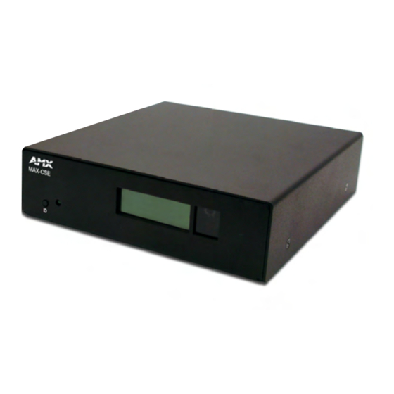
MAX Video Encoder MAX-CSE Product Specifications FIG. 1 shows the front and rear views of the MAX-CSE unit. ID button Status LED LCD Display IR Receiver (front) Composite IN Analog stereo audio S-Video IN (BNC) Microphone Ethernet Input/Output port 12 VDC Power (rear) Ethernet Speed and... - Page 9 CSE and a target Master. LCD Display: • Provides system information such as the currently used IP Address. IR Receiver: • Receives 38KHz AMX IR codes. Rear Panel Connectors: COMPOSITE IN: • BNC connector (female) supports Composite Video Input (NTSC/PAL).
- Page 10 • 4-pin 3.5 mm mini-Phoenix female I/O connector (41-5047) • BNC to RCA Adapter (41-1074) • CC-NIRC IR Emitter cable • MAX-CSE Quick Start Guide Other AMX Equipment: • AC-RK Accessory Rack Kit (FG515) • CSB Cable Support Bracket (FG517) • PMB Pole Mount Bracket (FG531) •...
-
Page 11: Connections And Wiring
Connections and Wiring Connections and Wiring Port Assignments and Functionality The rear Port Assignments are as follows: MAX-CSE Port Assignments Description ICSP Port # Video Encoder RS-232/422/485 Serial Port IR/Serial Port I/O Port IR RX Port LCD Display Wiring Guidelines - Direct Power The MAX-CSE unit requires the use of either an external 12 VDC-compliant power supply or an 802.3af-compliant device to provide DC power. -
Page 12: Wiring A Power Connection
Connections and Wiring 3. Tighten the screws to secure the wire in the connector. Do not tighten the screws excessively doing so may strip the threads and damage the connector. Wiring a power connection To use the 2-pin 3.5 mm mini-Phoenix connector with a 12 VDC-compliant power supply, the incoming PWR and GND cables from the external source must be connected to their corresponding locations on the connector (FIG. -
Page 13: Wiring The Max-Cse Connectors And Cables
Connections and Wiring Pre-configure the 802.3af-compliant PoE switch (such as the NXA-ENET24 PoE) and prepare it for power transmission to the target MAX unit. Refer to the PoE’s product documentation for more details. 802.3af-compliant PoE switch PWR + Grounded Metal plate or object GND - FIG. -
Page 14: Ethernet/Rj-45 Port: Connections And Wiring
Connections and Wiring The rear-panel wiring connections are described below (from left to right): • COMPOSITE IN: Uses a BNC connector to feed a Composite video signal in from an outside video source and then out to an external streaming media display or device via the Ethernet port. -
Page 15: Power Over Ethernet (Poe) Wiring
Connections and Wiring FIG. 5 diagrams the RJ-45 pinouts and signals for the Ethernet RJ-45 connector and cable. FIG. 5 RJ-45 wiring diagram Power over Ethernet (PoE) wiring PoE can be used to indirectly provide DC power to this 802.3af-compliant device via the unused wire pairs in the UTP or STP Ethernet cable (RJ-45 pins 4, 5, 7, and 8). -
Page 16: Db9 Device Port: Connections And Wiring
Connections and Wiring DB9 Device Port: Connections and Wiring FIG. 7 shows the connector pinouts for the rear RS-232/RS-422/RS-485 (DB9) Device Port. This port supports most standard RS-232 communication protocols for data transmission. DB9 Device Port pinouts (male connector) RS-232 RS-422 RS-485 Pin 2: RX signal... -
Page 17: Input/Output (I/O) Port: Connections And Wiring
Connections and Wiring Input/Output (I/O) Port: Connections and Wiring The I/O port responds to either switch closures, voltage level (high/low) changes, or it can be used for logic-level outputs. You can connect up to two devices on this MAX unit. FIG. - Page 18 Connections and Wiring MAX Video Encoder...
-
Page 19: Installation
Installation Installation Installing Into an Equipment Rack Use the optional AC-RK Accessory Rack Kit (FG515) to mount the MAX unit into a standard 19 inch equipment rack. 1. Discharge the static electricity from your body by touching a grounded object. 2. - Page 20 Installation MAX Video Encoder...
-
Page 21: Max-Cse Web Interface
MAX-CSE Web Interface MAX-CSE Web Interface Overview The MAX-CSE incorporates built-in security verification capabilities. By using a secured HTTP access, this device provide users with a convenient browser-based method for securing the MAX unit, and a means of configuring the parameters of the outgoing A/V stream. The browser-based User Interface (UI), used to setup the MAX unit’s configuration parameters, also enables an authorized user to either configure their own Username/Password, or utilize the factory default login profile. -
Page 22: Default Security Configuration
MAX-CSE Web Interface Default Security Configuration The Username/Password fields have been pre-populated with administrator/password as the factory default security login entries. MAX units are shipped in a secured configuration which requires the user to enter a username and password into the on-screen security dialog before gaining access to the UI pages. -
Page 23: Communicating With The Unit Via The Browser-Based Ui
MAX-CSE Web Interface Communicating with the unit via the browser-based UI 1. Launch your web browser. 2. Enter the IP Address of the target unit (as seen on the unit’s LCD display) into the web browser’s Address field (FIG. 11). 3. -
Page 24: Max -Cse User Interface Overview And Features
MAX-CSE Web Interface MAX -CSE User Interface Overview and Features User Interface Features Feature Description Browser Address field Typically located at the top of the browser window, this dynamic frame reflects the current IP Address being used by the communicating MAX device and the currently active XML UI page. - Page 25 MAX-CSE Web Interface Administration Page Features (Cont.) Feature Description Stream Status frame (Cont.): Status • Indicates the status of the outgoing stream. • Streaming indicates that the Play button has been activated and the process of converting A/V content into an outgoing media stream has begun.
-
Page 26: Administration Page
MAX-CSE Web Interface Administration Page This (FIG. 13) is the first page displayed in the Active frame after a successful login. It is accessed by clicking on the Admin link from within the Navigation frame. Current Firmware Description of the currently streamed A/V content Stream Status... - Page 27 MAX-CSE Web Interface Administration Page Features (Cont.) Feature Description Program Description: This section allows the user/administrator to enter descriptions for the currently streamed content. Program Name • A unique title associated to the currently streamed media. This title should be something recognizable to both the administrator and the target audience.
- Page 28 MAX-CSE Web Interface Administration Page Features (Cont.) Feature Description Upload Firmware: Allows a user to upload a Kit file from a known location directly onto the currently active MAX unit (shown via the UI page). • Pressing the Browse button opens a Choose File dialog which allows a user to navigate through the directory structure on the source computer and locate the new firmware Kit file.
-
Page 29: Stream Profiles Page
MAX-CSE Web Interface Stream Profiles Page To access this page, click the Stream Profiles link from within the Navigation frame. This page (FIG. 16) allows a user (with sufficient access rights) to both configure the properties of the outgoing media stream and setup the properties associated with communicating that stream to an external IP-enabled device capable of receiving and processing the data. - Page 30 MAX-CSE Web Interface If using RTP, both the Target Port and Target Audio Port must be different. When the a lower quality Encoder Profile is used (such as Standard Quality or lower), the Stream parameters default to using RTP as a Transport Protocol. This is because lower quality video uses MPEG-4 compression which must be sent via RTP.
- Page 31 MAX-CSE Web Interface Stream Profiles Page Features (Cont.) Feature Description Video: This section allows the user/administrator to define the encoding parameters for the video portion of the outgoing stream. • A drop-down list of codecs from which the user can choose the Codec (Short for enCOder/DECoder or type of MPEG video compression used for the outgoing video...
- Page 32 MAX-CSE Web Interface Stream Profiles Page Features (Cont.) Feature Description Audio: This section allows the user/administrator to define the encoding parameters for the audio portion of the outgoing stream. • A drop-down list of audio codecs from which the user can Codec (Short for enCOder/DECoder or choose the type of MPEG audio compression used for the...
- Page 33 MAX-CSE Web Interface Stream Profiles Page Features (Cont.) Feature Description Stream: This section allows the user/administrator to define the transport protocols and destination parameters for the outgoing stream content (such as IP Address and Audio/Video Ports). Transport Protocol • A drop-down list from which the user can choose between the two types of available data transfer/handling protocols.
- Page 34 MAX-CSE Web Interface Stream Profiles Page Features (Cont.) Feature Description Stream (Cont.): Target Port (video) • The port on the destination device where the outgoing video stream is being directed to. • This value can be from 0001 - 9999 (default is 5000). •...
-
Page 35: A/V Setup Page
MAX-CSE Web Interface Encoder Profiles and Parameters (Cont.) Profiles: Stream Quality: Video Defaults: Audio Defaults: Protocol Good Quality Medium • Codec: MPEG-4 • Codec: MP2 • RTP • Video In Rate: 3Mbps • Sampling Rate: 48 KHz • Resolution: D1 •... - Page 36 MAX-CSE Web Interface The following table lists the A/V Setup page features that an administrator or other authorized user can configure. A/V Setup Page Features Feature Description A/V Setup page: Provides the user with the ability to select the source of the incoming video signal (from either the rear Composite or S-Video port), the format of the incoming video (NTSC/PAL), and the gain level given to the incoming audio signal.
-
Page 37: Netlinx Settings Page
MAX-CSE Web Interface NetLinx Settings Page To access this page, click the NetLinx Settings link from within the Navigation frame. This page (FIG. 18) allows a user (with sufficient access rights) to specify which Master is to be used for communication, query, and firmware updating. - Page 38 MAX-CSE Web Interface NetLinx Settings Page Features Feature Description NetLinx Settings page: Provides the user with the ability to direct the MAX-CSE to communicate with a specific NetLinx Master. Apply • Allows a user to incorporate/save the current information to the target MAX unit.
- Page 39 MAX-CSE Web Interface NetLinx Settings Page Features (Cont.) Feature Description NetLinx Master (Cont.): Master IP/URL • Allows a user to enter the IP Address or URL used by the target Master. - This is the same IP Address used by NetLinx Studio to communicate with the Master.
-
Page 40: Ip Settings Page
MAX-CSE Web Interface IP Settings Page To access this page, click the IP Settings link from within the Navigation frame. This page (FIG. 21) allows a user (with sufficient access rights) to configure the IP communication parameters used by the MAX-CSE unit to effect a proper IP connection. FIG. - Page 41 MAX-CSE Web Interface IP Settings Page Features (Cont.) Feature Description IP Address: This section allows the user/administrator to define the communication and encryption parameters of the target Master. • These radio boxes provide the option to select from either a DHCP or Static communication mode on the MAX-CSE.
-
Page 42: User Page
MAX-CSE Web Interface FIG. 22 Setting up a Static IP connection via the IP Settings page User Page To access this page, click the User link from within the Navigation frame. This page (FIG. 23) allows a user (with sufficient access rights) to change the current access Username/Password information required for UI access. - Page 43 MAX-CSE Web Interface The following table lists the User page features that an administrator or other authorized user can configure. Refer to FIG. 24 as an example. User Page Features Feature Description User page: Provides the user with the ability to alter the current Username/ Password information required to gain entry to the UI pages and make modifications.
- Page 44 MAX-CSE Web Interface Only one User Profile is stored on the current MAX unit. FIG. 24 Setting up a new Username and Password MAX Video Encoder...
-
Page 45: Configuring Communication
3. If an update is necessary, download the latest Studio software by first logging in to www.amx.com and then navigate to Tech Center > Downloadable Files > Application Files > NetLinx Studio 2.4. This program is used to setup a System number, obtain/assign the IP/URL for the connected NetLinx Master, and transfer firmware Kit files to the Master. -
Page 46: Configuring The Max Communication Parameters
Configuring Communication Configuring the MAX Communication Parameters Although the unit is initially configured to obtain the first available DHCP Address, it is recommended that after the initial connection, the unit be setup to use a Static IP Address. Using a Static IP Address for both the source and destination devices can be beneficial for both diagnostic and direct access purposes. -
Page 47: Step 3: Assigning A Static Ip Address To The Unit Via The Browser-Based Ui
Reboot button to restart the unit and incorporate these changes. 6. Once the unit powers-up, the new Static IP Address is then displayed on the LCD after the appearance of AMX logo (which can take several minutes). MAX Video Encoder... - Page 48 Configuring Communication Browser’s Address field Navigation Active Page frame frame Stream Status frame First page displayed after login FIG. 28 Layout of the browser-based UI (User Interface) FIG. 29 Setting up a Static IP connection via the IP Settings page 7.
-
Page 49: Communicating With The Target Master Via An Ip
Network Addresses dialog to establish communication via the Ethernet- connected Master. 1. Launch NetLinx Studio 2.4 (default location is Start > Programs > AMX Control Disc > NetLinx Studio > NetLinx Studio 2.4). 2. Obtain the IP Address of the Master from your System Administrator or if you still do not have an IP Address: 3. - Page 50 Configuring Communication 8. Click the New button to open the New TCP/IP Settings dialog where you will enter both a previously obtained DHCP or Static IP Address and an associated description for the connection into their respective fields. 9. Place a checkmark within the Automatically Ping the Master Controller to ensure availability radio box to make sure the Master is initially responding online before establishing full communication.
-
Page 51: Associating The Max Unit To A Target Master
Configuring Communication Associating the MAX unit to a Target Master Although the MAX-CSE unit can function independently of a NetLinx Master, the NetLinx Settings page allows a user (with sufficient access rights) to specify which Master is to be used for communication, query, and firmware updating. - Page 52 Configuring Communication The Encryption fields on a MAX-CSE are not enabled. Therefore, to establish a connection to a target Master, both the ICSP Connectivity and Encryption requirements should be disabled from within the Master’s System Security Settings page (FIG. 33). 3.
- Page 53 Configuring Communication Use a second instance of your browser to navigate to the UI pages of the target Master (via the device’s IP Address). After successfully logging into the Master, locate the Security section of the left Navigation frame and click on the System Level link to open the System Security Settings page.
-
Page 54: Changing The Max's Device Number
Configuring Communication Changing the MAX’s Device Number The MAX unit can have its Device Address changed via either the browser-based UI, from within NetLinx Studio, or by using the front panel ID pushbutton. Changing the device number via the UI 1. -
Page 55: Recommended Netlinx Device Numbers
Configuring Communication 9. Press Done once until the Master Reboot Status field reads *Reboot of System Complete*. 10. Click the OnLine Tree tab in the Workspace window to view the devices on the System. The default System value is one (1). 11. -
Page 56: Resetting The Max Unit To A Factory Default State
Configuring Communication 3. Press the on-screen Start Identify Mode button. This action causes a previously red *Not Active* field to now display a green Waiting...Press Cancel to Quit.field. This green field indicates that Studio is waiting to detect the device value of the MAX associated with the ID button. -
Page 57: Configuration And Firmware Update
5. If an update is necessary, download the latest Studio software by first logging in to www.amx.com and then navigate to Tech Center > Downloadable Files > Application Files > NetLinx Studio 2.4. This program is used to setup a System number, obtain/assign the IP/URL for the connected NetLinx Master, and transfer firmware Kit files to the Master. -
Page 58: Upgrading Max Firmware
FIG. 37 Studio Online Tree tab showing the communicating MAX unit 4. If the MAX unit is not using the latest firmware version, follow the procedures outlined in the following sections to obtain the Kit file from www.amx.com and then transfer it to the target MAX device. -
Page 59: Upgrading The Max's Firmware - Via Netlinx Studio
PC and the target Master, verify the MAX unit appears in the OnLine Tree tab (FIG. 37) of the Workspace window. 6. Verify you have downloaded the latest MAX firmware file by first logging into ww.amx.com > Tech Center > Firmware Files and from within the MAX section of the web page locate the Encoder entry. - Page 60 Configuration and Firmware Update Description field for selected Kit file Selected MAX firmware file Firmware download status Device and System Number must match the Device and System values listed in the Workspace window FIG. 38 Send to NetLinx Device dialog (showing MAX unit’s firmware updated via IP) 11.
-
Page 61: Displaying Stream Content
Verify you have installed the latest version of TPDesign4 version 2.6 or higher on your PC. Updates are available from the www.amx.com > Tech Center > Application Files > Touch Panel Design Tools section of the website. This application is needed to create... -
Page 62: Setting Up A Modero Panel To Receive And Display A Stream
Displaying Stream Content If you enter a Target Port value of 5000, when using RTP, you must enter a value of 5002 into the Target Audio Port field. If using UDP, only the Target Port (video) field is user-definable because both the video and audio are sent out by the CSE as one stream and therefore there is no reason to define a separate audio port. -
Page 63: Step 2: Configuring The Max-Cse For Communication
Displaying Stream Content Connection Status Connection Status icon - indicates no connection to a Master Green Connection Status icon - indicates communication to a Master FIG. 39 Setup page 3. Enter 1988 into the Keypad’s password field and press Done when finished. 4. - Page 64 Displaying Stream Content 6. Determine the data throughput available on the network being used by the source encoder. This information determines which Encoder Profile and Transport Protocol will be used to encode the outgoing media stream. 7. Access Stream Profiles page (FIG. 41) by clicking the Stream Profiles link from within the Navigation frame.
- Page 65 Displaying Stream Content An RTP protocol is typically used both with lower-bandwidth streams and when user wants to purposely separate the video and audio information into two distinct streams. With this method, the Target Audio Port must be manually entered and CAN NOT be the same value as the Target Port used for video.
-
Page 66: Step 3: Configuring The Max-Cse Audio/Video Inputs
5. Click the Apply button to save the encoding profiles to the MAX-CSE. Step 4: Setup a streaming page within TPDesign4 1. Launch TPDesign4 (default location is Start > Programs > AMX Control Disc > TPDesign4 > TPDesign4). Refer to the TPDesign4 Instruction Manual for more detailed instructions of these procedures. - Page 67 Displaying Stream Content 3. From within the Step 1 dialog, enter a generic Job name and use the Panel Type drop-down arrow to choose a VG-Series panel (1200VG, 1500VG, or 1700GVG). For the purpose of these procedures, we’ve chosen to use a Job Name of Test and have selected an NXD-1700VG touch panel (FIG.
- Page 68 Displaying Stream Content Button Draw and Selection tools Currently active button Button Properties Control window (displays information for the currently active/selected button) FIG. 45 Button Properties tab FIG. 46 Video Fill - Button Properties setting 12. Use the Video Fill drop-down arrow to select the Streaming Video option (A in FIG. 46). 13.
-
Page 69: Step 5: Establishing The Final Connection Between The Two Units
Displaying Stream Content FIG. 47 Example of the current display Modero doesn’t require that an audio port be entered within the Streaming Source field because the firmware already assumes the audio port value to be 2 greater than the value set for the video port. 14. -
Page 70: Setting Up A Computer To Receive And Display A Stream
Displaying Stream Content Incoming Video signal Once done making your screen adjustments, SAVE SETTINGS. FIG. 48 Video Adjustment page (showing default values) encoding is underway) and that the unit is detecting an incoming signal (shown by the word SYNC appearing in the Video Sync section of the UI). The most common error can result from a bad cable not being detected and therefore no signal becomes available for the unit to encode. -
Page 71: Step 3: Establishing The Final Connection Between The Cse And Computer
Displaying Stream Content player because EACH signal is fed to the target computer as its own separate stream. Once instance will display the video whereas the second instance will provide the corresponding audio. 3. Enter the previously obtained IP Address of the target computer into the Target Address field. 4. - Page 72 Displaying Stream Content FIG. 49 VLC Player Adjustments (using a sample UDP stream to display both A/V in one window) Confirm that the information which was previously entered into the Stream section of the MAX’s Encoder Profiles page matches the parameters for both the target computer and target port.
-
Page 73: Netlinx Programming
NetLinx Programming NetLinx Programming You can program the MAX unit by using the commands in this section to perform a wide variety of operations using Send_Commands and variable text commands. A device must first be defined in the NetLinx programming language with values for the Device: Port: System. In these programming examples, <DEV>... -
Page 74: Max-Cse Only: Streaming Commands (Port 1)
NetLinx Programming MAX-CSE Only: Streaming Commands (Port 1) For programming purposes, do not use a hyphen when specifying MPEG functionality. Use MPEG2 and MPEG4 (no dash), do not use MPEG-2 or MPEG-4. In order for the SET commands (Set Video, Set URL, etc..) to take effect, any active stream MUST FIRST BE HALTED using the STOP command. - Page 75 NetLinx Programming MAX-CSE Streaming Send_Commands (Cont.) Command Description GET FORMAT Syntax: Get a description of the SEND_COMMAND <DEV>,"'GET FORMAT'" format used by the current Variable: incoming video signal. format = NTSC or PAL. Example: SEND_COMMAND ENCODER,"'GET FORMAT'" System response: FORMAT = NTSC Indicates that the MAX-CSE is using/expecting an incoming NTSC video format.
- Page 76 NetLinx Programming MAX-CSE Streaming Send_Commands (Cont.) Command Description GET VIDEO Requests the current configuration of the video system. The returned information includes: codec, resolution, bit rate, and mode. Get a description of the current video codec Syntax: configuration. SEND_COMMAND <DEV>,"'GET VIDEO'" Variables: codec = Off, MPEG2, or MPEG4.
- Page 77 NetLinx Programming MAX-CSE Streaming Send_Commands (Cont.) Command Description SET AUDIO The configuration parameters include: codec, sampling rate, and bit rate. Set the configuration Note: Setting the audio configuration during the 'play' state has undefined parameters for the audio results. system. Syntax: SEND_COMMAND <DEV>,"'SET AUDIO <codec>...
- Page 78 NetLinx Programming MAX-CSE Streaming Send_Commands (Cont.) Command Description SET URL The communication parameters must include: communication protocol, IP Address, and port used. Set the URL parameters for the current audio/video Syntax: stream. SEND_COMMAND <DEV>,"'SET URL <protocol> <addr> <port> [<audio port>]'" Variables: protocol = RTP or UDP.
-
Page 79: Rs-232/422/485 Send_Commands (Port 2)
NetLinx Programming MAX-CSE Streaming Send_Commands (Cont.) Command Description SET VSOURCE Sets the current video source type for the outgoing (encoded) video stream. Changing this source type redirects the video detection on the MAX unit’s rear Set the source type needed video ports. - Page 80 NetLinx Programming RS-232/422/485 Send_Commands (Cont.) Command Description CHARDM Syntax: Set the delay time between SEND_COMMAND <DEV>,"'CHARDM-<time>'" all transmitted characters to Variable: the value specified time = 0 - 255. Measured in 1 millisecond increments. (in 1 Millisecond increments). Example: SEND_COMMAND RS232_1,"'CHARDM-10'" Sets a 10-millisecond delay between all transmitted characters.
- Page 81 NetLinx Programming RS-232/422/485 Send_Commands (Cont.) Command Description RXOFF Syntax: Disable the transmission of SEND_COMMAND <DEV>,"'RXOFF'" incoming received Example: characters to the Master SEND_COMMAND RS232_1,"'RXOFF'" (default). Stops the RS232_1 device from transmitting received characters to the Master. RXON Enables sending incoming received characters to the Master. This command is automatically sent by the Master when a 'CREATE_BUFFER' program Start transmitting received instruction is executed.
- Page 82 NetLinx Programming RS-232/422/485 Send_Commands (Cont.) Command Description TSET BAUD TSET BAUD works the same as SET BAUD, except that the changes are not permanent, and the previous values will be restored if the power is cycled on Temporarily set the RS-232/ the device.
-
Page 83: Rs-232/422/485 Send_String Escape Sequences (Port 2)
NetLinx Programming RS-232/422/485 Send_String Escape Sequences (Port 2) This device also has some special SEND_STRING escape sequences: If any of the 3 character combinations below are found anywhere within a SEND_STRING program instruction, they will be treated as a command and not the literal characters. In these examples: <DEV>... -
Page 84: Ir / Serial Ports Channels
NetLinx Programming IR / Serial Ports Channels IR / Serial Ports Channels 00001 - 00229 IR commands. 00229 - 00253 May be used for system call feedback. 00254 Power Fail. (Used with the 'PON' and 'POF' commands). 00255 Power status. (Shadows I/O Link channel status). IR/Serial Port (Port 3) Commands The IR port is located at Port 3 in NetLinx D:P:S nomenclature. - Page 85 NetLinx Programming IR/Serial Send_Commands (Cont.) Command Description You can set the Pulse and Wait times with the 'CTON' and 'CTOF' commands. Halt and Clear all active or Syntax: buffered IR commands, and SEND_COMMAND <DEV>,"'CP',<code>" then send a single IR pulse. Variable: code = IR port's channel value 0 - 252 (253 - 255 reserved).
- Page 86 NetLinx Programming IR/Serial Send_Commands (Cont.) Command Description IROFF Syntax: Halt and Clear all active or SEND_COMMAND <DEV>,"'IROFF'" buffered IR commands being Example: output on the designated SEND_COMMAND IR_1,"'IROFF" port. Immediately halts and clears all IR output signals on the IR_1 port. Channel 255 changes are enabled.
- Page 87 = N (none), O (odd), E (even), M (mark), S (space). data = 7 or 8 data bits. stop = 1 and 2 stop bits. Note: AMX does not recommend using a cable longer than 10 feet (3.05 meters) for the IR Ports. Example: SEND_COMMAND IR_1,"'SET BAUD 9600,N,8,1'"...
- Page 88 NetLinx Programming IR/Serial Send_Commands (Cont.) Command Description SET MODE Sets an IR port to either IR, Serial, or Data mode. Set the IR/Serial ports for IR Note: IR DATA Mode works best when using both a lower buad rate and a or Serial-controlled devices short cable length (<...
- Page 89 NetLinx Programming IR/Serial Send_Commands (Cont.) Command Description XCHM Syntax: SEND_COMMAND <DEV>,"'XCHM <extended channel Changes the IR output pat- tern for the 'XCH' send mode>'" command. Variable: extended channel mode = 0 - 4. Example: SEND_COMMAND IR_1,"'XCHM 3'" Sets the IR_1 device's extended channel command to mode 3. Mode 0 Example (default): [x][x]<x><enter>...
-
Page 90: I/O Port Commands (Port 4)
NetLinx Programming I/O Port Commands (Port 4) The I/O port is located at Port 4 in NetLinx D:P:S nomenclature. In these examples: <DEV> = device.The I/O port supports the following commands. I/O Send Commands Command Description GET INPUT An active state can be high (logic high) or low (logic low or contact closure). Channel changes, Pushes, and Releases generate reports based on their Get the active state for the active state. -
Page 91: Lcd Commands (Port 6)
NetLinx Programming LCD Commands (Port 6) The LCD is located on the front of the unit at Port 6 in NetLinx D:P:S nomenclature. The LCD port supports the following commands. I/O Send Commands Command Description BACKLIGHT Sets the backlight level of the LCD to a specified value within a range of 0 - 100. - Page 92 ATLANTA • BOSTON • CHICAGO • CLEVELAND • DALLAS • DENVER • INDIANAPOLIS • LOS ANGELES • MINNEAPOLIS • PHILADELPHIA • PHOENIX • PORTLAND • SPOKANE • TAMPA 3000 RESEARCH DRIVE, RICHARDSON, TX 75082 USA • 800.222.0193 • 469.624.8000 • 469-624-7153 fax • 800.932.6993 technical support • www.amx.com...
Need help?
Do you have a question about the MAX-CSD ENCODER and is the answer not in the manual?
Questions and answers