
Related Manuals for AMX COLOR TOUCH PANELS WITH AUDIO (G3 FIRMWARE)


Summary of Contents for AMX COLOR TOUCH PANELS WITH AUDIO (G3 FIRMWARE)
- Page 1 instruction manual CP4/A - 4" Color Touch Panels with Audio (Firmware version G3) Tou c h Pa n els an d A cc e ss o r ie s...
- Page 2 RMA number. AMX Corporation is not liable for any damages caused by its products or for the failure of its products to perform. This includes any lost profits, lost savings, incidental damages, or consequential damages. AMX Corporation is not liable for any claim made by a third party or by an AMX Dealer for a third party.
-
Page 3: Table Of Contents
Table of Contents Table of Contents Product Information ....................1 Specifications ........................ 1 Cleaning the Touch Overlay....................5 AC-CP4A/WRB Water-Resistant Faceplate for AXD-CP4/A..........5 Specifications ........................6 Installation .........................7 Mounting the AXD Wall Mount Panels ................7 Wall Mount installation using a pre-wall CB-CP4/A Conduit Box..........7 Wall Mount panel installation into Drywall using Expansion Clips ......... - Page 4 Table of Contents Creating a Bargraph and Joystick ................... 33 Adding a bargraph or joystick button..................33 Setting Bargraph and Joystick Properties ............... 33 Setting the level code......................34 Using the Adjust Sensors Setup Page ................34 Using the Audio and IR Device Setup page..............37 External PushButtons......................
-
Page 5: Product Information
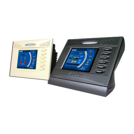
FIG. 1 Sample AXD-CP4/A and AXT-CP4/A Verify the TPDesign3 program being used is Version 3.16 build 193 or higher. The Updated EXE for TPDesign3 can be found at AMX.com > Tech Center > Downloadable Files > Application FIles > TPDesign3. Earlier versions of TPD3 will not correctly function with these panels. - Page 6 - Non-volatile via the battery backup (volatile when batteries removed) - 31 bytes are used by the firmware to store AMX configuration information. Note: If the battery is removed to clear the memory, it wipes out the AMX configuration information.
- Page 7 • Set of 18 changeable button caps consisting of: 6 blanks, 2 embossed with Up/Down arrows, and 10 pad-printed labels. These buttons match the bezel coloring. • Custom engraved buttons are available through your AMX sales representative • AXD buttons: Black set (60-5921-41BK), Beige set (60-5921-41BG), and White set (60-5921-41WH) •...
- Page 8 Programmable gain from -26dB to +34 dB in 31 steps of 2dB each. Rear Connectors: AXlink/PWR: • 4-pin 3.5 mm mini-Phoenix connector for communication to the AMX Central Controller providing both data and power Audio: • 8-pin 3.5 mm mini-Phoenix connector for audio input/output Programming Port: •...
-
Page 9: Cleaning The Touch Overlay
50% isopropyl alcohol and 50% water. AC-CP4A/WRB Water-Resistant Faceplate for AXD-CP4/A AMX now offers a new option - a set of water-resistant bezels for AXD-CP4/A touch panels: AC-CP4A/WRB (FIG. 2). The faceplate set includes all three (3) color configurations - beige, black, and white - covered with a thin transparent water-resistant film that covers the entire surface of the bezel including the touch screen, sensor lens, and pushbuttons. -
Page 10: Specifications
Product Information Specifications Specifications (Cont.) Dimensions (HWD): AC-CP4A/WRB • 4.59" x 6.13" x 0.35" (11.66 cm x 15.57 cm x 1.27 cm) Foam Insulation • Thickness: 0.125" (3.12 mm) Description: • Water- resistant faceplate for existing AXD-CP4/A touch panels. This faceplate covers the LCD and buttons. -
Page 11: Installation
Installation Installation Mounting the AXD Wall Mount Panels The following paragraphs describe mounting the touch panel directly into a drywall, solid surface, and into a Conduit Box. Wall Mount panels (AXDs) are contained within a plastic back box. This back box is not removed in either the Conduit Box (CB-CP4/A) or solid surface installation methods. - Page 12 (like a wooden beam). 3. Carefully remove the attached AMX faceplate/bezel (A in FIG. 5) from the main AXD unit (B in FIG. 5) by gripping the faceplate from the notches (located along the underside of the plate) and pulling with gentle force.
- Page 13 Installation Stud beam Attachment site for beam C - Optional CB-CP4/A conduit/wallbox Install the (4) #4-40 machine screws into into the places indicated SURFACE B - Main AXD unit consists of A - Faceplate the touch panel and backbox housing (bezel) FIG.
-
Page 14: Wall Mount Panel Installation Into Drywall Using Expansion Clips
AMX representative. 1. Carefully remove the attached AMX faceplate/bezel (A in FIG. 7 on page 11) from the main AXD unit (B in FIG. 7 on page 11) by gripping the faceplate from the notches (located along the underside of the plate) and pulling with gentle force. - Page 15 Installation Flat surface PIR, Microphone, IR and (can include a Light Sensor locations wall, podium, or other level surface) Install the 2-#6 drywall clips and screws 2 notches are (included) into the required if the unit the holes is installed into a drywall using the (2) provided clips.
- Page 16 Installation 6. Disconnect the power connector from the PSN6.5 or Central Controller until the installation is complete. 7. Insert the #6 drywall screws and clips into the two notch locations along the side edges of the Wall Mount housing as shown in both FIG. 7 on page 11 and in FIG. 8 on page 11. 8.
-
Page 17: Wall Mount Panel Installation Onto A Flat Surface Using Solid-Surface Screws
Mounting screws are secured through four (4) pre-drilled holes located at the left and right sides of the panel. 1. Carefully remove the attached AMX faceplate/bezel (A in FIG. 11) from the main AXD unit (B in FIG. 11) by gripping the faceplate from the notches (located along the underside of the plate) and pulling with gentle force. - Page 18 Installation Attachment is done along the edges of Flat/Solid surface the cutout (can include a Install the four (4) wall, podium, or solid surface screws other level into the holes surface) shown below. (screws not included) Screw length depends on the installation surface.
- Page 19 Installation Solid surface mounting screws (4) are inserted through the outer holes along the plastic housing Main AXD unit consists of internal components, CP4/A, and plastic housing FIG. 13 Screw locations for plasterboard mounting of the main AXD unit 8. Carefully insert the main unit (with surface screws) into the cutout until the rim of the AXD unit lies flush with the wall and the unit is firmly positioned.
-
Page 20: Installation Of The Ac-Cp4A/Wrb Faceplates
Installation of the AC-CP4A/WRB Faceplates AMX now offers a new option - a set of water-resistant bezels for AXD-CP4/A touch panels: AC-CP4A/WRB. This faceplate set includes all three (3) color configurations - beige, black, and white - covered with a thin transparent water-resistant film that covers the entire surface of the bezel including the touch screen, sensor lens, and pushbuttons. -
Page 21: Drywall Surface Upgrade Installation
AMX representative. 1. Carefully remove the attached AMX faceplate/bezel (A in FIG. 16) from the main AXD unit (B in FIG. 16) by gripping the faceplate from the notches (located along the underside of the plate) and pulling with gentle force. -
Page 22: Solid Surface Upgrade Installation
AMX representative. 1. Carefully remove the attached AMX faceplate/bezel (A in FIG. 17) from the main AXD unit (B in FIG. 17) by gripping the faceplate from the notches (located along the underside of the plate) and pulling with gentle force. -
Page 23: Removing The Axt Faceplate/Bezel
Installation Foam Insulation strip B - Main unit (with LCD) 4 - #4-40 solid surface screws A - Faceplate (bezel) FIG. 17 Foam insulation location on a solid surface mounted AXD 12. Make sure to align the Light, IR receiver, and PIR Motion sensor locations to their respective openings on the front bezel/faceplate. -
Page 24: Removing And Replacing Axt Pushbuttons
Installation 4. Remove all screws from the rear of the unit (B in FIG. 18 on page 19). 5. Firmly grab the front and rear of the panel and flip it back to where the entire unit is lying flat on a level surface. -
Page 25: Wiring The Touch Panel
Installation Wiring the Touch Panel The CP4/A touch panels use a 4-pin 3.5 mm mini-Phoenix AXlink connector (male) for both power and data and an 8-pin 3.5 mm mini-Phoenix connector for audio input/output (FIG. 20). This same figure shows the rear connector locations on both AXD and AXT panels. 4-pin 3.5 mm mini-Phoenix AXlink connector... -
Page 26: Wiring The Cp4/A Terminal Connectors And Cables
Installation Wiring the CP4/A terminal connectors and cables You will need a wire stripper and Phillips screwdriver to prepare and connect the captive wires. Power and Audio connectors are wired and attached to the rear of the CP4/A. FIG. 21 provides a layout of the wiring connection into both the AXD and AXT touch panels. -
Page 27: Additional Cp4/A Wiring Configurations
Installation 9. Flip the AXT panel over and place the LCD onto a soft cloth to prevent scratching during the removal process. 10. Screw the two (2) screws that attach the clip to the underside of the AXT. 11. Firmly grab the front and rear of the panel and flip it back to where the entire unit is lying flat on a level surface. - Page 28 Installation Another example used with this system is that a user, upon hearing the page, could press a button "labeled" for the source room and respond: "yes, I’m here". FIG. 23 provides a layout of the wiring connection using two directly cross-connected CP4/A panels that use a Master.
-
Page 29: Using The Cp4/A Programming Jacks
Installation Using the CP4/A Programming Jacks The programming jack (located on the side of either AXT or AXD touch panels) is used for programming/communication between the CP4/A touch panel and TPDesign3. The programming jack uses a three-wire, 2.5 mm stereo port. The optional (female to female) Axcess programming cable (FG10-727) is used to bridge the connection between the programming cables’... - Page 30 Installation 4" Color Touch Panels with Audio...
-
Page 31: Designing Touch Panel Pages
G3 Firmware Design and Reference instruction manual. Verify the TPDesign3 program being used is Version 3.16 build 193 or higher. The Updated EXE for TPDesign3 can be found at AMX.com > Tech Center > Downloadable Files > Application FIles > TPDesign3. Earlier versions of TPD3 will not correctly function with these panels. -
Page 32: Activating Edit Mode
Designing Touch Panel Pages General Button Categories (Cont.) Decision buttons Decision buttons appear when an operation has two options and requires verification before an action is performed. Status buttons Status buttons always have a dark fill with light letters and have no functionality except to display information. -
Page 33: Setting The Device Base
Designing Touch Panel Pages FIG. 26 Setup page 3. Enter (default password) in the keypad and press to open the Protected Setup 1988 ENTER page. If you press ENTER after typing an incorrect password, you are immediately returned to the previous page. 4. -
Page 34: Setting The Device Used
Designing Touch Panel Pages Edit bar FIG. 28 Main page with Edit bar Setting the Device Used Use the option in the Protected Setup page (FIG. 27) to assign a value for the DEVICE USED number of devices being controlled by the touch panel. 1. -
Page 35: Resizing A Button
Designing Touch Panel Pages Resizing a button 1. Press on the Edit bar to open the menu. BUTTON BUTTON 2. Press . Then, touch any edge of the button and drag. Removing your finger from the RESIZE panel saves the button dimensions. Defining On-Screen Button Properties External pushbuttons are configured with features similar to on-screen buttons. -
Page 36: Setting The Variable Text Code
Designing Touch Panel Pages 4. Press to open the keypad and enter a channel value of 1 - 255. The source code uses the CHAN channel code number to identify the button and its programmed operations. The channel code for non-active buttons is 0. 5. -
Page 37: Adding Text, Icons, And Bitmaps To A Button
Designing Touch Panel Pages Adding text, icons, and bitmaps to a button 1. Press on the Edit bar to open the menu. BUTTON BUTTON 2. Press to add text to the button. The operation bar appears. TEXT/IMAGE TEXT/IMAGE 3. Press any button to open the Text/Image page. 4. -
Page 38: Setting The Level Code
Designing Touch Panel Pages Setting the level code Level buttons set the device and number codes for the touch panel. Joysticks use two level numbers. The first is for the X-axis and the second for the Y-axis. You only need to specify the first level. 1. - Page 39 Designing Touch Panel Pages adjustment to the PIR activation threshold is also achieved through the use of the IRSL AXlink Send_Command. Refer to page 47 for more information. Setting the value to zero forces the value to 1. Disabling of the PIR is done by disabling both the Infrared Push/Release and the Infrared Wake features.
- Page 40 Designing Touch Panel Pages assigns a device number to the Passive Infrared sensor. An INFRARED DEVICE # adjustment to the Infrared Device value is also achieved through the use of the IRPU AXlink Send_Command. Refer to page 47 for more information. CP4/A Device numbers are also configured through TPDesign3.
-
Page 41: Using The Audio And Ir Device Setup Page
Designing Touch Panel Pages of the light sensor. The LEDs also illuminate if there is no PIR activity and the light sensor level falls below its threshold value. The order of precedence for turning Off the pushbutton LEDs is the LS then PIR. If the light sensor rises above its hysteresis (turn-on) value and there is no any activity coming from the PIR (thirty seconds of inactivity), the LEDs turn Off. -
Page 42: External Pushbuttons
Designing Touch Panel Pages assigns a device number to the speaker. Enter a device number SPEAKER DEVICE # from 1 -4 into the on-screen Keypad and press ENTER when done. assigns a level number to the speaker. Enter a level value of SPEAKER LEVEL # 1 - 8 into the on-screen Keypad and press ENTER when done. -
Page 43: Light Sensor
The CP4/A is equipped with an on-board IR receiver that is capable of receiving a one-way 38 KHz signals (of AMX codes only). The properties for this receiver is capable of being set through the Using the Adjust Sensors Setup Page section on page 34. The maximum range is 15 feet (4.57 m) for the AXT and 22 feet (6.71 m) for the AXD unit. -
Page 44: Using Tpdesign3 To Download Bitmaps, Icons, And Fonts
Designing Touch Panel Pages Page section on page 34 or via the use of commands such as MVOL AXlink Send_Command. Refer to the Using the Audio and IR Device Setup page section on page 37. Using TPDesign3 to Download Bitmaps, Icons, and Fonts TPDesign3 allows you to download bitmaps, icons, and fonts into your touch panel from an existing touch panel program. -
Page 45: Programming
Programming Programming You can program the touch panel, using the commands in this section, to perform a wide variety of operations using Axcess Send_Commands and variable text commands. Use the commands described in this section to program the touch panel. Serial Commands Serial Commands are used in the AxcessX Terminal Emulator mode. - Page 46 Programming Serial Commands (Cont.) CHECK CAL Syntax: Enters the calibra- "CHECK CAL" tion test mode. Example: CHECK CAL Begins the calibration check mode on the touch panel. ECHO ON Syntax: Turns On charac- "ECHO ON" ter echo. Example: ECHO ON The character echo is sent back to the computer.
-
Page 47: System Send_Commands
Programming Serial Commands (Cont.) Syntax: Restores the cur- "VER" rent version. Example: Returns the current version of the main firmware. WORKING? Syntax: Verifies the com- "WORKING?" munication Example: between the touch WORKING? panel and the Ter- minal Emulator. Response: $SC 1,"’CPAGE72-Main Page’" Responding touch panel turns its Main page the color white. - Page 48 Programming System Send_Commands (Cont.) AKEYB The keyboard string is set to null during power-up and stored until power-down. Opens the touch Syntax: panel keyboard “’AKEYB-<text string>’" and initializes the Variable: text string entry. text string = 0 - 59 characters Example: SEND_COMMAND TP,"’AKEYB-TOUCH HERE’"...
- Page 49 Programming System Send_Commands (Cont.) BEEP n s The Beep button in the Protected Setup page must be set from 1 - 5 for the BEEP command. The <n> and <s> are optional such that BEEP by itself enables a standard tone Gives an output of and duration.
- Page 50 Programming System Send_Commands (Cont.) CONT Syntax: Adjusts contrast of "’CONT-<level>’" display. Variable: level = 1 - 12 (1 = minimum; 12 = maximum) Example: SEND_COMMAND TP,"’CONT-12’" Sets display to highest contrast level. CLOCK Syntax: Sets the time and "’CLOCK <mm-dd-yy> <hh:mm:ss>’" date.
- Page 51 Programming System Send_Commands (Cont.) IRPU The Push/Release mode set with this command corresponds to the value present on the Adjust Sensors page. The Push/Release is disabled from the Adjust Sensors page by set- Enables/Disables ting the PIR channel number to 0 (zero). the PIR Push/ Release mode.
- Page 52 Programming System Send_Commands (Cont.) LSDM The Dim-Room mode is also set with the LIGHT DIM MODE button on the Adjust Sensors page. Enables/disables the Dim-Room Syntax: mode. "’LSDM,<n>’" Variables: n = 0, turns OFF the Dim-Room feature (disable). n = 1, turns ON the Dim-Room feature (enable). Examples: SEND_COMMAND TP,"’LSDM,0’"...
- Page 53 Programming System Send_Commands (Cont.) PBIL The button illumination features are also set using the three illumination buttons on the Adjust Sensors page. Assigns the push- button illumina- Syntax: tion modes. "’PBIL,<n>’" Variable: n = Pushbutton illumination mode value: Mode # <n> Mode Description Disabled (illumination Off) Enabled (illumination On)
- Page 54 Programming System Send_Commands (Cont.) RESET Syntax: Clears panel sta- "’RESET’" tus (same as Example: power up). SEND_COMMAND TP,"’RESET’" Saved data is not cleared. Resets the touch panel. SETUP Syntax: Goes to the Setup "’SETUP’" page. Example: SEND_COMMAND TP,"’SETUP’" Flips the touch panel to the Setup page. SLEEP Syntax: Forces the touch...
- Page 55 TPAGEON Syntax: Activates page "’TPAGEON’" tracking. Example: SEND_COMMAND TP,’TPAGEON’ DEFINE_DEVICE TP1 = 128 (*AMX Touch Panel*) TP2 = 129 (*AMX Touch Panel*) DEFINE_VARIABLE TP1_BUFFER[100] (*Buffer for TP1*) TP2_BUFFER[100] (*Buffer for TP2*) TRASH[50] (*For Parsing Above*) DEFINE_START CREATE_BUFFER TP1,TP1_BUFFER CREATE_BUFFER TP2,TP2_BUFFER...
-
Page 56: Programming Numbers
Programming System Send_Commands (Cont.) WAKE Syntax: Deactivates "’WAKE’" screen-saver Example: mode and resets SEND_COMMAND TP,"’WAKE’" the sleep timer. Deactivates the touch panel screen-saver mode and resets the sleep timer. XMRT Syntax: Sets the new net- "’XMRT <number>’" work communica- Variable: tion retry value for number = 1 - 15 ASCII characters the panel and... -
Page 57: Shorthand Send Commands
Shorthand Send Commands The shorthand commands operate control equipment just like standard Send_Commands still used in a wide variety of AMX products. However, shorthand commands are smaller byte-for-byte, and are processed more efficiently. The table below lists the shorthand Send_Commands you can use with the AXD-CP4/A touch panels. - Page 58 Programming Shorthand Send_Commands @CBF This works only if the specified background color is not the same as the current color. Sets the OFF Syntax: feedback border "’@CBF’,<variable text address>,<color_number>" color to the speci- Variables: fied color. variable text address = 1 - 255 color number = See the Colors and Programming Numbers table on page 52.
- Page 59 Programming Shorthand Send_Commands (Cont.) @CPP This only works if the specified background color is not the same as the current color. Sets the specified Syntax: page’s back- "’@CPP’,<color_number>,’<pop-up page name>’" ground color to Variables: the specified color. color number = See the Colors and Programming Numbers table on page 52. pop-up page name = 1 –...
- Page 60 Programming Shorthand Send_Commands (Cont.) @PPF If a page name is empty, the current page is used. If a pop-up page is part of a group, the whole group is deactivated. Deactivates a popup page on a Syntax: touch panel page. "’@PPF-<popup page name>;<page name>’"...
- Page 61 Programming Shorthand Send_Commands (Cont.) @RDW Syntax: Redraws the cur- "’@RDW’" rent screen. Example: SEND_COMMAND TP,"’@RDW’" Sends a message to the touch panel to redraw the screen. @SSL Syntax: Changes the "’@SSL-<string>’" Sleep string sent Variable: to the Controller string = alphanumeric characters when the touch panel activates Example:...
-
Page 62: Color Send_Commands
Programming Color Send_Commands Use the color Send_Commands to set the colors for text, buttons, and pages. Color Send_Commands CALL You must use the variable text assignments to change button colors (see the Colors and Programming Numbers table on page 52). Sets the colors for a variable text but- Syntax:... - Page 63 Programming Color Send_Commands (Cont.) CFOFF Syntax: Sets the OFF "’CFOFF<variable text address>-<color_number>’" feedback fill color Variables: to the specified variable text address = 1 - 255 color. color number = See the Colors and Programming Numbers table on page 52. Example: SEND_COMMAND TP,"’CFOFF1-72’"...
-
Page 64: Variable Text Send_Commands
Programming Variable Text Send_Commands Use variable text Send_Commands to set the borders, fonts, and text. Variable Text Send_Commands Syntax: "’!B’,<variable text address>,<ON/OFF>" Sets a specific button to On or Variables: Off. variable text address = 1 - 255 ON = 0 OFF = 1 Example: SEND_COMMAND TP,"’!B’,128,1"... - Page 65 Programming Variable Text Send_Commands (Cont.) FONT Syntax: "’FONT<variable text address>-<font size/style>’" Changes the font size (or style) of Variables: the text in a variable text address = The number of the variable text button (1-255). specific button. font size/style = The size or style of the font (1-255). See the Font Styles and Programming Numbers table on page 53 for more information.
-
Page 66: Shorthand Variable Text Commands
Programming Shorthand Variable Text Commands The table below lists the shorthand variable text commands you can use with the touch panel. The shorthand command data is one-byte, non-ASCII format except for pages, passwords, text, and bitmap names. Shorthand Variable Text Commands @BMF This command allows you to program up to 12 attributes on one command line. - Page 67 Programming Shorthand Variable Text Commands (Cont.) @BOR Syntax: Sets the border "’@BOR’,<variable text address>,<border style>" style on a button. Variables: variable text address = 1 - 255 border style = See the Border Styles and Programming Numbers table on page 53. Example: SEND_COMMAND TP,"’@BOR’,65,11"...
- Page 68 Programming Shorthand Variable Text Commands (Cont.) @JUS Syntax: Sets the text "’@JUS’,<variable text address>,<text alignment>" alignment on a Variables: button. variable text address = 1 - 255 text alignment = 1 - 9 as shown in the following alignment chart: Example: SEND_COMMAND TP,"’@JUS’,9,5"...
-
Page 69: Button String Commands
Programming Button String Commands The table below lists string commands you can assign to buttons by using the touch panel editor. Select the PROPERTIES option in the Edit bar, press the target button, and enter the string command with the Touch Panel keyboard. The control system receives the string command when you press a button. - Page 70 Programming Button String Commands (Cont.) WORKING? Responding touch panels tell the sending touch panel to change its Main page to the color white. Verifies the communication Syntax: between touch "WORKING?" panels through Example: the use of the on-panel editor. • CP4/A panel serial is connected to TPI program port. •...
-
Page 71: Upgrading The Firmware
RAM to flash memory, the unit will not operate at all when power returns. Verify the TPDesign3 program being used is Version 3.16 build 193 or higher. The Updated EXE for TPDesign3 can be found at AMX.com > Tech Center > Downloadable Files > Application FIles > TPDesign3. Earlier versions of TPD3 will not correctly function with these panels. - Page 72 Upgrading the Firmware RS-232 via the Master (FIG. 33): In this method, a user connects one end of the optional Axcess programming cable (FG10-727) DB9 female to the Program port (male) on the from of the Master and the other DB9 female end to the PC’s rear male COM port. A 4-pin mini-AXlink connector is then used to bridge the gap from the rear AXlink port on the Master to the rear AXlink port on the CP4/A panel.
-
Page 73: Upgrading The Firmware Using Netlinx Studio
The NetLinx Studio application can perform firmware upgrades for both Axcess and NetLinx devices using the options in the NetLinx Studio Firmware sub-menu. BEFORE beginning, download the correct TSK files from the AMX.com website. Refer to the NXC-ME260 Instruction manual for detailed setup information. - Page 74 FIG. 36 Sample NetLinx Project Navigator window 10. Right-click on the touch panel and select Properties to confirm the on-board firmware. Download the latest firmware file from AMX.COM > Tech Center > Downloadable FIles > Firmware Files > AXD-CP4/A, AXT-CP4/A. Then Download the TSK file to your computer.
-
Page 75: Upgrading The Firmware Through An Ip Address
Upgrading the Firmware 18. Click Download to open the Confirm Communication Settings dialog, where you can review and confirm your Comm Settings and Target Device information before the download begins. Click Cancel to return to the Select Axcess Firmware File dialog, to edit these settings (if necessary). - Page 76 FIG. 39 Sample NetLinx Project Navigator window 10. Right-click on the touch panel and select Properties to confirm the on-board firmware. Download the latest firmware file from AMX.COM > Tech Center > Downloadable FIles > Firmware Files > AXD-CP4/A, AXT-CP4/A. Then Download the TSK file to your computer.
-
Page 77: Upgrading The Firmware Using Softrom
If you have not already installed the SOFTROM program, do so by logging into the AMX.com site and going to Dealers > Tech Center > Downloadable Files > Firmware Files. Scroll-down the list of products to find the AXT/D-CP4/A firmware TSK files. -
Page 78: Downloading The Firmware
Upgrading the Firmware 2. Using the up/down arrow keys, select the communications port you are using to interface with the controller and press ENTER. 3. Using the right arrow key, move to the BAUD RATE column. Then, use the up/down arrow keys to select the interface communications speed and press ENTER. -
Page 79: Replacing The Battery
Replacing the Battery Replacing the Battery There is one lithium battery on the touch panel card, with a life of approximately 5 years. It protects stored commands and pages against a power outage. The battery is not used when DC power is supplied to the touch panel. - Page 80 Replacing the Battery 3. Flip the AXT panel over and place the LCD onto a soft cloth to prevent scratching during the removal process. 4. Locate the four phillips-head #4-20 screws on the rear of the enclosure. 5. Remove the screws by inserting a grounded Phillips screwdriver into the screw holes and turn the screws counter-clockwise.
-
Page 81: Axd-Cp4/A Battery Replacement
Once these drywall clips are separated from their screws, the drywall clip set must be re-order from AMX before the unit can be mounted to this type of surface again. Refer to FIG. 7 on page 11 for more information. - Page 82 Replacing the Battery 8. Carefully flip the housing/backbox back onto the exposed AXD unit and align the connector opening with the on-board rear Phoenix connectors. 9. Carefully grab the entire unit (housing and LCD) from both sides and rotate it over. 10.
- Page 83 Replacing the Battery 4" Color Touch Panels with Audio...
- Page 84 ATLANTA • BOSTON • CHICAGO • CLEVELAND • DALLAS • DENVER • INDIANAPOLIS • LOS ANGELES • MINNEAPOLIS • PHILADELPHIA • PHOENIX • PORTLAND • SPOKANE • TAMPA 3000 RESEARCH DRIVE, RICHARDSON, TX 75082 USA • 800.222.0193 • 469.624.8000 • 469-624-7153 fax • 800.932.6993 technical support • www.amx.com...
Need help?
Do you have a question about the COLOR TOUCH PANELS WITH AUDIO (G3 FIRMWARE) and is the answer not in the manual?
Questions and answers