Table of Contents
Advertisement
Quick Links
Advertisement
Table of Contents

Related Manuals for JRC RADAR 1800


Summary of Contents for JRC RADAR 1800
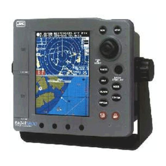
- Page 1 INSTRUCTION MANUAL MENU N 42 31.000'COG122.3 T DGPS W 81 49.000'SOG 25.5KTS PUSH OPEN PUSH SELECT RANGE C-MAP CARD PUSH EVENT/ENT MODE EBL/VRM PUSH CENTER OPEN BRT/CLR STBY PC I/F PORT 1 800 RADAR COLOR LCD RADAR-PLOTTER 1 800 RADAR Color Radar / Plotter...
-
Page 2: Before You Begin
Color Radar/Plotter Before You Begin Thank you for purchasing our RADAR 1800 Color LCD Radar/Plotter. This unit is a sophisticated and easy to use integrated color radar and color plotter. When the unit is connected to a GPS or Loran... -
Page 3: Symbols Used In This Manual
Symbols Used In This Manual Related Symbol Marks In this manual, and on the equipment, we use several warning signs to call your attention to important items that, if not handled correctly, could present danger to yourself or property. These warning note classifications are as described below. -
Page 4: Usage Hints
Usage Hints WARNING Do not remove the cover of the Operate the unit only unit. Doing so may cause an on 12 VDC. electric shock Not doing so may by high voltage cause fire or from within electrical shock. the product’s enclosure. - Page 5 CAUTION Be sure to connect a cable to the When disconnecting grounding terminal when installing. the power cable, Not doing so may cause an electric be sure to grasp shock or it by the plug. Never pull on the excessive connecting cord noise from/ itself, as doing so...
-
Page 6: Emc Installation & Service Guidelines
In general this will not damage the equipment but it can lead to it resetting, or momentarily may result in faulty operation. This can then be avoided by turning off the RADAR 1800 prior to starting the boat engines for instance. - Page 7 • Some products generate high voltages, and so never handle the cables/connec- tors when power is being supplied to the equipment. • Always report any EMC related problem to your nearest JRC dealer. We will use any such information to improve our quality standards.
-
Page 8: Outside View
Outside View Scanner Unit Display Unit GPS/DGPS Sensor (Option) GPS-112/GPS-112W DGPS212/GPS-212W... -
Page 9: Table Of Contents
Contents Before you begin ................1 Symbols used in This Manual ............2 Usage Hints ..................3 EMC Installation & Service Guidelines ........... 5 Outside View ..................7 Definition on Terms................. 16 SECTION 1 Introduction ........19 Function ..................19 Features ..................20 Components ..................21 Standard Equipment.............. - Page 10 TUNE PRESET ..............38 Relative BEARING alignment ..........39 DISPLAY TIMING ..............39 STC PRESET ................. 39 Connecting Personal Computer ............40 Inserting a Chart Card ..............41 Removing a Chart Card ..............41 SECTION 3 Operation ........... 42 Screen Layout ................42 Control Panel ................45 Rear Panel ..................47 Basic Operations ................48 The Power Control (Turning the Radar ON and OFF) ....
- Page 11 INTERFERENCE REJECTION ..........62 Setting AUTO/MANUAL SEA Clutter Rejection ......63 Setting AUTO/MANUAL TUNING........... 63 Target EXPANDER ..............63 PROCESS ..................64 TRAILS..................64 CLEAR TRAILS ................65 WAYPOINT ................65 Setting Radar COLOR ..............65 PLANNED-TX MODE .............. 66 Setting GUARD ZONE ...............
- Page 12 OBJECT INFO (Displaying detailed information of a specified point) ..79 EDIT ................... 80 Editing a waypoint ..............80 EDIT IN CHART ....................80 Storing a waypoint .................... 80 Modifying a waypoint ..................81 Erasing a waypoint .................... 81 Moving waypoint ....................81 Go to a waypoint ....................
- Page 13 COLOR ........................89 TX-PLAN ....................... 90 PLOT SETTING ..............90 TRACK ERASE (Erasing a track) ................90 MARK ERASE (Erasing a mark) ................90 MARK SIZE (Selecting a size) ................. 90 TRACK SETUP ..................... 90 TRACK PLOT (Selecting memory intervals) ............ 90 MEMORY SIZE (Selecting a number of points) ..........
- Page 14 SPEED SCALE (Setting a display range of the speed graph) ........93 GPS SETTING ..............94 VESSEL POSITION (Setting the vessel position) ........... 94 TIME DIFFERENCE (Setting the time difference) ..........94 ANTENNA HEIGHT (Setting the antenna height) ..........94 GEODETIC DATUM (Setting a geodetic system) ..........
- Page 15 CUSTOM SETUP ............... 102 PRESET ........................ 102 CUSTOM INITIALIZE ..................102 MEMORY COPY ..............102 USE THE CARD ....................103 USE THE PC ....................... 104 ALARM ................105 NAV ALARM (Navigation alarms) ................ 105 RADAR ALARM ....................107 BZ ALARM ......................107 TEMP.
- Page 16 Operation ..................128 The following is for the jumpers in the junction box. (setting 1) ... 128 The following is for the jumpers in the junction box. (setting 2) ... 128 SECTION 7 After-Sales Service ......130 When Asking for Service .............130 Checks and Inspection ..............130 SECTION 8 Disposal ..........
-
Page 17: Definition On Terms
Definition on Terms 2D(two- dimensional)..Position fixing using satellites and height information. 3D(three-dimensional) ..Position fixing using satellite information only from four or more satellites. Anchor alarm ....An alarm indicating that the vessel has deviated more than the set distance from a waypoint. Arrival alarm .... - Page 18 HDOP ......Indicates the accuracy of Horizontal position fixing. The smaller the number shows the more accurate the position fixing. When the satellites are grouped together, HDOP increases and position fixing accuracy is poorer. When the satellites are Farther apart, HDOP decreases and position fixing accuracy is enhanced.
- Page 19 Relative bearing ....The direction of a target from own ship expressed as an angular displacement from own ship’s heading. Relative course ....The direction of motion of a target relative to own ship’s position expressed as an angular displacement from north.
-
Page 20: Section 1 Introduction
Whether you purchased this radar because of its compactness, power economy, ease of installation, or long term reliability, one thing is certain;the moment you turn on your RADAR 1800 Display you will know that you are seeing a revolutionary new concept in Radar technology. -
Page 21: Features
Features Easy To Operate Features Like the JRC RADAR 1000 and RADAR 1500, the JoyStick and Jog Dial are mounted to provide easy to operate for everyone. Scan Correlation Feature The Scan Correlation signal processing function, normally only available in... -
Page 22: Components
Components When unpacking your RADAR 1800, you should find the following standard equipment in the carton. If any items are missing, please notify your JRC dealer immediately. Standard Equipment No Description Model No. Qty. Remarks Display Unit NCD-4300 Scanner Unit... -
Page 23: Construction
Construction 115 (4.5) 27 (1.1) 253 (10) 210 (8.3) Unit : mm (inch) Figure 1-2... - Page 24 450 ( 17.7) 200 (7.9) 260 (10.2) (3.6) 15 (0.6) 141.4 (5.6) Unit : mm (inch) Figure 1-3...
-
Page 25: System Configuration
System Configuration SCANNER UNIT SHIP’S MAINS Figure 1-4... -
Page 26: Section 2 Installation
Leaving the equipment in this condition may cause electric shock or malfunction. The two most important considerations for mounting the RADAR 1800 Color Radar/Plotter display unit are: • Choosing the best location for operating and viewing •... - Page 27 Figure 2-1 To mount the unit, remove the mounting yoke from the unit by loosening the yoke knobs on each side of the RADAR 1800. Attach the bracket to the desired mounting surface with the setting screws ( 5×25mmSUS, 4Qty.) included in the kit, refering to Figure 2-1.
-
Page 28: Console Mounting/ Surface Mounting
Console Mounting/ Surface Mounting ATTENTION Make sure there are no hidden electrical wires or other items behind the desired location before proceeding. Also check that you have free access for mounting and cabling. 1) Select a mounting location: a clear, flat area of at least 8”(203mm) wide by 8” high, having 5.5”(140mm) depth behind the panel. -
Page 29: Installing The Scanner Unit
Installing the Scanner Unit Connecting the Scanner Unit Cable Connect the scanner unit cable as follows. CAUTION Be careful not to injure your finger or hand by the waterproof cap mounting groove when installing the Display connector. 8-CORES COMPOSITE CABLE 10 m : CFQ6531-10 15 m : CFQ6531-15 20 m : CFQ6531-20... -
Page 30: Installing The Gps/Dgps Sensor
Installing the GPS/DGPS Sensor Selecting the Position for Installation CAUTION When connecting the cable attached to the equipment, do not bend to an acute angle, twist, or impart excessive force. Doing so may damage the cable and cause a fire or an electric shock. Do not install the equipment in a place with excessive vibration. - Page 31 NCD-4300 DISPLAY UNIT CFQ-6532 (2m) T.RED TO SHIP'S MAIN SHIP'S +12V MAIN+ TO GPS/MAGNETIC COMPASS T.BLK SHIP'S MAIN- COMPASS DATA IN- DATA IN+ COMPASS DATA IN+ DATA IN- DATA OUT NKE-1065 SCANNER UNIT T.RED NMEA T.BLU DATA OUT+ T.RED NMEA T.ORN DATA IN- T.BLU...
-
Page 32: Installation Procedure
Installation Procedure Installation CAUTION Insluate the GPS/DGPS sensor case from ground. Without insulation, a considerable amount of current frow from ground to this equipment. A considerable amount of current may cause equipment damage. The aluminum bottom of the GPS112/DGPS212 are designed so that it can be installed on the navigation antenna mount unit or on an extension mast conforming to 1”... - Page 33 Belt fitting method GPS/DGPS Sensor Do not coil the fitting belt around the aluminum base. 20mm (Sensor case bottom to Mast top) Plastic Cable Mounting Fitting belt Unit Mast (ø26- ø50) 1. Loosen the fitting belt screw 2. Coil the fitting belt around 3.
-
Page 34: Connecting Dc Power
Connecting DC Power WARNING Do not touch the ground terminal and vessel ground on the display unit at the same time without the ground terminal earthed. Otherwise, you may suffer an electric shock. CAUTION RED to the positive. BLACK to the negative. Do not mistake the colors, as doing so will cause a malfunction. -
Page 35: Grounding The Display Unit
(NKE-1065) simply not turn on. Connector to CAUTION GPS/DGPS Sensor Be careful not to injure JRC type GPS112 or your finger or hand by DGPS212 the waterproof cap mounting groove when installing the power cable. 10 amp fuse Connect to... -
Page 36: Connecting Gps/Dgps Sensor Or Making Nmea0183 Data Connections (Option)
When displaying the latitude and longitude of your vessel on the screen, or using the NAVIGATION mode, you are required to connect the optional GPS112 or DGPS212 sensor to the RADAR 1800, or input the data of navigational information in the NMEA0183 format from navigation equipment. - Page 37 (2) locking posts on the connector body. This is a tight connection. For leverage it may be helpful to first insert and lock the connector into its mating plug on the RADAR 1800 back panel. GROMMET...
-
Page 38: Connecting Electronic Compass/Gps Compass (Option)
Connecting Electronic Compass/ GPS Compass (Option) By connecting the NMEA-183 formatted output (HDM) or the optional GPS Compass (JLR-10), the realtime and precise course information is input and you can use more precise North-Up or Course-Up mode. Connection RED: Ship’s main BLK: Ship’s main YEL: Compass Data GRN: Compass Data... -
Page 39: Operating The Installation Menu
Operating the INSTALLATION menu To access this menu: INSTALLATION SIMULATION Press key to display the MAIN menu. MENU MENU INITIAL POS. N 0°00.000’ Select INSTALLATION> by up/down, push . The Joystick Joystick E 0°00.000’ CLOCK ADJUST 00/00/0000 INSTALLATION menu is displayed. 00:00 DATE &... -
Page 40: Relative Bearing Alignment
Note: There may be 2 positions where the targets are strong. Select the one that has the larger value of “TUNE PRESET”. • Push the to save and exit. Joystick Relative BEARING alignment This adjustment should be performed after installation or a master BEARING reset to avoid incorrect bearing readouts and picture orientation. -
Page 41: Connecting Personal Computer
Connecting Personal Computer Connect the RADAR 1800 to a personal computer as follows in order to transfer data between them. Cable connection Personal computer RADAR 1800 CD (1) NC (1) RD (2) RD (2) TD (3) TD (3) DTR (4) -
Page 42: Inserting A Chart Card
Inserting a Chart Card q Check that the card is C-MAP NT C-Card with the required chart stored on w Open the card cover, at the higher left of the display front panel. e Hold the card with the title label towards the left and upside down, as shown in the illustration. -
Page 43: Section 3 Operation
Operation SECTION 3 Screen Layout SHIP POSITION COURSE & SPEED BEARING MODE OWN SHIP ICON GPS STATUS EBL & VRM JOG-DIAL N 35° 41.054'COG185.7° RANGE SCALE & FUNCTION W139° 34.472'SOG 0.0KTS RANGE RING 2 5 . 0 1 . 2 1 LEVEL INTERVAL S : SEA... - Page 44 No. ITEMS Displaying symbols q OWN SHIP ICON Selected own ship ICON. w SHIP POSITION Ship position is available when used with GPS/ DGPS sensors or NMEA0183 format data is received. e COURSE & SPEED COG (the ship’s course over the ground) and SOG (the ship’s speed over the ground) appears.
- Page 45 SHIP POSITION COURSE & SPEED GPS STATUS N 4 2° 3 4 . 2 55 ' C O G1 2 2 .3° D G P S W1 2 2° 1 9 . 4 87 ' S O G 2 5 .5 K T S N 4 3°...
-
Page 46: Control Panel
Control Panel Figure 3-3 shows the panel keys and their functions. MENU PUSH OPEN PUSH SELECT RANGE C-MAP CARD PUSH EVENT/ENT MODE EBL/VRM PUSH CENTER OPEN BRT/CLR STBY PC I/F PORT 1 800 RADAR COLOR LCD RADAR-PLOTTER Figure 3-3 Control Panel No. - Page 47 No. Keys Functions r RANGE Sets range scale by SOFT Key. t JOY-STICK Position cursor setting. Up/Down/Right/Left: Selects and changes an item when each menu is displayed. Push: Fixes the set value when each menu is displayed. Enters a marker when no menu is displayed. Registers EVENT in the NAVIGATION mode.
-
Page 48: Rear Panel
Connects GROUND. y NMEA connector Connects NMEA0183 format data u GPS connector Connect GPS/DGPS SENSOR * Connectable JRC’s GPS/DGPS sensor only. (Refer to p.35) i SCANNER connector Connects the scanner. o DC12V / COMPASS connector Connects power supply and magnetic/GPS compass. -
Page 49: Basic Operations
Basic Operations When you turn the power of the RADAR 1800 on, the initial screen appears. RADAR 1800 COLOR RADAR/PLOTTER N O T I C E T H I S D E V I C E O N L Y... -
Page 50: The Power Control (Turning The Radar On And Off)
The Power Control (Turning the Radar ON and OFF) • Push once to turn the power on. STBY/OFF STBY/OFF • Push to transmit. TX/OFF TX/OFF • Push to enter the stand-by mode. STBY/OFF STBY/OFF • Push simultaneously to turn the power off. STBY/OFF STBY/OFF TX/OFF... - Page 51 Press Soft Key, there may appear the following Soft Keys. Changes the screen to the full chart screen. C H A R T F U L L Changes the screen to the full Radar screen. R A D A R F U L L Changes the screen to the DGPS status screen.
- Page 52 CHART Mode Select CHART to display the chart on the full screen. N 42 ° 34.255'COG 92.5 ° DGPS W122 ° 19.487'SOG 25.5KTS Course Deviation Indicator (CDI)/COMPASS Mode Select CDI/COMPASS to display the navigation full screen display. The N 4 2 ° 3 4 . 2 5 5 ' C O G 9 2 . 5 ° D G P S W 1 2 2 °...
- Page 53 [Numeric Data] DPT : Depth SOG : Speed (Over Ground) (unit: KTS=knots, KPH=km/hour, MPH=mile/hour) WPT: Waypoint ID COG:Vessel course over ground (unit: degree/ T=true, M=magnetic) BRG : Bearing to destination (unit: degree/ T=true, M=magnetic) RNG: Distance to destination (unit:0.1 NM) XTE : Cross track error.
-
Page 54: Vessel's Information/Waypoint's Information
WIND DATA Mode To display the wind display with numerical data, it is necessary to N 4 2 ° 3 4 . 2 5 5 ' C O G 9 2 . 5 ° D G P S W 1 2 2 ° 1 9 . 4 8 7 ' S O G 2 5 . 5 K T S °... -
Page 55: Graph Display
Information about the position, direction, and distance W P T I N F O 1 of a waypoint and the GPS/DGPS status is displayed. N 4 2 ° 34.255' BRG122.3 ° TDGPS W1 22 ° 19.487' RNG 5.5NM Information about the name, and distance of a waypoint, W P T I N F O 2 the estimated time of arrival, and the GPS/DGPS status... -
Page 56: Using The Jog Dial
Using the Jog Dial • Push and turn: Select function and adjust level. Push: Select SEA, RAIN, GAIN, TUNE controls repeatedly. In AUTO mode, skip control. Selected control is displayed highlighted. Turn: SEA: reduces sea clutter. No bar in Auto mode. -
Page 57: Buzzer On/Off
OK and push it in to Joystick excute the MASTER reset. After the MASTER reset is executed, the MASTER RESET SELECT RESETTING TYPE. RADAR 1800 is rebooted automatically. To abort the MASTER reset, select CANCEL and push the Joystick SOFT HARD (Refer to “Master Reset and Language Select Operation”... -
Page 58: Radar Operation
Radar Operation All radar functions operates only in the RADAR full screen or in the RADAR/CHART screen. If any other screen mode is selected the radar will be put into standby mode. Selecting a RANGE [RADAR full screen mode] • Press to display two Soft Keys. -
Page 59: Adjusting Receiver Sensitivity
When the radar has warmed up, it may be necessary to make a further fine tune adjustment. AUTO TUNE The RADAR 1800 has an automatic tuning feature. In this mode, the radar automatically tunes itself for best efficiency at all ranges. (Refer to p.63) -
Page 60: Adjusting Rain Clutter
Adjusting RAIN CLUTTER • Press the until RAIN is highlighted in the upper right Jog Dial corner of the display. Rotate the clockwise or Jog Dial counterclockwise, to vary the level and thus control the strength of echoes returned from rain or snow. An on-screen bar indicates the rain level selected. -
Page 61: Bearing Measurement
Bearing Measurement q Using the bearing scale Using the bearing scale on the screen, visually estimate a line from the center of the display(ship’s position) projected through the center of the target, to reach the bearing scale around the perimeter of the display. -
Page 62: Radar Operating Menu
RADAR Operating Menu • Press , select the “RADAR SETTING>” and push the RADAR SETTING MENU MENU RINGS , the “RADAR SETTING” menu is displayed. Joystick BEARING INTERFERENCE MANUAL TUNE AUTO EXPANDER PROCESS TRAILS CLEAR TRAILS TX-PLAN > WAYPOINT COLOR >... -
Page 63: Interference Rejection
[CUP RESET] After a course change, you can select CUP RESET so that the Heading line is up at the head of the display. • Select the “BEARING” in RADAR SETTING menu and push the , the “BEARING” pull-down menu is displayed. Select Joystick HUP/NUP/CUP/ CUP RESET by up or down and push... -
Page 64: Setting Auto/Manual Sea Clutter Rejection
Setting AUTO/MANUAL SEA Clutter Rejection The RADAR 1800 has an automatic sea clutter control feature. In this mode, the radar automatically suppress the effect of sea clutter. ATTENTION The AUTO SEA is used to simply suppress sea clutter returns. So no target in the sea clutter can appear on the display clearly. -
Page 65: Process
• Select the “EXPANDER” in RADAR SETTING menu and push the EXPANDER , the “EXPANDER” pull-down menu is displayed. Change Joystick settings to ON/OFF by right or left and push Joystick Joystick PROCESS This feature allows the operator to detect a weak signal target or to PROCESS detect a target in the sea clutter. -
Page 66: Clear Trails
CLEAR TRAILS The trails are drawn for anything that move on screen, sometime CLEAR TRAILS the screen will be filled by trails. You can clear the screen. • Select the “CLEAR TRAILS” in RADAR SETTING menu and push , the “CLEAR TRAILS” pull-down menu is displayed. Joystick Change settings to NO/YES by right or left and push... -
Page 67: Planned-Tx Mode
[To change a echo color] • Select the “ECHO” in COLOR menu and push the , the Joystick ECHO “ECHO” pull-down menu is displayed. Change settings by Joystick YELLOW right or left and push Joystick GREEN In this menu, you can select a echo color in yellow, green, orange, or ORANGE color. -
Page 68: Setting Guard Zone
Setting GUARD ZONE The Guard Zone may be a zone completely surrounding the vessel or a partial trapezoidal zone to monitor targets entering or departing the specified area. Targets entering or leaving the guard zone will sound audible and visible alerts to the operator. In the “IN” alarm mode, an alarm will sound if a target enter the area. - Page 69 [Setting alarm sensitivity] • Select the “ALARM LEVEL” in RADAR ALARM menu and push the ALARM LEVEL , the “ALARM LEVEL” pull-down menu is displayed. Joystick Change settings by right or left and push Joystick Joystick The smaller value of “ALARM LEVEL” is higher sensitivity. For example a setting of 2 would activate the alarm for a small target while for the same target a setting of 7 might not activate it.
-
Page 70: Display Of Radar Transponder
• Next, move the cursor to the desired end point of your guard zone then press the Joystick A ring in the distance range is displayed by the solid line at this time. Point Start Point END POINT Display of RADAR Transponder SART (Search and Rescue Radar Transponder) is life preserving device approved by GMDSS which is used for locating survivors in the event of a disaster or distress. - Page 71 ATTENTION When above settings q to t are made to display SART signals, objects around the own ship will not appear on the radar screen, so perform thorough visual monitoring of the sea area around the own ship to avoid any collision or stranding.
-
Page 72: Plotter Operation
Plotter Operation Using The Joy Stick in CHART mode Enter the Event You can enter the EVENT symbol at the own ship’s position. • Confirm the shape of cursor mark as “ ”. (Don’t move the cursor EVENT IN mark) •... -
Page 73: Soft Keys At The Waypoint Mode
Modify / Erase / Move / Goto a waypoint • You can edit a stored waypoint same as EDIT IN CHART function. (Refer to p.81) Soft Keys at the WAYPOINT Mode By selecting WAYPOINT in the above menu you can display the following four soft keys by pressing on the joystick. -
Page 74: Man Overboard
Man Overboard • Press the key to place the marker at the own ship’s position. MAN OVERBOARD! • Press the to the left or right to select YES or NO and push it Joystick BEGIN NAVIGATION to complete the selection. TO THE MAN Notes: OVERBOARD POINT. -
Page 75: In The Radar/Chart Display
In the RADAR/CHART display [RADAR/CHART screen mode] • Press to display four Soft Keys. RANGE RANGE ZOOM ZOOM RANGE RANGE Magnify the chart. Z O O M Reduce the chart. Z O O M O U T Decrease the range scale. The minimum range scale is R A N G E 0.125NM. -
Page 76: Planned Route (Navigating According To A Planned Route)
PLANNED ROUTE (Navigating according to a planned route) • Select PLANNED ROUTE to display the ROUTE LIST screen and N E W A L L two Soft Keys R O U T E E R A S E • Select a route and press the to start the navigation by the Joystick selected route. - Page 77 S T A R T • Press the Soft Key to display the START NAVIGATION N A V popup menu, after confirmation the specified waypoints are connected to each other by lines to begin the navigation. TEMPORARY ROUTE Start point Relay points End point P O I N T...
-
Page 78: Nearest Port (Searching For And Navigating To A Nearest Port)
NEAREST PORT (Searching for and navigating to a nearest port) • Select NEAREST PORT to display the full chart and four Soft Keys NEAREST PORT V E S S E L C U R S O R Z O O M Z O O M , and O U T... -
Page 79: Wpt Step (Selecting The Method To Switch The Waypoint)
(Selecting the method to switch the STEP waypoint) W P T Press the Soft Key to display the WPT STEP WPT STEP S T E P popup menu to select the method to update a waypoint AUTO MANUAL between AUTO (automatically) and MANUAL (manually). -
Page 80: Tidal Info
TIDAL INFO (Displaying tide height graph of a speci- fied point) This feature can display the Tide Height Graph of a specified point N 42° 34.255'COG122.3° DGPS W122° 19.487'SOG 25.5KTS based on the tidal information stored in the chart card. The change of sea level can be forecast with the help of this feature. -
Page 81: Edit
EDIT • Press , select EDIT> , and press to display the four MENU MENU Joystick W A Y R O U T E T R A C K C O N S T - Soft Keys: , and P O I N T P L A N C O N V . -
Page 82: Modifying A Waypoint
Modifying a waypoint • Select a stored waypoint you want to modify. Press the Joystick WPT.NO.001 move the cursor to select an icon of the waypoint and push it in to complete the selection. MODIFY ERASE MOVE GOTO • Press the up or down to select MODIFY and push it in to Joystick MODIFY WAYPOINT... -
Page 83: Edit By List
EDIT BY LIST EDIT WAYPOINT • When you select EDIT BY LIST, the waypoint list and two Soft Keys 1 / 100 N E W J U M P appear. E 35 ° 45.123' CAMBRIA W P T W120 ° 54.105' OUR FIRST PORT E 35 °... -
Page 84: Copying A Waypoint
Copying a waypoint COPY WAYPOINT • Select a waypoint number you want to copy. • Press the up or down, or press the to the left or Joystick Jog Dial right to select a number to which you want to copy the waypoint. N 42 °... -
Page 85: Editing A Route
Editing a route • Select a route you want to edit from the EDIT ROUTE PLAN list ROUTE:HIGHWAY 1 / 4 and press the to display the window of the selected route. Joystick E 3 5 ° 4 5 . 1 2 3 ' 0 0 0 CAMBRIA W 1 2 0 °... -
Page 86: Converting A Track To A Planned Route
T R A C K (Converting a track to a planned C O N V . route) • You can convert an arbitrary part of a track into a route plan. TRACK • Press the Soft Key to display the TRACK- CONV. -
Page 87: Divide
Notes: • The same names as the waypoint is automatically set and no comment is MEMORY FULL! entered. CANNOT REGISTER • If memory is not enough, the following message appears. THE ROUTE. • Press any key or wait about seven seconds to delete the message. ERASE ANY REGISTRY. -
Page 88: Constructing A Rectangle
Constructing a rectangle • You can construct a rectangle in the chart. • You can use the rectangle you have constructed as the Alarm Area by specifying it in the ZONE (Danger Zone Alarm). (Refer to p.101) R E C T . •... -
Page 89: Menu Operations
Menu Operations General Following the basic operations described below, you can easily perform all menu operations using only the Joystick Selecting an item: • Press the up or down to select an item and push it to Joystick complete the selection. When you select a normal item, the pull-down menu of the selected item opens. -
Page 90: Bearing
BEARING You can select a bearing mode among three bearing mode. (Refer to “DISPLAY MODE” p.61) INTERFERENCE REJECTION The Interference Rejection (IR) can be turned to on or off via this menu. (Refer to “INTERFERENCE REJECTION” p.62) The automatic sea clutter suppress mode can be turned to on or off via this menu. -
Page 91: Tx-Plan
TX-PLAN In this menu, you can program transmitting time and STBY time. (Refer to “PLANNED-TX MODE” p.66) PLOT SETTING TRACK ERASE (Erasing a track) • In this menu, you can delete the currently displayed tracks by each PLOT SETTING color or all. TRACK ERASE MARK ERASE MARK SIZE... -
Page 92: L/L-Td Convert
L/L - TD CONVERT • In this menu, you can display the position in L/L (Latitude/ L L-TD CONVERT Longitude) or TD (Time Difference), select a setting for Loran-C, and POSITION DISP LAT/LON LORAN-C CHAIN GRI 4990 perform TD correction. TD1 0 TD2 0 POSTION DISPLAY (Selecting a format of position display) -
Page 93: Chart Colors
CHART COLORS • In this menu, you can select a color for LAND, SEA and L/L GRID. LAND (Selecting a color for the land) • In this menu, you can select a color for the land. SEA (Selecting a color for the sea) •... -
Page 94: Depth Contour
DEPTH CONTOUR • In this menu, you can enable visualization of depth contour and setting range. DETAILED • In this menu, you can select the detaile about chart presentation. Normal : normal detaile high : high detaile GRAPH SETTING • In this menu, you can set the scale of the water depth, temperature, GRAPH SETTING and speed graphs. -
Page 95: Gps Setting
GPS SETTING • In this item, you can perform the initial settings when JRC’s GPS/ GPS SETTING DGPS sensor GPS112 or DGPS212 is connected to the RADAR POSITION N 0° 00.000' E 0° 00.000' 1800. The menu includes both basic settings and initial settings. The + 00:00 TIME DIFF. -
Page 96: Hdop Level (Setting The Hdop Level)
HDOP LEVEL (Setting the HDOP level) • In this menu, you can set the upper limit of the HDOP level using this item. The HDOP level indicates the geodetic precision determined by the constellation of the GPS satellites. Precision is increased as this level decreases and vice versa. -
Page 97: Waas Setting
WAAS SETTING • In this menu, youcan perform the basic settings of the WAAS module WAAS SETTING of the DGPS sensor. MODE AUTO RANGING NG WAAS NO USE Note: WAAS NO. AUTO TX COMMAND • Use TX COMMAND to send the values in the following setting. MODE: AUTO/MANUAL •... -
Page 98: Installation
OPERATION > vessel position, vessel speed, course using the dummy data stored initially in the RADAR 1800. While the simulator is activated, you can simulate almost all operations except the operation of the INSTALLATION menu and radar control. INITIAL POSITION (Setting the standard position of the chart display) •... -
Page 99: Data In/Out
Refer to “TUNE PRESET” p.38. [STC PRESET] Refer to “STC PRESET” p.39. DATA IN/OUT • In this menu, you can set the RADAR 1800 so that you can get the DATA IN OUT TEMP. IN NMEA data such as water temperature or vessel’s speed, or issue the data in... -
Page 100: Depth In (Selecting Depth Data Input)
NMEA0183 sentences of $xxDPT or $xxDBT are output from the connected water depth gauge. (You can check this easily using the self test mode of the RADAR 1800.) COURSE IN (Selecting course data input) • In this menu, you can select the vessel’s course data input from GPS, GPS compass, or magnetic compass. -
Page 101: Nmea Out (Putting Out Data)
NMEA0183 sentences of $xxGGA or $xxRMC are output from the connected external navigation aids. (You can check this easily using the self test mode of the RADAR 1800.) NMEA OUT (Putting out data) • In this menu, you can issue the data in the specified format. -
Page 102: Magnetic Corr. (Correcting The Magnetic Compass)
NAVIGATION mode. The value of the LOG is maintained after the RADAR 1800 is turned OFF. OPERATION • This menu is used to set the Joystick mode, the CENTER soft key... -
Page 103: Custom Setup
C-MAP User C-Card, USE THE CARD > USE THE PC > or transfer the data to the RADAR 1800. You can also transfer the data to a personal computer. • This menu includes two submenus USE THE CARD and USE THE... -
Page 104: Use The Card
• If the message “NO CARD!” appears even if the C-MAP User C-Card is inserted correctly, the data stored in the card may not be compatible with the RADAR 1800 or the card is not initialized. Execute CARD FORMAT before use. -
Page 105: Use The Pc
• To use this function, it is necessary to install the communication tool exclusive for the PC. This communication tool is not attached to the RADAR 1800. Please download it from our Internet site. (URL is found on the backside of the manual). This communication tool is free. -
Page 106: Alarm
Note: • If invalid data are received, the message “ERROR!” appears. In this case, check again whether the data are broken. ATTENTION While receiving data, the transmission and reception to/from GPS and that of the NMEA data are terminated. ALARM ALARM SETTING •... - Page 107 OFF-COURSE (Off Course Alarm) • When turned on, this alarm shows a message on the screen and also sounds the buzzer when the deviation from the intended course becomes equal to or greater than the operator’s preset value. ZONE (Danger Zone Alarm) •...
-
Page 108: Radar Alarm
RADAR ALARM There are three kind of radar alarms, guard zone alarm, scanner rotation stop alarm, and communication line alarm for external heading sensor. Guard Zone IN/OUT alarm. Scanner rotation stop alarm. (No Bearing Zero signal alarm) Communication line alarm. (No signal input from heading sensor) [Setting Guard Zone] •... -
Page 109: Temp. Alarm (Temperature Alarms)
TEMP. ALARM (Temperature alarms) • Select “TEMP. ALARM>”, and press , the “TEMP. TEMP. ALARM Joystick TEMP UPPER OFF 60.0 ALARM” menu is displayed. OFF 50.0 TEMP LOWER OFF 6.0 TEMP RATE TEMP UPPER (Temperature Upper Limit Alarm) • When turned on, this alarm shows a message on the screen and also sounds the buzzer when the temperature value sensed is greater than the operator’s preset upper temperature value. -
Page 110: Self Test Operation
Self Test Operation • The RADAR 1800 has a built-in self test function with which you SELF TEST Rx.xx MENU can check the operating status of the RADAR 1800 automatically. SRAM Lxxx Rxxx DRAM RANGE RD ROM Rx.xx Also a function of monitoring input NMEA0183 formatted sentences... -
Page 111: Master Reset And Language Select Operation
To abort the MASTER RESET and language select, select CANCEL and push the Joystick Note: • When a backup error occurs, the RADAR 1800 enters the MASTER MASTER RESET RESET mode automatically, and language select menu opens. In this case, EBL BEARING you cannot abort the MASTER RESET. - Page 112 Master Reset Condition Item English, Italian Other language MENU RADAR SETTING RINGS BEARING INTERFERENCE REJECTION MANUAL TUNE AUTO EXPANDER PROCESS TRAILS TX-PLAN TX-PLAN TX PERIOD 10 SCAN STBY PERIOD 3 MIN WAYPOINT COLOR INSIDE BLUE OUTSIDE ECHO YELLOW TRAILS PLOT SETTING MARK SIZE SMALL TRACK SETUP TRACK PLOT TIME 1...
- Page 113 CUSTOM CHART CHART BOUNDARY LIGHT SECTORS ON, C BUOY & BEACON INTNL. LAND MARKS NAMES RIVER & LAKE CULTURAL BOTTOM TYPE UNDER WATER SOUNDING DEPTH UPPER 0FT LOWER 100FT DEPTH SHADING UPPER 30FT LOWER 1000FT DEPTH CONTOUR UPPER 0FT LOWER 3000FT DETAILED NORMAL GRAPH SETTING GRAPH DISPLAY...
- Page 114 INSTALLATION SIMULATION INITIAL POS. Preserved (Customer’s setting) CLOCK ADJUST Preserved (Customer’s setting) DATE & TIME 12 HOUR RADAR ADJUST EBL BEARING RELATIVE PRF SHIFT BEARING DISPLAY TIMING TUNE PRESET STC PRESET DATA IN/OUT TEMP. IN NMEA DEPTH IN NMEA COURSE IN POSITION IN NMEA OUT See NMEA Setting List...
- Page 115 EDIT WAYPOINT EDIT IN CHART ROUTE PLAN STICK CURSOR CENTER SELECT ROUTE WAYPOINT DIRECT PLANNED ROUTE SEQUENCE STEP AUTO STOP WATCH 00:00:00.00 EBL/VRM MODE RADAR CENTER CENTER BRT/CLR BRIGHT CONTRAST...
-
Page 116: Section 4 Maintenance
Scanner Unit When inspecting the scanner unit of the RADAR 1800, be sure to turn off power to the display unit. Keep watches or magnetic cards away from the modulator block as it... -
Page 117: Radome Scanner Unit
Radome Scanner Unit q Radome A radome surface contaminated by smoke, dust, or paint would cause attenuation or reflections of radio waves, resulting in reduced radar performance. Periodically check the radome scanner unit. If it proves dirty, wipe the radome surface with a soft lint-free cloth moistened with alcohol or damped cloth. -
Page 118: Section 5 Principle
Principle SECTION 5 Radar Basics The role of radar operator is to analyze the echos on the screen to assist in proper navigation and safety of the vessel. To do the best job it is imperative to understand the operation including advantages and weaknesses of radar. The best way to learn is in good visibility conditions so proper comparisons can be made between visual sightings and the representations presented on the radar display. -
Page 119: False Echoes
False Echoes Shadows Owing to the location of a scanner, surrounding masts and structures may block the propagation of radar waves in those directions. This can be noticed by thin or weak shadow sectors in the nearby sea clutter returns. Since these shadows are fixed due to the physical surroundings on the vessel, it is necessary for the operator to be aware of them and realize that targets in those sectors may be weaker or blanked out. - Page 120 False Echo by Multiple Reflection As Figure 5-4, when the own ship is in side by side with a large ship or building, evenly spaced plural echoes appear in one direction. In this case, echo is the nearest echo to the own ship. Figure 5-4 Radar Interference When other ship’s radar operated in same frequency is the vicinity of own...
-
Page 121: Gps/Dgps Basics
GPS/DGPS Basics The Navstar/GPS system is a satellite-based radio navigation system designed to provide global, continuous 24 hour-per-day, all weather, accurate position data for navigators. The GPS(Global Positioning System) is based on a GPS sensor’s ability to accurately measure the propagation time of signals transmitted from orbiting satellites in your sensor. -
Page 122: Differential Gps (Dgps)
Differential GPS (DGPS) The differential GPS comprises a reference station with its position(latitude and longitude) accurately known, a beacon station for radio broadcasting of DGPS correction data, and user-owned GPS sensor equipped with a differential correcting function. The GPS sensor is used to fix the position of the reference station whose position is accurately known and to compare this with the actual reference station position to get range errors. -
Page 123: Wide Area Augmentation System (Waas)
GPS112W may be not available for use during the test transmission period due to system upgrades carried out to improve performance. JRC is not liable for any loss while using the WAAS satellites during test transmissions, or any malfunction of the GPS112W by the upgrades of WAAS system. -
Page 124: Section 6 Interswitch (Option)
Interswitch (option) SECTION 6 Outline Interswitch is a device used to switch the antenna between two display units. The configuration is as shown on the attachment: Set the standard display unit and antenna to plus; this is then the junction box and two Interswitch cables and specified sub-unit. -
Page 125: Construction
Construction NKE-1065 RECEIVER SCANNER CFQ-6531 (10m) NCZ-1432 JUNCTION BOX (CABIN) CFQ-6550 (10m) CFQ-6550 (10m) NCD-4300 NCD-4300 1'st DISPLAY 2'nd DISPLAY (CABIN) (UPPER BRIDGE) GPS DATA IN NMEA DATA DC12V DC12V DC12V (ship's main) Figure 6-1 Interswitch system diagram (NQE-1200) -
Page 126: Installation
Installation Setting Jumpers Table 1 is a summary of the operation of the display unit when the jumpers in the switchbox have been set. The mode for setting 1 or 2 can be selected depending on the jumper settings in the Interswitch box. The factory default setting is 2 (settings 3 and 4 are prohibited). -
Page 127: Unit Connecting Cable
Unit Connecting Cable Be sure that the positive and negative polarity for the power connected to both display units is the same. It is necessary to connect the 12 V connector and GND connector to the same terminal. The voltage is 12 V. Also, the switchbox is not sealed against leaks, be sure to install it indoors where it will not be splashed with seawater or liquids. - Page 128 CAUTION Be sure to do connections to the same battery terminal even if it is a 12 volt boat. Particularly, when doing an in-line connection to a 12 volt battery on a 24 volt boat, be sure to connect both display units to only one battery. Connecting both display unit 1 and 2 to separate batteries by cause a serious accident.
-
Page 129: Operation
Operation The following is for the jumpers in the junction box. (Setting 1) TB1 = 1 - 2, TB2 1 - 2 Display unit 1 and display unit 2 can alternately use the antenna each time they are turned ON, whichever display unit is already ON is turned OFF. Example: Turning ON display unit 2 while display unit 1 is ON turns OFF the power to display unit 1. - Page 130 CAUTION While one display unit is transmitting, and another display unit is turned ON, depending on the settings the power may be turned OFF. In cases like this, be sure that transmission status has changed to standby status, then turn ON the power to the other display unit.
-
Page 131: Section 7 After-Sales Service
After-Sales Service SECTION 7 When Asking for Service When you think the RADAR 1800 is not operating normally, consult your dealer, our agent, branch, sales department or subsidiary for advice. Repair during warranty period Should a malfunction occur when the RADAR 1800 has been operated according to descriptions and instructions in the instruction manual, it will be repaired free of charge during the warranty period. -
Page 132: Section 8 Disposal
The RADAR 1800 contains a lithium battery for battery backup. • Dispose of used lithium batteries as non-combustible garbage. • Insulate the + and - terminals by placing a piece of adhesive tape over them before disposal. -
Page 133: Section 9 Specification
Specification SECTION 9 General Type of emission Display type Raster scan, PPI method, vertically long display Display panel 6.5-inch high contrast color LCD Range scale 0.125, 0.25, 0.5, 0.75, 1.5, 3, 6, 12, 24nm Range resolution 25m max. Minimum detective range 25m max. -
Page 134: Scanner
Scanner approx. height 227mm × diameter 450mm Outside dimensions (1.5ft) Mass approx. 5kg Plane of polarization Horizontal polarization Beam width Horizontal beam width 5.2 degrees Vertical beam width 30 degrees Side lobe level -21dB max. Antenna rotation Approx. 32 rpm Transmission output Transmission frequency 9445±30MHz... -
Page 135: Display Unit
Display Unit Mounting Table, Bulkhead, or Flush mount Approx. W253 × H205.5 × D115mm Outside dimension Mass Approx. 2.8kg Display Vertical 6.5-inch color LCD 320 × 234 (1/4VGA) Number of pixels Approx. 133mm × 97mm Display area Display mode RADAR CHART RADAR/CHART horizontal split DATA... -
Page 136: Radar
Radar Color/Graduation Radar video Graduation: 4 Color: 4 (Yellow, Green, Amber, Color (Red/Yellow/Green)) Trail Graduation: 1 Color: 3 (Sky, White, Green) Fix marker, VRM, EBL Color: 1 (Cyan) Letter, dial Color: 1 (White) SHM, Cursor Color: 1 (White) Background color Dark blue/Black Range/Scale spacing Range... - Page 137 Cursor Displays the range, bearing and L/L. Moved using the joy-stick Tuning method Manual/Auto Sea clutter restraint Manual/Auto Rain clutter restraint Manual Radar interference rejection Built-in Bearing scale 5-degree scale, 360 degrees Ship’s heading display Electronic Guard zone alarm “IN” and “OUT” Buzzer sound available.
-
Page 138: Plotter
Plotter Display method Mercator projection (Latitude 70 maximum). Display mode Chart,CDI (Compass), DATA, Wind (Direction/Velocity) Chart data C-MAP card Waypoint Number of waypoint: 1000point Number of Icon: 24 icon Length of waypoint name: 8 characters Display color: 7 colors (work with icon) Route Number of route: 40 route Segment of route:... -
Page 139: Input/Output Signal
VWT, DPT, DBT (V2.0) OUT: APB, BOD, GGA, GLL, RMB, RMC, VTG, XTE, BWC, OSD, RSD (Ver 1.5 or 2.0) Compass input data Electronic compass: NMEA (HDT, HDM, HDG, VHW) (Ver 2.0) GPS Compass: JLR-10 (JRC): NMEA (HDT) PC interface RS-232C... -
Page 140: Appendices
APPENDICES Wiring Diagram 6.5 INCH COLOR LCD A901 H-7WSBS7001A CCFL CABLE DATA CABLE 1 1 1 1 1 1 1 1 1 1 1 1 1 1 1 1 2 2 2 2 2 2 2 2 2 2 2 2 2 2 2 2 3 3 3 3 3 3 3 3... -
Page 141: Geodetic System Table
Geodetic System Table NAME WGS-84 WGS-72 Japan North American 1927 (America) North American 1927 (Canada, Alaska) European 1950 (Europe) Australian geodetic 1966 (Australia) Ordnance Survey of Great Britain (England) NAD-83 No Use No Use Adindan (Ethiopia and Sudan) ARC 1950 (Botswana) Australian Geodetic 1984 (Australia) Bermuda 1957 (Bermuda Islands) Bogota Observatory (Colombia) -
Page 142: Nmea0183 Standard Input/Output Sentences
NMEA0183 Standard Input/Output Sentences Input Sentences NORMAL INPUT $xxGGA Global Positioning System Fix Data $xxGLL Geographic Position-Latitude/Longitude $xxVTG Course Over Ground and Ground Speed $xxRMC Recommended Minimum Specific GPS data $xxHDG Heading, Deviation & Variation $xxHDT Heading-True $xxHDM Heading-Magnetic $xxMTW Water Temperature $xxVHW Water Speed and Heading... -
Page 143: Output Sentences
Output Sentences $INAPB Heading/Track Controller (Autopilot) Sentence “B” Necessary to connect the GPS112 or DGPS212 $IIAPB Heading/Track Controller (Autopilot) Sentence “B” Necessary to connect the GPS112 or DGPS212 $INBOD Bearing-Origin to Destination Necessary to connect the GPS112 or DGPS212 $GPGGA Global Positioning System Fix Data Necessary to connect the GPS112 or DGPS212 $GPGLL... -
Page 144: Waypoint List
Waypoint List Waypoint no. Waypoint name Remarks... - Page 145 Waypoint no. Waypoint name Remarks...
- Page 146 Waypoint no. Waypoint name Remarks...
- Page 147 Waypoint no. Waypoint name Remarks...
- Page 148 FIRST EDITION JUN. 2004. CODE No. 7ZPRD0551B...
Need help?
Do you have a question about the RADAR 1800 and is the answer not in the manual?
Questions and answers