Dell PowerConnect M8024 User Manual
Dell ethernet switch user's guide
Hide thumbs
Also See for PowerConnect M8024:
- Release note (9 pages) ,
- User configuration manual (1294 pages) ,
- Configuration manual (1246 pages)

Related Manuals for Dell PowerConnect M8024


Summary of Contents for Dell PowerConnect M8024
- Page 1 Dell™ PowerConnect™ M6220/M6348/M8024 User’s Guide Model M6220/M6348/M8024 w w w . d e l l . c o m | s u p p o r t . d e l l . c o m...
-
Page 2: Notes, Notices, And Cautions
Reproduction in any manner whatsoever without the written permission of Dell Inc. is strictly forbidden. Trademarks used in this text: Dell, the DELL logo, PowerEdge, PowerConnect, and OpenManage are trademarks of Dell Inc.; Microsoft and Windows are registered trademarks of Microsoft Corporation. -
Page 3: Table Of Contents
....... . Using Dell™ OpenManage™ Switch Administrator Verifying the Out-of-Band (OOB) IP Address... - Page 4 ........PowerConnect LED Definitions Configuring Dell™ PowerConnect™ Overview .
- Page 5 Display Operational Code Vital Product Data Update Boot Code ......Reset the System .
- Page 6 ARP Table ....... . . IPv6 Management Features Running Cable Diagnostics Integrated Cable Test for Copper Cables Optical Transceiver Diagnostics Managing Device Security...
- Page 7 Defining SNMP Parameters ......SNMP v1 and v2 ......SNMP v3 .
- Page 8 Configuring Switching Information Overview ........Dot1x Authentication Authenticated Users Port Security...
- Page 9 VLAN Port Settings ......VLAN LAG Settings ......Bind MAC to VLAN .
- Page 10 Dynamic ARP Inspection DAI Global Configuration DAI Interface Configuration DAI VLAN Configuration DAI ACL Configuration DAI ACL Rule Configuration DAI Statistics DHCP Snooping ....... . DHCP Snooping Configuration DHCP Snooping Interface Configuration DHCP Snooping VLAN Configuration...
- Page 11 RMON ........RMON Statistics .
- Page 12 IP Helper ........IP Helper Global Configuration IP Helper Interface Configuration IP Helper Statistics .
- Page 13 10 Configuring IPv6 Overview ........Global Configuration .
- Page 14 11 Configuring Quality of Service Quality of Service Overview Configuring Differentiated Services DiffServ Overview Defining DiffServ Diffserv Configuration Class Configuration Class Criteria Policy Configuration Policy Class Definition Service Configuration Service Detailed Statistics Class of Service ....... . Mapping Table Configuration Interface Configuration Interface Queue Configuration...
- Page 15 MLD Traffic ....... . MLD Proxy Configuration ......MLD Proxy Configuration Summary Interface Membership Information Interface Membership Information—Detailed...
- Page 16 13 Getting Help Online Services Automated Order-Status Service Support Service Dell Enterprise Training and Certification Problems With Your Order Product Information Returning Items for Warranty Repair or Credit Before You Call ....... . .
-
Page 17: Introduction
Note: Before proceeding, read the release notes for this product. You can download the release notes from the Dell Support website, support.dell.com. The Dell™ PowerConnect™ M6348 is a Stackable Layer 3, Gigabit Ethernet modular switch for use in the Dell M1000e Chassis The Dell™... -
Page 18: System Features
System Features sFlow sFlow is the standard for monitoring high-speed switched and routed networks. sFlow technology is built into network equipment and gives complete visibility into network activity, enabling effective management and control of network resources. CDP Interoperability Allows the PowerConnect switch to interoperate with Cisco™ devices running CDP. Industry Standard Discovery Protocol (ISDP) is a proprietary Layer 2 network protocol which inter- operates with Cisco network equipment and is used to share information between neighboring devices (routers, bridges, access servers, and switches). - Page 19 Software Download Software download enables storage of backup firmware images. For information about downloading the software, see "Software Download and Reboot " Trivial File Transfer Protocol (TFTP) The PowerConnect M6220/M6348/M8024 switches support boot image, firmware, and configuration upload or download through TFTP . Remote Monitoring (RMON) RMON is a standard Management Information Base (MIB) that defines current and historical MAC- layer statistics and control objects, allowing real-time information to be captured across the entire...
-
Page 20: Switching Features
Port Aggregator The Port Aggregator feature minimizes the administration required for managing the PowerConnect M6220/M6348/M8024. When the switch is operating in simple mode, the administrator can map internal ports to external ports without having to know anything about STP, VLANs, Link Aggregation or other L2/L3 protocols. - Page 21 Dynamic ARP Inspection Dynamic ARP Inspection (DAI) is a security feature that rejects invalid and malicious ARP packets. The feature prevents a class of man-in-the-middle attacks, where an unfriendly station intercepts traffic for other stations by poisoning the ARP caches of its unsuspecting neighbors. The miscreant sends ARP requests or responses mapping another station's IP address to its own MAC address.
- Page 22 Port-Based Features Jumbo Frames Support Jumbo frames enable transporting identical data in fewer frames to ensure less overhead, lower processing time, and fewer interrupts. Auto-MDI/MDIX Support Your switch supports auto-detection between crossed and straight-through cables. Media-Dependent Interface (MDI) is the standard wiring for end stations, and the standard wiring for hubs and switches is known as Media-Dependent Interface with Crossover (MDIX).
-
Page 23: Virtual Local Area Network Supported Features
For information about how to configure the AFS CLI Reference Guide feature, see the , which is located on the Dell Support website at www.support.dell.com/manuals. Link Dependency Features The link dependency feature provides the ability to enable or disable one or more ports based on the state of the link of one or more ports. - Page 24 GVRP Support GARP VLAN Registration Protocol (GVRP) provides IEEE 802.1Q-compliant VLAN pruning and dynamic VLAN creation on 802.1Q trunk ports. When GVRP is enabled, the switch registers and propagates VLAN membership on all ports that are part of the active spanning tree protocol topology. For information about configuring GVRP, see "GVRP Parameters."...
- Page 25 Spanning Tree Protocol Features Spanning Tree now supports IEEE802.1Q-2005 This version of the IEEE Multiple Spanning Tree Protocol corrects problems associated with the previous version, provides for faster transition-to-forwarding, and incorporates new features for a port (restricted role and restricted TCN). Spanning Tree Enhancements •...
-
Page 26: Link Aggregation Features
Spanning Tree Root Guard Spanning Tree Root Guard is used to prevent the root of a Spanning Tree instance from changing unexpectedly. The priority of a Bridge ID can be set to zero but another Bridge ID with a lower mac address could also set its priority to zero and take over root. -
Page 27: Routing Features
Routing Features VLAN Routing The PowerConnect M6220/M8024/M6348 software supports VLAN routing. You can also configure the software to allow traffic on a VLAN to be treated as if the VLAN were a router port. Routing Information Protocol (RIP) The route configuration and route preference features have the following changes: •... -
Page 28: Mac Address Supported Features
IP Interface Configuration IP interface configuration includes the ability to configure the bandwidth, Destination Unreachable messages, and ICMP Redirect messages. IP Helper Provides the ability to relay various protocols to servers on a different subnet. VRRP Route Interface Tracking Extends the capability of the Virtual Router Redundancy Protocol (VRRP) to allow tracking of specific route/interface IP state within the router that can alter the priority level of a virtual router for a VRRP group. -
Page 29: Ipv4 Routing Features
MAC Multicast Support Multicast service is a limited broadcast service that allows one-to-many and many-to-many connections. In Layer 2 multicast services, a single frame addressed to a specific multicast address is received, and copies of the frame to be transmitted on each relevant port are created. For information about configuring MAC Multicast Support, see "Managing Multicast Support."... -
Page 30: Ipv6 Routing Features
IPv6 Routing Features IPv6 6 to 4 Auto Tunnels Automatically formed IPv4 6 to 4 tunnels for carrying IPv6 traffic. The automatic tunnel IPv4 destination address is derived from the 6 to 4 IPv6 address of the tunnel nexthop. There is support the functionality of a 6 to 4 border router that connects a 6 to 4 site to a 6 to 4 domain. -
Page 31: Quality Of Service Features
OSPFv3 The OSPFv3 Configuration page has been updated with the following changes: • AutoCost Reference Bandwidth field • Default Passive Setting field • Maximum Paths increased from 2 to 4 • Passive Mode field Quality of Service Features Voice VLAN The Voice VLAN feature enables switch ports to carry voice traffic with defined priority. -
Page 32: Multicast Features
Multicast Features IPv4 Multicast Features Updated IPv4 Multicast Routing Support The Multicast package code has been extensively re-engineered and furnished with the following: • PIM-DM advanced to RFC 3973 • PIM-SM advanced to RFC 4601, pim-sm-bsr-05, draft-ietf-pim-mib-v2-03 • DVMRP advanced to draft-ietf-idmr-dvmrp-v3-10.txt, draft-ietf-idmr-dvmrp-mib-11.txt Distance Vector Multicast Routing Protocol Distance Vector Multicast Routing Protocol (DVMRP) exchanges probe packets with all DVMRP- enabled routers, establishing two way neighboring relationships and building a neighbor table. -
Page 33: Ipv6 Multicast Features
IPv6 Multicast Features Protocol Independent Multicast IPv6 Support PIM-DM and PIM-SM support IPv6 routes. MLD/MLDv2 (RFC2710/RFC3810) MLD is used by IPv6 systems (listeners and routers) to report their IP multicast addresses memberships to any neighboring multicast routers. The implementation of MLD v2 is backward compatible with MLD v1. -
Page 34: Cli Documentation
CLI Reference Guide, Another resource for the PowerConnect M6220/M6348/M8024 is the which is located on the Dell Support website at www.support.dell.com It provides information about the command-line interface (CLI) commands used to configure and manage the switch. The document provides in-depth CLI descriptions, syntax, default values, and examples. -
Page 35: Using Dell™ Openmanage™ Switch Administrator
Using Dell™ OpenManage™ Switch Administrator The topics covered in this section include: • Setting the IP Address of the Switch • Starting the Application • Understanding the Interface • Using the Switch Administrator Buttons • Defining Fields • Accessing the Switch Through the CLI •... -
Page 36: Setting Ip Address Of Switch
2. At the console# prompt, type config and press <Enter>. 3. Type interface out-of-band. 4. To configure an ip address of 10.256.24.64 and a netmask of 255.255.248.0, type the following: ip address 10.256.24.64 255.255.248.0 5. Type exit. Configuring Dell PowerConnect... -
Page 37: Starting The Application
CLI by using the console port. Passwords are both case sensitive and alpha-numeric. For information about recovering a lost password, see "Password Recovery Procedure." 4. Click OK. 5. The Dell OpenManage Switch Administrator home page displays. Understanding the Interface The home page contains the following views: •... - Page 38 Figure 2-1. Switch Administrator Components PowerConnect M6348 Configuring Dell PowerConnect...
- Page 39 Figure 2-2. Switch Administrator Components PowerConnect M6220 Configuring Dell PowerConnect...
- Page 40 Figure 2-3. Switch Administrator Components PowerConnect M8024 Configuring Dell PowerConnect...
- Page 41 The components list contains a list of feature components. You can also view components by expanding a feature in the tree view. The information buttons provide access to information about the switch and access to Dell Support. For more information, see "Information Buttons." Configuring Dell PowerConnect...
-
Page 42: Using The Switch Administrator Buttons
The online help pages are context sensitive. For example, if the IP Addressing page is open, the help topic for that page displays if you click Help. About Contains the version and build number and Dell copyright information. Log Out Logs out of the application. Device Management Buttons Table 2-3. -
Page 43: Defining Fields
IP address defined and that the workstation used to access the device is connected to the device prior to using CLI commands. For information about configuring an initial IP Address, see "Configuration Overview." 159 characters, unless otherwise noted on the Dell OpenManage – Configuring Dell PowerConnect... -
Page 44: Telnet Connection
The Privileged EXEC mode provides access to the device global configuration. For specific global configurations within the device, enter the next level, Global Configuration mode. A password is not required. The Global Configuration mode manages the device configuration on a global level. Configuring Dell PowerConnect... -
Page 45: User Exec Mode
Enter Password: ****** console# console#exit console> Use the exit command to move back to a previous mode. For example, you can move from Interface Configuration mode to Global Configuration mode, and from Global Configuration mode to Privileged EXEC mode. Configuring Dell PowerConnect... -
Page 46: Global Configuration Mode
Ethernet — Contains commands for managing Ethernet port configuration. • Loopback—Contains commands for managing Loopback interface configuration. • Tunnel—Contains commands for managing Tunnel interface configuration. • Out-of-band—Contains commands for configuring the out-of-band interface. Configuring Dell PowerConnect Global Configuration Mode and return to the Privileged... -
Page 47: Cable And Port Information
Cable and Port Information Overview This section describes the switch’s physical interfaces and provides information about cable connections. Stations are connected to the switch’s ports through the physical interface ports on the front panel. For each station, the appropriate mode (Half/Full Duplex, Auto) is set. The topics covered in this section include: •... -
Page 48: Ethernet Interface
Ethernet Interface The switching port can connect to stations wired in standard RJ-45 Ethernet station mode using straight cables. Transmission devices connected to each other use crossed cables. Figure 3-1 illustrates the RJ-45 connector. Figure 3-1. RJ-45 Connector Cable and Port Information... - Page 49 10GE modules, or 12 Gbps (top slot only) when supporting a stacking module. Figure 3-2 illustrates the 10G slots. The Dell™ PowerConnect™ M8024 supports dual 10 Gb slot interfaces. These interfaces can operate at 10 Gbps when supporting optional SFP+ or CX4 modules. Figure 3-3 illustrates the 10 Gb slots.
-
Page 50: Serial Cable Connection
M8024 Switch Getting Started Guide, www.support.dell.com/manuals. Power Connection Modular switches receive power from the Dell Blade Server chassis. For more information about the power supply for modular switches, see the located on the Dell Support website at www.support.dell.com/manuals. Cable and Port Information... -
Page 51: Hardware Description
Hardware Description Overview This section contains information about device characteristics and modular hardware configurations for the Dell™ PowerConnect™ M6220/M6348/M8024. The topics covered in this section include: • PowerConnect Front Panel • Console (RS-232) Port • Physical Dimensions • Power Supplies •... - Page 52 PowerConnect Front Panel PowerConnect M6348 Front Panel The PowerConnect M6348 front panel provides 16 10/100/1G Base-T ports. There are also 32 internal 1 gigabit ports that connect to each of the server blades. Figure 4-1. PowerConnect M6348 10/100/1000Base-T Auto-sensing Full Duplex RJ-45 Ports 10 Gb SFP+ Ports 10 Gb CX4 Ports Console Port...
- Page 53 PowerConnect M8024 Front Panel The PowerConnect M8024 front panel supports up to eight 10-gigabit ports. It has two 10-gigabit bays that can support SFP+, CX-4, or 10GBase-T modules. The SFP+ Module supports 4 ports, the CX-4 module supports 3 ports, and the 10GBase-T module supports 2 ports. The modules can be used in any combination and are sold separately.
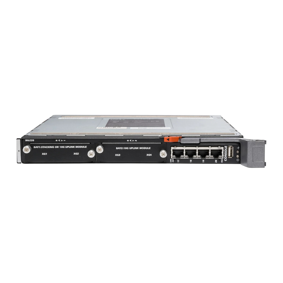
- Page 54 PowerConnect M6220 Front Panel The PowerConnect M6220 front panel provides four 10/100/1000 Base-T RJ-45 ports. The front panel has two 10-gigabit bays that can support Stacking, CX-4, SFP+, XFP, or 10GBase-T modules. Each module provides support for 2 ports. The stacking module can only be used in Bay 1; the 10Gbase-T module can only be used in Bay 2.
-
Page 55: Power Supplies
CLI. Console Redirect The Dell M1000e Server Chassis includes a console redirect feature that allows you to manage each PowerConnect M6220/M6348/M8024 module from a single serial connection to the chassis. For more... -
Page 56: Stacking
Stacking PowerConnect M6348 Stacking You can stack up to 12 PowerConnect M6348, supporting up to 576 1-GB ports. Create a stack by connecting adjacent units using the stacking ports on the bottom of the switch panel. See Figure 4-5. The PowerConnect M6348 and M6220 can not be stacked together. Note: 1. - Page 57 PowerConnect M6220 Stacking You can stack up to 12 PowerConnect M6220 units, supporting up to 240 1-Gb ports. Create a stack by connecting adjacent units using the stacking ports on the top of the switch panel. See Figure 4-5. 1. Install a separately purchased stacking module in Bay 1 of each of the switches in the stack. 2.
-
Page 58: Powerconnect Led Definitions
In Figure 4-4 and Figure 4-5, the stack has six M6220 switches connected through the stacking ports. The first stacking port on each switch is physically connected to the second stacking port on the next switch by using a stacking cable. The first stacking port on switch six is connected to the second stacking port on switch one. - Page 59 Table 4-1. PowerConnect M6348 Power and Status LED Definitions Color Green Blue Amber PowerConnect M8024 LEDs The front panel contains light emitting diodes (LEDs) that provide information about the status of the PowerConnect M8024 unit. Figure 4-7. Front Panel LEDs System Power...
- Page 60 Table 4-2 contains the System Status LED definitions. Table 4-2. PowerConnect M8024 Power and Status LED Definitions Color Green Blue Amber PowerConnect M6220 LEDs The front panel contains light emitting diodes (LEDs) that indicate the status of links for the built-in 1Gb ports and the system status.
- Page 61 Table 4-3. M6220 Status LEDs Definitions Color Green Blue Amber SFP+ Port LEDs Table 4-4 contains SFP+ port LED definitions for the PowerConnect M6220 and M8024. Table 4-4. SFP+ Port LEDs Definitions Color LNK/ACT Solid Green Flashing Green XFP Module Port LEDs The XFP connectors are on the XFP module when it is inserted in the PowerConnect M6220.
- Page 62 Figure 4-9. 10/100/1000 Base-T Port LEDs Speed LEDs Link/Activity Table 4-6 contains 10/100/1000 Base-T port LED definitions. Table 4-6. 10/100/1000 Base-T Port Definitions Color Link/Activity Green Amber Solid Blinking Duplex Green 10 Gb Base-T Module LEDs Each 10 Gb Base-T Module has three LEDs. Table 4-7 contains 10 Gb Base-T port LED definitions for the PowerConnect M6220 and M8024.
- Page 63 Table 4-7. 10 Gb Base-T Module Definitions Color Blinking Green Wrong Bay Solid Red Note: On the PowerConnect M6220, the module must be inserted into Bay 2 to operate. When the module is inserted into Bay 1, it will not operate and the Wrong Bay LED is solid red.
- Page 64 Hardware Description...
-
Page 65: Configuring Dell™ Powerconnect
Performing other functions is described later in this section. Note: Before proceeding, read the release notes for this product. You can download the release notes from the Dell Support website at support.dell.com. Configuring Dell PowerConnect... -
Page 66: Starting The Cli
However, to access the switch through Telnet, at least one user account must be defined. Also, if access is through a Telnet connection, the switch must have a defined IP address, corresponding management access granted, and a workstation connected to the switch before using CLI commands. Configuring Dell PowerConnect... - Page 67 RAM Enter Wizard Initial Configuration: IP Address, Subnetmask, Wizard Configuration Users Basic Security configuration Advanced Configuration: IP Address from DHCP, IP Address from bootp, Security management Hardware Setup Standard Switch Installation Process Advanced Switch Installation Configuring Dell PowerConnect...
-
Page 68: General Configuration Information
The following is required for downloading embedded software and configuring the switch: • ASCII terminal (or emulation) connected to the serial port (cross-cable) in the rear of the unit • Assigned IP address for the switch for switch remote control use with Telnet, SSH, and so forth Configuring Dell PowerConnect... -
Page 69: Booting The Switch
CPU Card ID: 0x508548 Mounting TFFS System ... Device details... volume descriptor ptr (pVolDesc): XBD device block I/O handle: 0x10001 auto disk check on mount: volume write mode: max # of simultaneously open files: 0x1ae4898 NOT ENABLED copyback (DOS_WRITE) Configuring Dell PowerConnect... - Page 70 - # of sectors per root: - max # of entries in root: FAT handler information: ------------------------ - allocation group size: - free space on volume: Configuring Dell PowerConnect NO LABEL ; (in boot sector: 61,076 FAT16 VFAT 8-bit (extended-ASCII)
- Page 71 To return to operational code from the [Boot Menu] prompt, press 1. The following output displays an example configuration. Items such as addresses, versions, and dates may differ for each switch. Operational Code Date: Tue May 26 14:12:20 2009 Uncompressing... Configuring Dell PowerConnect...
- Page 72 # of descriptors for deleted files: # of obsolete descriptors: current volume configuration: - volume label: - volume Id: - total number of sectors: Configuring Dell PowerConnect Processor #0. BSP version 2.0/2. 0x706d770 NOT ENABLED copyback (DOS_WRITE) NO LABEL ; (in boot sector:...
- Page 73 PCI unit 0: Dev 0xb624, Rev 0x12, Chip BCM56624_B1, Driver BCM56624_B0 SOC unit 0 attached to PCI device BCM56624_B1 Adding BCM transport pointers Configuring CPUTRANS TX Configuring CPUTRANS RX st_state(0) = 0x0 st_state(1) = 0x2 FAT16 VFAT 8-bit (extended-ASCII) 4 clusters 44,380,160 bytes Configuring Dell PowerConnect...
- Page 74 However, before configuring the switch, ensure that the software version installed on the switch is the latest version. If it is not the latest version, download and install the latest version. See "Software Download and Reboot." Configuring Dell PowerConnect...
-
Page 75: Configuration Overview
The Easy Setup Wizard guides you in the basic initial configuration of a newly installed switch so that it can be immediately deployed, functional, and completely manageable through the Web, CLI, and the remote Dell Network Manager. After the initial set up, you may enter the system to set up more advanced configuration. - Page 76 The next time the system reboots you are given another opportunity to run the set-up wizard. Functional Flow The following functional flow diagram illustrates the procedures for the Easy Setup Wizard. Configuring Dell PowerConnect...
- Page 77 Auto Config will attempt to download a configuration. Transfer to CLI mode. Request SNMP Community String & Server IP Address Request IP Address, Network Mask, Default Gateway IP Set Simple mode Discard Changes and Restart Wizard Transfer to CLI mode Configuring Dell PowerConnect...
- Page 78 The following example contains the sequence of prompts and responses associated with running an example Dell Easy Setup Wizard session, using the input values listed above. Unit 1 - Waiting to select management unit)> Applying Global configuration, please wait ...
- Page 79 The system is not setup for SNMP management by default. To manage the switch using SNMP (required for Dell Network Manager) you can Set up the initial SNMP version 2 account now. Return later and setup other SNMP accounts. (For more information on setting up an SNMP version 1 or 3 account, see the user documentation).
-
Page 80: Advanced Configuration
If the information is incorrect, select (N) to discard configuration and restart the wizard: [Y/N] y Thank you for using Dell Easy Set up Wizard. You will now enter CLI mode. Applying Interface configuration, please wait... console>... - Page 81 (see below). If additional interface types are to be defined, they must predefined list of be registered with Dell. For example, 1/xg10 identifies the 10-gigabit port 10 on the first unit. Unit# followed by a / symbol and then the...
-
Page 82: M6220, M6348, And M8024Cli Reference Guide
Modifying Switching Port Default Settings • Retrieving an IP Address From a DHCP Server • Configuring an Initial Console Password • Configuring an Initial Telnet Password • Configuring an Initial HTTP Password • Configuring an Initial HTTPS Password Configuring Dell PowerConnect CLI Reference Guide. - Page 83 Head of line blocking prevention Flow Control Back Pressure SwitchA and the CLI is current in the top level of User EXEC mode . Default Setting 1G Auto-negotiation Enabled On (Enabled) config global configuration mode of the interface Configuring Dell PowerConnect...
- Page 84 3. To verify the IP address, enter the show ip interface out-of-band command at the system prompt as shown in the following example. console#show ip interface out-of-band IP Address... 10.27.22.168 Subnet Mask... 255.255.255.0 Default Gateway... 10.27.22.1 ServPort Configured Protocol Current... DHCP Burned In MAC Address... 0063.4802.0011 console# Configuring Dell PowerConnect...
-
Page 85: Security Management And Password Configuration
• When initially logging on to a switch through a console session, enter secret123 at the password prompt. • When changing a switch’s mode to enable, enter secret123 at the password prompt. Configuring Dell PowerConnect... - Page 86 Note: In the Web browser enable SSL 2.0 or greater for the page content to appear. console(config)#crypto certificate 1 generate console(config)#ip https server Note: Http and Https services require level 15 access and connect directly to the configuration level access. Configuring Dell PowerConnect...
-
Page 87: Software Download And Reboot
When the new image is downloaded, it is saved in the area allocated for the other copy of system image (image2, as given in the example). The following is an example of the information that appears: console#copy tftp://10.254.24.64/pc62xxr0v34.stk image Mode... TFTP Set TFTP Server IP... 10.254.24.64 TFTP Path../ Configuring Dell PowerConnect... - Page 88 Management switch has unsaved changes. Are you sure you want to continue? (y/n) 7. Enter y. The following message then displays. Configuration Not Saved! Are you sure you want to reload the stack? (y/n) 8. Enter y to reboot the switch. Configuring Dell PowerConnect...
-
Page 89: Update Bootcode
2 - Start Boot Menu. Select (1, 2): The Boot menu displays and contains the following configuration functions: - Start operational code - Change baud rate - Retrieve event log using XMODEM - Load new operational code using XMODEM Configuring Dell PowerConnect... -
Page 90: Start Operational Code
To change the baud rate from the Boot menu: 1. On the Boot menu, select 2 and press <Enter>. The following prompt displays: [Boot Menu]2 Select baud rate: 1 - 1200 2 - 2400 3 - 4800 4 - 9600 5 - 19200 Configuring Dell PowerConnect 100%... -
Page 91: Retrieve Event Log Using Xmodem
Ready to receive the file with XMODEM/CRC... Ready to RECEIVE File xcode.bin in binary mode Send several Control-X characters to cancel before transfer starts. 2. When using HyperTerminal, click Transfer on the HyperTerminal menu bar. 3. From the Transfer menu, click Send File. Configuring Dell PowerConnect... -
Page 92: Display Operational Code Vital Product Data
Operational Code CRC...0x9B4D Boot Code Version...1 Boot Code Size...0x100000 (1048576) Boot Code Offset...0x7ec0bc (8306876) Boot Code FLASH flag...0 Boot Code CRC...0x1CB8 VPD - rel 0 ver 31 maint_lvl 0 Timestamp - Thu Jun File - pc62xxr0v31.stk Configuring Dell PowerConnect 8 12:51:44 2006... -
Page 93: Update Boot Code
1. On the Boot menu, select 8 and press <Enter>. The following prompt displays: Are you SURE you want to delete backup image : image2 ? (y/n):y Backup image deleted... [Boot Menu] 2. The boot process resumes. Configuring Dell PowerConnect... -
Page 94: Activate Backup Image
Use option 11 to activate the backup image. The active image becomes the backup when this option is selected. To activate the backup image: 1. From the Boot menu, select 11 and press <Enter>. The following message displays: Backup image - image2 activated. 2. The boot process resumes. Configuring Dell PowerConnect... -
Page 95: Password Recovery Procedure
– Network adapter card – ASCII terminal application (for example, Microsoft Plus™ Terminal) – A browser application • The supplied serial cable enable password is not prompted for in this mode. ® Windows ® HyperTerminal or Procomm Configuring Dell PowerConnect... -
Page 96: Initial Connection
Boot menu by selecting 2, if necessary, to run special procedures. Select an option. If no selection in 10 seconds then operational code will start. 1 - Start operational code. 2 - Start Boot Menu. Select (1, 2):2 Configuring Dell PowerConnect... - Page 97 - # of sectors per root: - max # of entries in root: FAT handler information: ------------------------ - allocation group size: - free space on volume: NO LABEL ; (in boot sector: 124,408 FAT16 VFAT 8-bit (extended-ASCII) 4 clusters 44,380,160 bytes Configuring Dell PowerConnect...
- Page 98 Not initialized. remLib: Not initialized. CFI Probe: Found 2x16 devices in x16 mode volume descriptor ptr (pVolDesc): XBD device block I/O handle: 0x10001 auto disk check on mount: Configuring Dell PowerConnect Processor #0. BSP version 2.0/2. 0x706d770 NOT ENABLED...
- Page 99 - file name format: - root dir start sector: - # of sectors per root: - max # of entries in root: FAT handler information: ------------------------ - allocation group size: copyback (DOS_WRITE) 124,408 FAT16 VFAT 8-bit (extended-ASCII) 4 clusters Configuring Dell PowerConnect...
- Page 100 Formatting RamCP: for DOSFS Instantiating RamCP: as rawFs, device = 0x20001 Formatting...OK. (Unit 1 - Waiting to select management unit)> Applying Global configuration, please wait ... Applying Interface configuration, please wait ... console> Configuring Dell PowerConnect 44,380,160 bytes device = 0x20001...
-
Page 101: Device Default Settings
2. Ensure that the management station is connected to the same network as the CMC. For more info see Dell Blade Server CMC User's Guide. 3. Enter the config command at the console to enter the Configuration mode as follows: console#config 4. - Page 102 6. Define a user name and password to allow privileged level 15 switch access for a remote user (HTTP and HTTPS). In this example, the user name Dell, the password is Dell1234, and the privilege level is 15. Privilege levels range from 1 15, with 15 being the highest level.
- Page 103 This ensures that the configuration just completed is the same if the switch is rebooted. console(config)#exit console#copy running-config startup-config The switch is now configured and can be managed through the different options such as Telnet, Web browser interface, and others. Configuring Dell PowerConnect...
-
Page 104: Configuring Secure Management Access (Https)
4. Click Yes to confirm accept the security certification (if it is not authenticated by a third party). The Login Screen displays. 5. Enter the assigned user name and password. The switch Dell OpenManage™ Switch Administrator displays. Configuring Dell PowerConnect... -
Page 105: Configuring System Information
Configuring System Information Overview Use the menus listed on the System page to define the switch’s relationship to its environment. To display the System page, click System in the tree view. The System menu page contains links to the following features: •... -
Page 106: Asset
Defining General Device Information The General menu page contains links to pages that allow you to configure device parameters. Use this page to access the following features: • Asset • System Health • Versions • System Resources • Time Zone Configuration •... - Page 107 Banner motd (message of the day) — Enter the message that appears on the GUI banner (if enabled). • • Banner motd acknowledge — Enable to display the GUI banner motd in the GUI banner. • Sys Object ID — The assigned System Object ID. •...
- Page 108 System Health Use the Health page to view physical device information, including information about the switch’s power and ventilation sources. To display the Health page, click System > General > Health in the tree view. Figure 6-2. Health The Health page contains the following fields: •...
-
Page 109: Versions
Versions Use the Versions page to view information about the software versions currently running. To display the Versions page, click System > General > Versions in the tree view. Figure 6-3. Versions The Versions page contains the following fields: • Unit No. -
Page 110: System Resources
System Resources Use the System Resources page to view information about memory usage and task utilization. To display the System Resources page, click System > General > System Resources in the tree view. Figure 6-4. System Resources The System Resources page contains the following fields: •... -
Page 111: Time Zone Configuration
– One minute – Five minutes Displaying System Resources Using the CLI For information about the CLI commands that perform this function, see the following chapter in the CLI Reference Guide • System Management Commands Time Zone Configuration Use the Time Zone Configuration to configure the time zone difference from Coordinated Universal Time (UTC). -
Page 112: Summer Time Configuration
Configuring Time Zone Settings Using the CLI For information about the CLI commands that perform this function, see the following chapter in the CLI Reference Guide • Clock Commands Summer Time Configuration Use the Summer Time Configuration page to specify a defined summer time duration and offset. To display the Summer Time Configuration page, click System >... - Page 113 Start Week — Select the starting week number. This field displays only when the Recurring check box • is selected. Start Day — Select the starting day number. This field displays only when the Recurring check box is • selected. •...
-
Page 114: Clock Detail
Clock Detail Use the Clock Detail page to set the time and date or view information about the current time, time zone, and summer time settings. To display the Clock Detail page, click System > General > Clock Detail in the tree view. Figure 6-7. -
Page 115: Reset
Reset Use the Reset page to reset the device. To display the Reset page, click System > General > Reset in the tree view. Figure 6-8. Reset The Reset page contains the following fields: • Reset Unit No. — Use to select the device in the stack that needs to be reset. Resetting the Device 1. -
Page 116: Configuring Sntp Settings
Configuring SNTP Settings The device supports the Simple Network Time Protocol (SNTP). SNTP assures accurate network device clock time synchronization up to the millisecond. Time synchronization is performed by a network SNTP server. The device operates only as an SNTP client and cannot provide time services to other systems. -
Page 117: Sntp Global Settings
• If more than one Unicast device responds, synchronization information is preferred from the device with the lowest stratum. • If the servers have the same stratum, synchronization information is accepted from the SNTP server that responded first. MD5 (Message Digest 5) Authentication safeguards device synchronization paths to SNTP servers. MD5 is an algorithm that produces a 128-bit hash. -
Page 118: Sntp Authentication
Receive Broadcast Servers Update — If enabled, listens to the SNTP servers for Broadcast server time • information on the selected interfaces. The device is synchronized whenever an SNTP packet is received, even if synchronization was not requested. • Receive Unicast Servers Update — If enabled, polls the SNTP servers defined on the device for Unicast server time information. - Page 119 Figure 6-10. SNTP Authentication The SNTP Authentication page contains the following fields: SNTP Authentication — If enabled, requires authenticating an SNTP session between the device and • an SNTP server. • Authentication — Type of authentication. System supports MD5 only. •...
- Page 120 Adding an SNTP Authentication Key 1. Open the SNTP Authentication page. 2. Click Add. The Add Authentication Key page displays: Figure 6-11. Add Authentication Key 3. Define the fields as needed. 4. Click Apply Changes. The SNTP authentication key is added, and the device is updated. Displaying the Authentication Key Table 1.
-
Page 121: Sntp Server
Removing an Authentication Key 1. Open the SNTP Authentication page. 2. Click Show All. The Authentication Key Table page displays. 3. Select an Authentication Key Table entry by checking its the Remove check box. 4. Click Apply Changes. The entry is removed, and the device is updated. Defining SNTP Authentication Settings Using CLI Commands For information about the CLI commands that perform this function, see the following chapter in the CLI Reference Guide... - Page 122 The SNTP Servers page contains the following fields: • SNTP Server — Selects user-defined SNTP server IP address from a drop-down menu. Up to eight SNTP servers can be defined by using the Add button. • Encryption Key ID — Specifies user-defined key ID used to communicate between the SNTP server and device.
- Page 123 Displaying the SNTP Servers Table 1. Open the SNTP Servers page. 2. Click Show All. The SNTP Servers Table page displays. Figure 6-15. SNTP Servers Table Modifying an SNTP Server 1. Open the SNTP Servers page. 2. Click Show All. The SNTP Servers Table opens.
-
Page 124: Managing Logs
• Clock Commands. Managing Logs The switch may generate messages in response to events, faults, or errors occurring on the platform as well as changes in configuration or other occurrences. These messages are stored both locally on the platform and forwarded to one or more centralized points of collection for monitoring purposes as well as long term archival storage. - Page 125 To display the Global Settings page, click System > Logs > Global Settings in the tree view. Figure 6-16. Global Settings The Global Settings page contains the following fields: • Logging — Enables device global logs for Cache, File, and Server Logs. All logs which are printed to the console are saved to the log files.
- Page 126 Alert — The second highest warning level. An alert log is saved if there is a serious device malfunction, • such as all device features being down. Critical — The third highest warning level. A critical log is saved if a critical device malfunction •...
- Page 127 RAM Log Table Use the RAM Log Table page to view information about specific RAM (cache) log entries, including the time the log was entered, the log severity, and a description of the log. To display the RAM Log Table, click System > Logs > RAM Log in the tree view. Figure 6-17.
- Page 128 Removing Log Information Using the CLI For information about the CLI commands that perform this function, see the following chapter in the CLI Reference Guide • Syslog Commands. Log File The Log File contains information about specific log entries, including the time the log was entered, the log severity, and a description of the log.
-
Page 129: Remote Log Server Settings
Removing Log Information 1. Open the Log File Table page. 2. Click Clear Log. The log information is removed from the log file table, and the device is updated. Removing Log Information Using the CLI For information about the CLI commands that perform this function, see the following chapter in the CLI Reference Guide •... - Page 130 UDP Port (1 65535) — Sets the UDP port from which the logs are sent. The default value is 514. • – • Facility — A user-defined application from which system logs are sent to the remote server. Only one facility can be assigned to a single server.
- Page 131 Figure 6-20. Add Remote Log Server Settings 3. Complete the fields in the dialog and click Apply Changes. The Remote Log Server Settings page displays the server in the Log Server list only after you go back to the Remote Log Server Settings page. Viewing/Removing a Log Server 1.
-
Page 132: Setting The Operational Mode
Working with Remote Server Logs Using the CLI Commands For information about the CLI commands that perform this function, see the following chapter in the CLI Reference Guide • Syslog Commands. Setting the Operational Mode Users with a privilege level of 15 can configure the switch to operate in normal mode or simple mode. By default, the switch operates in normal mode. - Page 133 Figure 6-22. Operational Mode Configuration The Operational Mode Configuration page contains the following fields: • Simple Switch Mode — Enable or disable Simple mode on the switch. When Simple Switch Mode is disabled, the switch operates in the normal mode, and all applicable features described in this User’s Guide are visible.
-
Page 134: Defining Ip Addressing
Figure 6-23. Operational Mode Configuration Confirmation 4. To confirm the mode change, select Yes. 5. Click Apply Changes to change the mode. Changing the Operating Mode Using the CLI Commands For information about the CLI commands that perform this function, see the following chapter in the CLI Reference Guide •... - Page 135 Out of Band Interface Use the Out of Band Interface menu page to assign the Out of Band Interface IP address, the Subnet Mask, the Default Gateway IP address, and to assign the boot protocol. To display the Out of Band Interface page, click System > IP Addressing > Out of Band Interface in the tree view.
-
Page 136: Domain Name Server (Dns)
Defining Out of Band Interface Parameters Using CLI Commands For information about the CLI commands that perform this function, see the following chapter in the CLI Reference Guide • IP Addressing Commands. Domain Name Server (DNS) The Domain Name System converts user-defined domain names into IP addresses. Each time a domain name is assigned, this service translates the name into a numeric IP address. -
Page 137: Default Domain Name
Adding a DNS Server 1. Open the Domain Name Server (DNS) page. 2. Click Add. The Add DNS Server page displays: Figure 6-26. Add DNS Server 3. Define the relevant fields. 4. Click Apply Changes. The new DNS server is defined, and the device is updated. Configuring DNS Servers Using the CLI Commands For information about the CLI commands that perform this function, see the following chapter in the CLI Reference Guide... - Page 138 Figure 6-27. Default Domain Name The Default Domain Name page contains the following field: • Default Domain Name (0 configured, the default domain name is applied to all unqualified host names. Defining DNS Domain Names Using the CLI Commands For information about the CLI commands that perform this function, see the following chapter in the CLI Reference Guide •...
-
Page 139: Host Name Mapping
Host Name Mapping Use the Host Name Mapping page to assign an IP address to a static host name. The Host Name Mapping page provides one IP address per host. To display the Host Name Mapping page, click System > IP Addressing > Host Name Mapping. Figure 6-28. - Page 140 Figure 6-29. Add Static Host Name Mapping 3. Define the relevant fields. 4. Click Apply Changes. The IP address is mapped to the host name, and the device is updated. Displaying the Static Host Name Mapping Table 1. Open the Host Name Mapping page 2.
-
Page 141: Dynamic Host Name Mapping
Mapping an IP Address to Domain Host Names Using the CLI Commands For information about the CLI commands that perform this function, see the following chapter in the CLI Reference Guide • IP Addressing Commands. Dynamic Host Name Mapping Use the Dynamic Host Name Mapping page to view dynamic host entries the switch has learned. To display the Dynamic Host Name Mapping page, click System >... -
Page 142: Arp Table
ARP Table Use the ARP Table page to view ARP parameters for IP interfaces. The ARP table displays the correlation between each MAC address and its corresponding IP address. To display the ARP Table page, click System > IP Addressing > ARP in the tree view. Figure 6-32. -
Page 143: Ipv6 Management Features
IPv6 Management Features The PowerConnect M6220/M6348/M8024 switch software includes several enhancements to the IPv6 management feature. You can assign either an IPv4 or IPv6 address to the management interface. In previous software releases, the management port supported IPv6 addresses, but only when the switch received its IPv6 addressing and gateway definitions through auto-configuration when connected to an IPv6 router on the management network. - Page 144 Change IPv6 Gateway — Select this option to allow the IPv6 Gateway field to be edited. • • IPv6 Gateway — Enter the IPv6 gateway address (do not include a prefix). Use an IPv6 global or link- local address format. •...
-
Page 145: Running Cable Diagnostics
Running Cable Diagnostics Use the Diagnostics menu page to perform virtual cable tests for copper and fiber optics cables. To display the Diagnostics page, click System > Diagnostics in the tree view. Use this page to go to the following feature: •... - Page 146 The Integrated Cable Test for Copper Cables page contains the following fields: • Interface — The interface to which the cable is connected. • Test Result — The cable test results. Possible values are: – No Cable — There is not a cable connected to the port. –...
-
Page 147: Optical Transceiver Diagnostics
Figure 6-36. Integrated Cable Test Results Table Performing Copper Cable Tests Using CLI Commands For information about the CLI commands that perform this function, see the following chapter in the CLI Reference Guide • PHY Diagnostics Commands. Optical Transceiver Diagnostics Use the Optical Transceiver Diagnostics page to perform tests on Fiber Optic cables. - Page 148 Figure 6-37. Optical Transceiver Diagnostics The Optical Transceiver Diagnostics page contains the following fields: • Interface — The port IP address on which the cable is tested. • Temperature — The temperature (C) at which the cable is operating. • Voltage —...
-
Page 149: Managing Device Security
Figure 6-38. Optical Transceiver Diagnostics Table The test runs and displays the Optical Transceiver Diagnostics Table page. Performing Fiber Optic Cable Tests Using CLI Commands For information about the CLI commands that perform this function, see the following chapter in the CLI Reference Guide •... -
Page 150: Access Profile
• RADIUS Accounting Server Statistics • RADIUS Server Statistics • Authorization Network RADIUS • Telnet Server • Denial of Service Access Profile Use the Access Profile page to define a profile and rules for accessing the device. You can limit access to specific management functions, to specific ingress interfaces, and/or to source IP address and/or source IP subnets. - Page 151 Figure 6-39. Access Profile • Access Profile — Shows the Access Profile. • Current Active Access Profile — Shows profile that is activated. • Set Active Access Profile — Activates the access profile. • Remove Profile — When checked, removes an access profile from the Access Profile list. Note: Assigning an access profile to an interface implies that access through other interfaces is denied.
- Page 152 Figure 6-40. Profile Rules Table Adding an Access Profile 1. Open the Access Profile page. 2. Click Add Profile. The Add an Access Profile page displays. Figure 6-41. Add an Access Profile 3. Enter the profile name in the Access Profile Name text box. 4.
- Page 153 Management Method — Select from the dropdown box. The policy is restricted by the management chosen. Interface — Choose the check box for the interface if the policy should have a rule based on the interface. Interface can be a physical interface, a LAG, or a VLAN. Source IP Address —...
- Page 154 Figure 6-42. Add An Access Profile Rule 3. Complete the fields in the dialog: Management Method — Select from the dropdown box. The policy is restricted by the management chosen. Interface — Choose the check box for the interface if the policy should have a rule based on the interface.
-
Page 155: Authentication Profiles
Removing a Rule 1. Open the Access Profile page 2. Click Show All to display the Profile Rules Table page. 3. Select a rule. 4. Check the Remove check box. 5. Click Apply Changes. The rule is removed, and the device is updated. Defining Access Profiles Using CLI Commands For information about the CLI commands that perform this function, see the following chapter in the CLI Reference Guide... - Page 156 Figure 6-43. Authentication Profiles The Authentication Profiles page contains the following fields: Authentication Profile Name Displays lists to which user-defined authentication profiles are added. Use the radio buttons to apply the authentication profile to govern either Login or Enable part of the switch’s operations, and to select one of two available lists: •...
- Page 157 Authentication Method • Optional Methods — User authentication methods. Possible options are: – None — No user authentication occurs. Local — User authentication occurs at the device level; the device checks the user name and – password for authentication. – RADIUS —...
- Page 158 3. Enter the profile name of 1 to 12 characters in the Profile Name field. Note: The profile name should not include spaces. 4. Click Apply Changes. A profile is created. You can activate an authentication profile using the System > Management Security >...
-
Page 159: Select Authentication
Configuring an Authentication Profile Using CLI Commands For information about the CLI commands that perform this function, see the following chapter in the CLI Reference Guide • AAA Commands. Select Authentication After authentication profiles are defined, you can apply them to management access methods. For example, console users can be authenticated by Authentication Profile List 1, while Telnet users are authenticated by Authentication Profile List 2. - Page 160 Secure HTTP and HTTP — Authentication method used for Secure HTTP access and HTTP access, • respectively. Possible field values are: None — No authentication method is used for access. – – Local — Authentication occurs locally. – RADIUS — Authentication occurs at the RADIUS server. –...
- Page 161 TACACS+, Local, None — Authentication first occurs at the TACACS+ server. If – authentication cannot be verified at the TACACS+ server, the session is authenticated locally. If the session cannot be authenticated locally, the session is permitted. Applying an Authentication Method List to Console Sessions 1.
- Page 162 Applying an Authentication Profile to Telnet Sessions 1. Open the Select Authentication page. 2. Select an authentication profile in the Telnet field. 3. Click Apply Changes. Console sessions are assigned authentication profiles. Applying an Authentication Profile to Secure Telnet (SSH) Sessions 1.
-
Page 163: Password Management
Password Management Password management provides increased network security and improved password control. Passwords for SSH, Telnet, HTTP, HTTPS, and SNMP access are assigned security features, including: • Defining minimum password lengths (the minimum password length is 8 when password length- checking is enabled) •... -
Page 164: Local User Database
Enable Password Aging (1 • out, when checked. The field value is from 1 to 365 days. The password aging feature functions only if the switch clock is synchronized to an SNTP server. See the "Clock Commands" section in the Reference Guide for additional information. - Page 165 Figure 6-48. Local User Database The Local User Database page contains the following fields: • User Name — List of users. • Access Level — User access level. The lowest user access level is 1 (readonly), and 15 (readwrite) is the highest.
- Page 166 Adding a User to the Local User Database 1. Open the Local User Database page. 2. Click Add to display the Add User page. The Add a New User page is displayed. Figure 6-49. Add a New User 3. Complete the fields. 4.
-
Page 167: Line Passwords
Removing Users From the Local User Database 1. Open the Local User Database page. 2. Click Show All to display the Local User Table page. 3. Select a User Name. 4. Check Remove. 5. Click Apply Changes. The user is removed, and the device is updated. Assigning Users With CLI Commands For information about the CLI commands that perform this function, see the following chapter in the CLI Reference Guide... - Page 168 Figure 6-51. Line Password The Line Password page contains the following fields: • Line Mode — Drop-down menu specifies device access through a Console, Telnet, or Secure Telnet (SSH) session. • Line Password (8 64 characters) — The line password for accessing the device through a console, –...
-
Page 169: Enable Password
Assigning Line Passwords Using CLI Commands For information about the CLI commands that perform this function, see the following chapter in the CLI Reference Guide • AAA Commands. Enable Password Use the Enable Password page to set a local password to control access to normal and privilege levels. To display the Enable Password page, click System >... -
Page 170: Tacacs+ Settings
Defining Enable Passwords 1. Open the Enable Password page 2. Specify the Enable password. 3. Confirm the Enable password. 4. Click Apply Changes. The Enable password is set. Assigning Enable Passwords Using CLI Commands For information about the CLI commands that perform this function, see the following chapter in the CLI Reference Guide •... - Page 171 Figure 6-53. TACACS+ Settings The TACACS+ Settings page contains the following fields: • Host Name / IP Address — Specifies the TACACS+ Server. • Priority (0 65535) — Specifies the order in which the TACACS+ servers are used. The default is 0. –...
- Page 172 Not Connected — There is not currently a connection between the device and the TACACS+ – server. The fields in the Default Parameters section of the page contain values that are automatically applied to new TACACS+ servers. • Key String (0 128 Characters) —...
-
Page 173: Radius Global Configuration
The TACACS+ Servers Table opens. Figure 6-55. TACACS+ Servers Table Removing a TACACS+ Server from the TACACS+ Servers List 1. Open the TACACS+ Settings page. 2. Click Show All. The TACACS+ Servers Table opens. 3. Select a TACACS+ Servers Table entry. 4. - Page 174 In some networks, the RADIUS server is responsible for assigning traffic to a particular VLAN. The RADIUS enhancements include the Authorization Network RADIUS feature that allows the switch to accept VLAN assignment by the RADIUS server. The RADIUS server maintains a user database, which contains per-user authentication information. RADIUS servers provide a centralized authentication method for: •...
-
Page 175: Radius Server Configuration
Named Authentication Server Groups — The number of authentication server groups configured on • the system. An authentication server group contains one or more configured authentication servers that share the same RADIUS server name. • Named Accounting Server Groups — The number of accounting server groups configured on the system. - Page 176 Figure 6-57. RADIUS Server Configuration The RADIUS Server Configuration page contains the following fields: • RADIUS Server Host Address — Use the drop-down menu to select the IP address of the RADIUS server to view or configure. Click Add to display the Add RADIUS Server page used to configure additional RADIUS servers.
- Page 177 Message Authenticator — Enable or disable the message authenticator attribute for the selected • server. Secret Configured — Indicates whether the shared secret for this server has been configured. • • Status — Indicates whether the selected RADIUS server is currently serving as the active RADIUS server If more than one RADIUS server is configured with the same name, the switch selects one of the servers to be the active server from the group of servers with the same name.
-
Page 178: Radius Accounting Server Configuration
Viewing RADIUS Server Status and Removing a Named Server 1. Open the RADIUS Server Configuration page. 2. Click Show All. The RADIUS Named Server Status page displays. Figure 6-59. RADIUS Server Status 3. To remove a named server, select the check box in the Remove column. 4. - Page 179 Figure 6-60. RADIUS Accounting Server Configuration The RADIUS Accounting Server Configuration page contains the following fields: • RADIUS Accounting Server Host Address — Use the drop-down menu to select the IP address of the accounting server to view or configure. Click Add to display the Add RADIUS Accounting Server page used to configure additional RADIUS servers.
- Page 180 Adding a RADIUS Accounting Server 1. Open the RADIUS Accounting Server Configuration page. 2. Click Add. The Add RADIUS Accounting Server page displays. Figure 6-61. Add RADIUS Accounting Server 3. Enter an IP address and name for the RADIUS accounting server to add. 4.
-
Page 181: Radius Accounting Server Statistics
RADIUS Accounting Server Statistics Use the RADIUS Accounting Server Statistics page to view statistical information for each RADIUS accounting server configured on the system. To access the RADIUS Accounting Server Statistics page, click System > Management Security > RADIUS Accounting Server Statistics in the tree view. Figure 6-63. -
Page 182: Radius Server Statistics
Pending Requests — The number of RADIUS Accounting-Request packets destined for this server • that have not yet timed out or received a response. Timeouts — The number of accounting timeouts to this server. • • Unknown Types — The number of RADIUS packets of unknown type which were received from this server on the accounting port. -
Page 183: Authorization Network Radius
Access Requests — The number of RADIUS Access-Request packets sent to this server. This number • does not include retransmissions. Access Retransmissions — The number of RADIUS Access-Request packets retransmitted to this • server. • Access Accepts — The number of RADIUS Access-Accept packets, including both valid and invalid packets, that were received from this server. - Page 184 Figure 6-65. Authorization Network RADIUS The Authorization Network RADIUS page contains the following field: • Admin Mode— Enables or disables the ability of the switch to accept VLAN assignment from the RADIUS server. Configuring System Information...
-
Page 185: Telnet Server
Telnet Server Use the Telnet Server page to enable or disable telnet service on the switch or to modify the telnet port. To display the Telnet Server page, click System > Management Security > Telnet Server. Figure 6-66. Telnet Server The Telnet Server page contains the following fields: •... -
Page 186: Denial Of Service
Configuring the Telnet Server Using CLI Commands For information about the CLI commands that perform this function, see the following chapter in the CLI Reference Guide • Telnet Server Commands Denial of Service Denial of Service refers to the exploitation of a variety of vulnerabilities which would interrupt the service of a host or make a network unstable. - Page 187 Denial of Service Min TCP Hdr Size — Specify the minimum TCP header size allowed. If First • Fragment DoS prevention is enabled, the switch will drop packets that have a TCP header smaller then this configured value. • Denial of Service TCP Fragment — Enabling TCP Fragment DoS prevention causes the switch to drop packets that have an IP fragment offset equal to one.
-
Page 188: Captive Portal
Captive Portal The Captive Portal (CP) feature allows you to block clients directly connected to the switch from accessing the network until user verification has been established. You can configure CP verification to allow access for both guest and authenticated users. Authenticated users must be validated against a database of authorized Captive Portal users before access is granted. - Page 189 CP Global Configuration From the CP Global Configuration page, you can control the administrative state of the CP feature and configure global settings that affect all captive portals configured on the switch. To configure the global CP settings, click System > Captive Portal > Global Configuration. Figure 6-68.
-
Page 190: Cp Configuration
Authentication Timeout — To access the network through a portal, the client must first enter • authentication information on an authentication Web page. Enter the number of seconds to keep the authentication session open with the client. When the timeout expires, the switch disconnects any active TCP or SSL connection with the client. - Page 191 The CP Configuration page contains the following fields: • Configuration Name — If multiple CP configurations exist on the system, select the CP configuration to view or configure. Use the Add button to add a new CP configuration to the switch. •...
- Page 192 Adding a Captive Portal Configuration 1. Open the Captive Portal Configuration page. 2. Click Add. The Add CP Configuration page displays: Figure 6-70. Add CP Configuration 3. Enter a name for the new CP configuration. 4. Click Apply Changes. The CP configuration is added, and the device is updated. Displaying the CP Configuration Summary 1.
-
Page 193: Cp Web Customization
CP Web Customization When a client connects to the access point, the user sees a Web page. The CP Web Customization page allows you to customize the appearance of that page with specific text and images. To display the CP Web Customization page, click System >... - Page 194 Figure 6-73. CP Web Customization (cont.) The CP Web Customization page contains the following fields: • Captive Portal ID — The drop-down menu lists each CP configured on the switch. To view information about the clients connected to the CP, select it from the list. •...
- Page 195 User Label — Enter the text to display next to the field where the user enters the username. • • Password Label — Enter the text to display next to the field where the user enters the password. • Button Label — Enter the text to display on the button the user clicks to connect to the network. •...
-
Page 196: Local User
Local User You can configure a portal to accommodate guest users and authorized users. Guest users do not have assigned user names and passwords. Authorized users provide a valid user name and password that must first be validated against a local database or RADIUS server. Authorized users can gain network access once the switch confirms the user’s credentials. - Page 197 Removing a Local User 1. Select the user from the Local User Name field. 2. Select the Remove option at the bottom of the page. 3. Click Apply Changes to remove the user. Adding a Local User 1. Open the Local User page. 2.
-
Page 198: User Group
Configuring Users in a Remote RADIUS Server You can use a remote RADIUS server client authorization. You must add all users to the RADIUS server. The local database does not share any information with the remote RADIUS database. The following table indicates the RADIUS attributes you use to configure authorized captive portal clients. - Page 199 Figure 6-77. User Group The User Group page contains the following fields: • Group Name — The menu contains the name of all of the groups configured on the system. The Default user group is configured by default. New users are assigned to the 1-Default user group by default.
-
Page 200: Interface Association
3. Enter a name for the new group. 4. Click Apply Changes. The group is added, and the device is updated. Displaying the User Group Page 1. Open the User Group page. 2. Click Show All. The User Group Summary page displays: Figure 6-79. - Page 201 Figure 6-80. CP Interface Association The Interface Association page contains the following fields: • CP Configuration — Lists the captive portals configured on the switch by number and name. • Interface List — Lists the interfaces available on the switch that are not currently associated with a captive portal.
-
Page 202: Cp Status
CP Status The CP Status page contains a variety of information about the CP feature. From the CP Status page, you can access information about the CP activity and interfaces. To view captive portal status information, click System > Captive Portal > Status. Figure 6-81. -
Page 203: Cp Activation And Activity Status
CP IP Address — Shows the captive portal IP address • • Configured Captive Portals — Shows the number of captive portals configured on the switch. • Supported Captive Portals — Shows the number of supported captive portals in the system. •... -
Page 204: Interface Activation Status
– The associated interfaces do not exist or do not support the CP capability. • Blocked Status — Indicates whether authentication attempts to the captive portal are currently blocked. Use the Block and Unblock buttons to control the blocked status. If the CP is blocked, users cannot gain access to the network through the CP. -
Page 205: Interface Capability Status
Disable Reason — If the selected CP is disabled on this interface, this field indicates the reason, which • can be one of the following: – Interface Not Attached – Disabled by Administrator • Blocked Status — Indicates whether the captive portal is temporarily blocked for authentications. •... -
Page 206: Client Summary
Packets Received Counter — Shows whether the interface supports displaying the number of packets • received from each client. Packets Transmitted Counter — Shows whether the interface supports displaying the number of • packets transmitted to each client. • Session Timeout — Shows whether the interface supports client session timeout. This attribute is supported on all interfaces. -
Page 207: Client Detail
Client Detail The Client Detail page shows detailed information about each client connected to the network through a captive portal. To view detailed information about the clients connected to the switch through the captive portal, click System > Captive Portal > Client Detail. Figure 6-86. -
Page 208: Cp Client Status
Figure 6-87. Interface - Client Status The Interface Client Status page contains the following fields: • Interface — The drop-down menu lists each interface on the switch. To view information about the clients connected to a CP on this interface, select it from the list. •... -
Page 209: Defining Snmp Parameters
Configuration Name — The drop-down menu lists each CP configured on the switch. To view • information about the clients connected to the CP configuration, select the CP configuration name from the list. • MAC Address — Identifies the MAC address of the client. •... -
Page 210: Snmp Global Parameters
• Traps Authentication or Privacy Keys are modified in the SNMPv3 User Security Model (USM). Use the SNMP page to define SNMP parameters. To display the SNMP page, click System > SNMP in the tree view. SNMP Global Parameters Use the Global Parameters page to enable SNMP and Authentication notifications. To display the Global Parameters page, click System >... -
Page 211: Snmp View Settings
2. Type desired hexadecimal ID into the Local Engine ID field. 3. Click Apply Changes. The new Local Engine ID is set, and the device is updated. Using Default SNMP Engine ID 1. Open the Global Parameters page 2. Click the Use Default check box. 3. - Page 212 Figure 6-90. SNMP View Settings The SNMP View Settings page contains the following fields: • View Name — Contains a list of user-defined views. A view name can contain a maximum of 30 alphanumeric characters. • OID Subtree — Specifies a valid SNMP OID string that can include meta characters like *. View Type —...
- Page 213 Figure 6-91. Add View 3. Define the relevant fields. 4. Click Apply Changes. The SNMP view is added, and the device is updated. Displaying the View Table 1. Open the SNMP View Settings page 2. Click Show All. The View Table page displays: Figure 6-92.
-
Page 214: Access Control Group
Removing SNMP Views 1. Open the SNMP View Settings page 2. Click Show All. The View Table page displays. 3. Select an SNMP view. 4. Check the Remove check box. 5. Click Apply Changes. The SNMP view is removed, and the device is updated. Defining SNMP Views Using CLI Commands For information about the CLI commands that perform this function, see the following chapter in the CLI Reference Guide... - Page 215 Figure 6-93. Access Control Group The Access Control Group page contains the following fields: • Group Name — Contains a list of user-defined groups to which access control rules are applied. A group name can contain a maximum of 30 alphanumeric characters. •...
- Page 216 Read — Select a view that restricts management access to viewing the contents of the agent. If no – view is selected, all objects except the community-table, SNMPv3 user and access tables can be viewed. – Write — Select a view that permits management read-write access to the contents of the agent. –...
-
Page 217: Snmpv3 User Security Model (Usm)
Figure 6-95. Access Table Removing a Group 1. Open the Access Control Configuration page. 2. Click Show All. The Access Table opens. 3. Select a group. 4. Check Remove. 5. Click Apply Changes. The group is removed, and the device is updated. Defining SNMP Access Control Using CLI Commands For information about the CLI commands that perform this function, see the following chapter in the CLI Reference Guide... - Page 218 Figure 6-96. SNMPv3 User Security Model (USM) The SNMPv3 User Security Model (USM) page contains the following fields: • User Name — Contains a list of user-defined user names. • Group Name — Contains a list of user-defined SNMP groups. SNMP groups are defined in the Access Control Group page.
- Page 219 Privacy — Specifies whether or not the authentication key is to be used. Choose one of the following • values: None — Do not use an authentication key. – – des — Use a CBC-DES Symmetric Encryption Password for the authentication key. –...
- Page 220 Figure 6-98. Add Remote User 3. Define the relevant fields. 4. Click Apply Changes. 5. The user is added to the group, and the device is updated. Viewing the User Security Model Table 1. Open the SNMPv3 User Security Model (USM) page. 2.
-
Page 221: Communities
Removing a User Security Model Table Entry 1. Open the User Security Model page. 2. Click Show All. The User Security Model Table page displays. 3. Select an entry. 4. Check the Remove check box. 5. Click Apply Changes. The entry is removed, and the device is updated. Defining SNMP Users Using CLI Commands For information about the CLI commands that perform this function, see the following chapter in the CLI Reference Guide... - Page 222 Figure 6-100. SNMPv1, 2 Community The SNMPv1, 2 Community page contains the following fields: • Community String — Contains a list of user-defined community strings that act as a password and are used to authenticate the SNMP management station to the device. A community string can contain a maximum of 20 characters.
- Page 223 Adding a New Community 1. Open the SNMPv1, 2 Community page. 2. Click Add. The Add SNMPv1,2 Community page displays: Figure 6-101. Add SNMPv1,2 Community 3. Complete the relevant fields. In addition to the fields in the SNMPv1, 2 Community page, the Add SNMPv1,2 Community page contains the All (0.0.0.0) field, which indicates that the community can be used from any management station.
-
Page 224: Notification Filter
Figure 6-102. Basic and Advanced Table Removing Communities 1. Open the SNMPv1, 2 Community page. 2. Click Show All. The Basic and Advanced Table page displays. 3. Select a community and check the Remove check box. 4. Click Apply Changes. The community entry is removed, and the device is updated. - Page 225 Figure 6-103. Notification Filter The Notification Filter page contains the following fields: Notification Filter Name — Contains a list of user-defined notification filters. A notification filter • name can contain a maximum of 30 characters. • New Object Identifier Tree — Displays the OID configured for the selected filter. This field can be edited.
- Page 226 Figure 6-104. Add Filter 3. Define the relevant fields. 4. Click Apply Changes. The new filter is added, and the device is updated. Displaying the Filter Table 1. Open the Notification Filter page. 2. Click Show All. The Filter Table page appears, which displays all of the filters configured for the selected filter name: Figure 6-105.
-
Page 227: Notification Recipients
Configuring Notification Filters Using CLI Commands For information about the CLI commands that perform this function, see the following chapter in the CLI Reference Guide • SNMP Commands. Notification Recipients Use the Notification Recipients page to view information for defining filters that determine whether traps are sent to specific users, and the trap type sent. - Page 228 Figure 6-106. Notification Recipients The Notification Recipients page contains the following fields: • Recipient IP — Contains a user-defined list of notification recipients IP addresses. • Notification Type — The type of notification sent. The possible field values are: Trap — Traps are sent. –...
- Page 229 Security Level — The security level attached to notifications. The possible field values are: – • NoAu NoPriv — The packet is neither authenticated nor encrypted. • Auth NoPriv — The packet is authenticated. • Auth Priv — The packet is both authenticated and encrypted. •...
- Page 230 4. Click Apply Changes. The notification recipient is added, and the device is updated. the Notification Recipients Tables Displaying 1. Open Notification Recipients page. 2. Click Show All. The Notification Recipient Tables page opens: Figure 6-108. Notification Recipient Tables Removing Notification Recipients 1.
-
Page 231: File Management
File Management Use the File Management menu page to manage device software, the image file, and the configuration files. In addition to a TFTP server, the file management feature has been enhanced to allow file uploads and downloads by using an HTTP session (in other words, by using your web browser). Configuration file transfers are also permitted by using Secure Copy (SCP) and SSH File Transfer Protocol (SFTP). -
Page 232: Active Images
Image Description — A field 0-128 characters in length that displays an image description of the file. • • Size — Displays the size of the specified file in bytes. • Remove — Select to remove the specified file. • Flash Memory Details —... - Page 233 Figure 6-111. File Download The File Download page contains the following fields: File Type — Select the type of file to be downloaded. Possible filetypes are: • Firmware — Downloads the active image. SSH-1 RSA Key File — SSH-1 Rivest-Shamir-Adleman (RSA) Key File •...
- Page 234 Transfer Mode — Select the file transfer mode for the configuration to download. The options are: • – TFTP — Trivial File Transfer Protocol – SFTP — SSH File Transfer Protocol – SCP — Secure Copy – HTTP — Download files of various types to the switch using an HTTP session (in other words, by using your web browser).
-
Page 235: File Upload
Downloading Files Using CLI Commands For information about the CLI commands that perform this function, see the following chapter in the CLI Reference Guide • Configuration and Image Files Commands. File Upload Use the File Upload to Server page to upload configuration (ASCII), image (binary), operational log, and startup log files from the device to the server. -
Page 236: Copy Files
TFTP — Trivial File Transfer Protocol – – SFTP — SSH File Transfer Protocol – SCP — Secure Copy – HTTP— Hypertext Transfer Protocol Upload Upload contains the following fields: • Server Address — The server IP address to which the selected file is uploaded. •... - Page 237 Figure 6-113. Copy Files The Copy Files page contains the following fields: • Copy Master Firmware — Specifies that a software image file should be copied. • Destination — The destination unit(s) (within the stack) to which the file is copied. Select from the menu one of the following values: –...
-
Page 238: Defining Advanced Settings
Startup Config — The startup configuration file. – – Backup Config — The backup configuration file. • Restore Configuration Factory Default — Select the radio button and click Apply Changes to restore all configuration structures to the defaults. Defining Advanced Settings Use Advanced Settings to set miscellaneous global attributes of the device. - Page 239 Use the Auto Configuration page to enable the switch to be automatically configured when it is initialized and cannot find a configuration file. With Auto Configuration enabled, the switch obtains an IP address and downloads a configuration file from a TFTP server. NOTE: The Auto Configuration process requires the DHCP client on the switch to be enabled by default.
-
Page 240: Defining Stacking
Stack Port Counters • Stack Port Diagnostics NOTE: The PowerConnect M8024 does not support stacking. Stacking Standby You can now select a unit in the stack to be the Standby switch. The unit configured as the Standby switch becomes the stack manager if the current manager fails. To remove the selected unit as the Standby switch, click Delete. - Page 241 Figure 6-115. Unit Configuration The Unit Configuration page contains the following fields: • Switch ID — Specifies unit to be configured. • Change Switch ID to — Changes the unit number of the selected unit. • Management Status — Shows whether the selected unit is a Management Unit or a Stack Member. •...
-
Page 242: Stack Summary
Plugged-in Model Identifier — A 16-byte character string to identify the plugged-in model of the • selected unit. Switch Status — Displays the status of the selected unit. The possible values are: • – OK — The unit is in place and functioning. –... -
Page 243: Supported Switches
– OPR Standby — Indicates that this unit is operating as the Standby Unit and the configured Standby Unit is not part of the stack. – CFG Standby — Indicates that the unit is configured as the Standby Unit. The unit configured as the Standby switch becomes the stack manager if the current manager fails. - Page 244 Figure 6-117. Supported Switches The Supported Switches page contains the following fields: • Supported Switches — Drop-down list permits selection of switches supported. • Switch Index — Specifies the index into the database of the supported switch types. • Switch Type — Hardware ID given to the switch. Switch Model ID —...
-
Page 245: Stack Port Summary
Viewing Supported Switches Using the CLI Commands For information about the CLI commands that perform this function, see the following chapter in the CLI Reference Guide: • System Management Commands Stack Port Summary Use the Stack Port Summary page to view the stackable ports present. This screen displays the unit, the stackable interface, the configured mode of the interface, the running mode as well as the link status and link speed of the stackable port. -
Page 246: Stack Port Counters
Link Status — Indicates whether or not the stack interface for each unit is operating. • • Link Speed (Gb/s) — Indicates the nominal speed of each unit’s link. Viewing Stack Port Summary Using the CLI Command For information about the CLI commands that perform this function, see the following chapter in the CLI Reference Guide: •... -
Page 247: Stack Port Diagnostics
Transmit Error Rate (Errors/sec) — Indicates the number of errors transmitted per second. • • Total Errors — Total number of errors transmitted. • Data Rate (Mb/s) — Indicates the speed at which the data is received. • Receive Error Rate (Errors/sec) — Indicates the number of errors received per second. •... -
Page 248: Sflow Agent Summary
• The collector can analyze traffic patterns for whatever protocols are found in the headers (e.g. TCP/IP, IPX, Ethernet, AppleTalk…), which means there is no need for a layer 2 switch to decode and understand all protocols. sFlow Agent Summary Packet Flow Sampling and Counter Sampling are performed by sFlow Instances associated with individual data sources within the sFlow Agent. -
Page 249: Sflow Receiver Configuration
MIB Version; Organization; Software Revision where: – MIB Version — 1.3, the version of this MIB. – Organization — Dell Corp. – Revision — 1.0 • Agent Address — The IP address associated with this agent. - Page 250 The sFlow Receiver Configuration page contains the following fields: • Receiver Index — Selects the receiver for which data is to be displayed or configured. The allowed range is 1 to 8. • Receiver Owner String — The entity making use of this sFlowRcvrTable entry. The empty string indicates that the entry is currently unclaimed and the receiver configuration is reset to the default values.
-
Page 251: Sflow Sampler Configuration
Configuring and Viewing sFlow Settings Using CLI Commands For information about the CLI commands that perform this function, see the following chapter in the CLI Reference Guide • sFlow Commands. sFlow Sampler Configuration The sFlow Agent collects a statistical packet-based sampling of the switched flows and sends them to the configured receivers. - Page 252 Figure 6-123. sFlow Sampler Configuration The sFlow Sampler Configuration page contains the following fields: • Sampler DataSource— The sFlow data source for this sFlow sampler. This Agent supports physical ports only. • Receiver Index — The sFlow Receiver for this sFlow sampler. If set to zero, no packets will be sampled. Only active receivers can be set.
-
Page 253: Sflow Poll Configuration
Figure 6-124. sFlow Sampler Summary Configuring and Viewing sFlow Settings Using CLI Commands For information about the CLI commands that perform this function, see the following chapter in the CLI Reference Guide • sFlow Commands. sFlow Poll Configuration The sFlow agent collects time-based sampling of network interface statistics and sends them to the configured sFlow receivers. - Page 254 Figure 6-125. sFlow Poll Configuration The sFlow Poll Configuration page contains the following fields: Poll DataSource— The sFlow Sampler data source for this flow sampler. This Agent supports physical • ports only. Receiver Index — The sFlowReceiver for this sFlow Counter Poller. If set to zero, the poller •...
-
Page 255: Industry Standard Discovery Protocol
Configuring and Viewing sFlow Settings Using CLI Commands For information about the CLI commands that perform this function, see the following chapter in the CLI Reference Guide • sFlow Commands. Industry Standard Discovery Protocol The Industry Standard Discovery Protocol (ISDP) is a proprietary Layer 2 network protocol that inter- ®... - Page 256 Figure 6-127. ISDP Global Configuration The ISDP Global Configuration page contain the following fields: • ISDP Mode — Use this field to enable or disable the Industry Standard Discovery Protocol on the switch. • ISDP V2 Mode — Use this field to enable or disable the Industry Standard Discovery Protocol v2 on the switch.
-
Page 257: Cache Table
other—Indicates that the value is in the form of a platform specific ASCII string containing info – that identifies the device. For example: ASCII string contains serialNumber appended/prepended with system name. Configuring ISDP Using CLI Commands For information about the CLI commands that perform this function, see the following chapter in the CLI Reference Guide •... -
Page 258: Interface Configuration
Protocol Version — Displays the ISDP Protocol Version for the neighbor. • • Last Time Changed — Displays when entry was last modified. Viewing ISDP Cache Table Information CLI Commands For information about the CLI commands that perform this function, see the following chapter in the CLI Reference Guide •... -
Page 259: Isdp Statistics
Figure 6-130. ISDP Interface Summary Configuring ISDP Using CLI Commands For information about the CLI commands that perform this function, see the following chapter in the CLI Reference Guide • ISDP Commands. ISDP Statistics From the ISDP Statistics page, you can view information about the ISDP packets sent and received by the switch. - Page 260 The ISDP Statistics page contain the following fields: • Packets Received — Displays the number of all ISDP protocol data units (PDUs) received. • Packets Transmitted — Displays the number of all ISDP PDUs transmitted. • ISDPv1 Packets Received — Displays the number of v1 ISDP PDUs received. •...
-
Page 261: Configuring Switching Information
Configuring Switching Information Overview This section provides all system operations and general information for network security, ports, address tables, GARP , VLANs, Spanning Tree, Port Aggregation, and Multicast Support. The Switching menu page contains links to the following features: • Configuring Network Security •... -
Page 262: Configuring Network Security
Configuring Network Security Use the Network Security menu page to set network security through port-based authentication, locked ports, DHCP Filtering configuration, and access control lists. To display the Network Security page, click Switching > Network Security in the tree view. The Network Security menu page contains links to the following features: •... - Page 263 Figure 7-1. Dot1x Authentication The Dot1x Authentication page contains the following fields: Global Parameters • Administrative Mode— Permits 802.1X port-based authentication on the switch. The possible field values are: – Enable — Enables 802.1X authentication on the switch. – Disable — Disables 802.1X authentication on the switch. •...
- Page 264 Interface Parameters • Interface — Selects the Unit and Port to be affected. • Guest VLAN — Enables or disables the guest VLAN mode on this interface. To enable the guest VLAN, select the VLAN ID to use as the guest VLAN. All VLANs configured on the system are included in the menu.
- Page 265 Max Users — Set the maximum number of clients supported on the port when MAC-based 802.1X • authentication is enabled on the port. The number of users allowed to authenticate per port ranges from 1 to 16. • Termination Cause — Displays the reason for termination. •...
- Page 266 Figure 7-2. Dot1x Authentication Table 3. Use the horizontal scroll bar or click the right arrow at the bottom of the screen to display the right side of the table. 4. Use the Unit drop-down menu to view the Dot1x Authentication Table for other units in the stack, if they exist.
-
Page 267: Authenticated Users
Changing Administrative Port Control 1. Open the Dot1x Authentication page. 2. Click Show All. The Dot1x Authentication Table displays. 3. Scroll to the right side of the table and select the Edit check box for each port to configure. Change Admin Port Control to Authorized, Unauthorized, or Automode as needed for chosen ports. - Page 268 Port Security The Port Security page is used to enable security on a per-port basis. When a port is locked, only packets with allowable source MAC addresses can be forwarded. All other packets are discarded. A MAC address can be defined as allowable by one of two methods: dynamically or statically. To display the Port Security page, click Switching >...
-
Page 269: Ip Acl Configuration
Viewing the Port Security Table 1. Open the Port Security page. 2. Click Show All. The Port Security Table displays. Figure 7-5. Port Security Table 3. Use the Unit drop-down menu to view the Port Security Table for other units in the stack, if they exist. Defining Multiple Locked Ports 1. - Page 270 Packets can be filtered on ingress or egress. If the filter rules match, then some actions can be taken, including dropping the packet or disabling the port. For example, a network administrator defines an ACL rule that says port number 20 can receive TCP packets. However, if a UDP packet is received the packet is dropped.
- Page 271 Figure 7-7. Add IP ACL 3. Enter the desired ACL Name in the related entry field 4. Click Apply Changes. The IP-based ACL is added, and the device is updated. Removing an IP-based ACL 1. Open the IP ACL Configuration page, and select the ACL to be deleted from the IP ACL drop-down menu.
-
Page 272: Ip Acl Rule Configuration
IP ACL Rule Configuration Use the IP ACL Rule Configuration page to define rules for IP-based ACLs. The access list definition includes rules that specify whether traffic matching the criteria is forwarded normally or discarded. Additionally, you can specify to assign traffic to a particular queue, filter on some traffic, change VLAN tag, shut down a port, and/or redirect the traffic to a particular port. - Page 273 Action — Selects the ACL forwarding action. Choose from the drop-down menu options to apply a • forwarding action. Possible values are: Permit — Forwards packets which meet the ACL criteria. – – Deny — Drops packets which meet the ACL criteria. •...
- Page 274 Service Type fields Select one of the following three Match fields to use in matching packets to ACLs: • IP DSCP — Matches the packet DSCP value to the rule. Either the DSCP value or the IP Precedence value is used to match packets to ACLs. –...
-
Page 275: Mac Acl Configuration
• ACL Commands MAC ACL Configuration The MAC ACL Configuration page allows network administrators to define a MAC-based ACL. For an explanation of ACLs, see "IP ACL Configuration." To display the MAC ACL Configuration page, click Switching > Network Security > Access Control Lists >... - Page 276 Figure 7-11. Add MAC ACL 3. Enter the desired MAC ACL Name in the entry field 4. Click Apply Changes. The MAC-based ACL is added, and the device is updated. Removing a MAC-based ACL 1. Open the MAC ACL Configuration page, and select the ACL to be removed from the MAC ACL drop-down menu.
-
Page 277: Mac Acl Rule Configuration
MAC ACL Rule Configuration Use the MAC ACL Rule Configuration page to define rules for MAC-based ACLs. The access list definition includes rules that specify whether traffic matching the criteria is forwarded normally or discarded. A default 'deny all' rule is the last rule of every list. To display the MAC ACL Rule Configuration page, click Switching >... - Page 278 Assign Queue ID — Click the check box to apply this criteria, then enter an identifying number from • 0 to 6. Redirect Interface — Select from the drop-down list of interfaces one that packets meeting this rule • can be redirected to. •...
-
Page 279: Ipv6 Access Control Lists
Adding a New Rule to a MAC-based ACL 1. Open the MAC ACL Rule Configuration page. 2. Select the desired ACL from the MAC ACL drop-down menu. 3. Specify Create New Rule for Rule ID. 4. Enter a new ID number. 5. - Page 280 Figure 7-14. IPv6 ACL Configuration The IPv6 ACL Configuration page contains the following fields: • IPv6 ACL Name — Specify an IPv6 ACL name string which includes alphanumeric characters only. The name must start with an alphabetic character. This field displays the name of the currently selected IPv6 ACL if any ACLs have already been created.
-
Page 281: Ipv6 Acl Rule Configuration
4. Click Apply Changes. Displaying IPv6 ACLs 1. Open the IPv6 ACL Configuration page. 2. Click Show All. All IP ACLs and their related data display in the IPv6 ACL Table. Figure 7-16. IPv6 ACL Table The Summary page has the following fields: IPv6 ACL Name —... - Page 282 To display the IPv6 ACL Rule Configuration page, click Switching > Network Security > Access Control Lists > IPv6 Access Control Lists > Rule Configuration in the navigation menu. Figure 7-17. IPv6 ACL - Rule Configuration The IPv6 ACL Configuration page contains the following fields: •...
- Page 283 Mirror Interface — Specifies the egress interface where the matching traffic stream is copied, in • addition to it being forwarded normally by the device. This field cannot be set if a Redirect Interface is already configured for the ACL rule. •...
- Page 284 IPv6 DSCP Service — Specify the IP DiffServ Code Point (DSCP) value, which is defined as the high- • order six bits of the Service Type octet in the IPv6 header. This is an optional configuration. Enter an integer from 0 to 63. The IPv6 DSCP can be selected from one of the DSCP keywords in the menu. To specify a DSCP by its numeric value, select the Other option in the menu, and a text box displays for entering the numeric value.
-
Page 285: Acl Bind Configuration
ACL Bind Configuration When an ACL is bound to an interface, all the rules that have been defined are applied to the selected interface. Use the ACL Bind Configuration page to assign ACL lists to ACL Priorities and Interfaces. From the Web interface, you can configure the ACL rule in the ingress or egress direction so that the ACLs implement security rules for packets entering or exiting the port. - Page 286 Assign ACL Priority — Assigns the priority of this ACL. If more than one ACL is applied to an – interface, then the match criteria for the highest priority ACLs are checked first. Assigning an ACL to an Interface 1. Open the ACL Bind Configuration page. 2.
-
Page 287: Configuring Ports
Configuring Ports The Ports menu page provides links for configuring port functionality, including advanced features such as storm control and port mirroring, and for performing virtual port tests. To display the page, click Switching > Ports in the tree view. The Ports menu page contains links to the following features: •... - Page 288 Enabling Ingress Backpressure 1. Open the Ports Global Parameters page. 2. Select Enable from the drop-down menu in the Flow Control field. 3. Click Apply Changes. 4. Ingress backpressure is now enabled. Configuring Flow Control Using the CLI Commands For information about the CLI commands that perform this function, see the following chapter in the CLI Reference Guide •...
- Page 289 Current Port Speed — Displays the actual synchronized port speed (bps). • Admin Port Speed — Forces the port speed to the selected value (10M, 100M, or 10000M).For the PowerConnect M8024, the only available speed is 10000M. • Maximum Frame Size (1518–9216)— Specifies the threshold beyond which packets exceeding this size are dropped.
- Page 290 Full — Indicates that the interface supports transmission between the switch and the client in – both directions simultaneously. Current Duplex Mode — Displays the synchronized port duplex mode. • • Auto Negotiation — Enables Auto Negotiation on the port. Auto Negotiation is a protocol between two link partners that enables a port to advertise its transmission rate, duplex mode, and flow control abilities to its partner.
- Page 291 Defining Port Parameters 1. Open the Port Configuration page. 2. Select a unit and port in the Unit and Port fields. 3. Define the available fields on the screen. 4. Click Apply Changes. The port parameters are saved to the switch. Displaying the Port Table 1.
- Page 292 Modifying Port Configuration Settings for Multiple Ports 1. Open the Port Configuration page. 2. Click Show All. The Port Configuration Table displays. 3. Click Edit for each Port to modify. 4. Edit the Port Configuration fields as needed. 5. Click Apply Changes. The Port Configuration settings are modified, and the device is updated.
- Page 293 The Protected Port Configuration page contains the following fields: • Port — Specifies the Unit and Port for which port parameters are defined. • Protected Group ID — Drop-down menu used to assign a port to Group 0, 1, or 2. •...
-
Page 294: Lag Configuration
Figure 7-24. Add Protected Port Use the drop-down menu to assign the numeric designation 0, 1, or 2 to the Protected Group ID. 4. Enter a Protected Group Name (1–32 characters). 5. Click Apply Changes. The Protected Group settings are copied, and the device is updated. Configuring Protected Ports With CLI Commands For information about the CLI commands that perform this function, see the following chapter in the CLI Reference Guide... - Page 295 LAG — Contains a list of LAG numbers. • • LAG Type — The port types that comprise the LAG. • Description (0–64 Characters) — Description of the port. • Admin Status — Enables or disables traffic forwarding through the selected LAG. •...
-
Page 296: Storm Control
5. Admin Status and Description can now be edited as needed. 6. Click Apply Changes. The LAG parameters are saved to the switch. Configuring LAGs with CLI Commands For information about the CLI commands that perform this function, see the following chapter in the CLI Reference Guide •... - Page 297 Multicast — If the rate of L2 multicast traffic ingressing on an interface increases beyond the – configured threshold, the traffic will be dropped. Unknown Unicast — If the rate of unknown L2 unicast (destination lookup failure) traffic – ingressing on an interface increases beyond the configured threshold, the traffic will be dropped. •...
-
Page 298: Configuring Traffic Mirroring
Modifying Broadcast Control 1. Open the Storm Control interface. 2. Click Show All. The Storm Control Settings Table displays. 3. Check Edit for each port that Broadcast Control is to be modified. 4. Edit Broadcast Control as needed. 5. Click Apply Changes. The storm control port parameters are saved to the switch. - Page 299 Figure 7-29. Port Mirroring The Port Mirroring page contains the following fields: Session — Specifies the monitoring session. • • Admin Mode — Enables or Disables the port mirroring. • Destination Port — Select the port to which port traffic may be copied. •...
- Page 300 Figure 7-30. Add Source Port 3. Configure the following fields: Session — Select the session to monitor. Source Port —Select the unit and port from which traffic is mirrored. Up to four source ports can be mirrored to a destination port. Type —...
-
Page 301: Flow Based Mirroring
Configuring a Port Mirroring Session Using CLI Commands For information about the CLI commands that perform this function, see the following chapter in the CLI Reference Guide • Port Monitor Commands Flow Based Mirroring The flow based mirroring feature builds upon the DiffServ component in QoS. In QoS, the user creates traffic classes to define match criteria, then policies to define the action to be taken on that traffic class. -
Page 302: Configuring Address Tables
Copying Mirroring to a Destination Port 1. Open the Flow Based Mirroring page. 2. Specify Policy Name and Member Class, and select the destination unit and port to be affected in Copy to Interface. 3. Click Apply Changes. The flow-based mirroring details are copied to the specified port, and the device is updated. Configuring Flow-based Mirroring Using CLI Commands For information about the CLI commands that perform this function, see the following chapter in the CLI Reference Guide... - Page 303 Figure 7-32. Static MAC Address The Static MAC Address page contains the following fields: • Interface — Specifies the Unit and Port or LAG to which the static MAC address is applied. To view addresses for a different Unit/Port or LAG, change the Interface listed here. •...
- Page 304 Figure 7-33. Adding Static MAC Address 3. Complete the fields as needed. 4. Click Apply Changes. The new static address is added to the Static MAC Address Table, and the device is updated. Modifying a Static Address in the Static MAC Address Table 1.
-
Page 305: Dynamic Address Table
Removing a Static Address from the Static Address Table 1. Open the Static MAC Address page 2. Click Show All to display the Static MAC Address Table. 3. Check the Remove check box for the address to be removed. 4. Click Apply Changes. The static address is deleted, and the device is updated. - Page 306 Figure 7-35. Dynamic Address Table The Dynamic Address Table contains the following fields: • Address Aging (10–1000000) — Specifies aging time in seconds before a dynamic MAC address is erased. The default value is 300 seconds. • Clear Table — Clears all dynamic MAC address data from the table when checked and Apply Changes is clicked.
-
Page 307: Configuring Garp
Interface — Displays the port number. • Defining the Aging Time 1. Open the Dynamic Address Table page. 2. Define the Address Aging field. 3. Click Apply Changes. The aging time is modified, and the device is updated. Querying the Dynamic Address Table 1. - Page 308 Figure 7-36. GARP Timers The GARP Timers page contains the following fields: • Interface — Specifies the Unit and Port or LAG on which the GARP timer is enabled. • GARP Join Timer (10–100) — Displays time, in centiseconds, that PDUs are transmitted. The possible field value is 10-100.
- Page 309 Figure 7-37. GARP Timers Table 3. Use the Unit drop-down menu to view the GARP Timers Table for other units in the stack, if they exist. Copying GARP Timers Settings 1. Open the GARP Timers page. 2. Click Show All. The GARP Timers Table displays.
-
Page 310: Configuring The Spanning Tree Protocol
Defining GARP Timers Using CLI Commands For information about the CLI commands that perform this function, see the following chapter in the CLI Reference Guide • GVRP Commands Configuring the Spanning Tree Protocol The Spanning Tree Protocol (STP) provides a tree topology for any arrangement of bridges. STP also provides one path between end stations on a network, eliminating loops. - Page 311 Figure 7-38. Spanning Tree Global Settings The STP Global Settings page contains the following fields: • Spanning Tree Status — Enables or disables RSTP, STP, or MSTP on the switch. STP Operation Mode — Specifies the STP mode by which STP is enabled on the switch. Possible •...
-
Page 312: Stp Port Settings
Bridge Settings • Priority — Specifies the bridge priority value. When switches or bridges are running STP, each are assigned a priority. After exchanging BPDUs, the switch with the lowest priority value becomes the root bridge. Valid values are from 0–61440. The default value is 32768. •... - Page 313 Figure 7-39. STP Port Settings The STP Port Settings page contains the following fields: • Select a Port — Specifies the Unit and Port on which STP is enabled. • STP — Enables or disables STP on the port. • Port Fast —...
- Page 314 Blocking — The port is currently blocked and cannot be used to forward traffic or learn MAC – addresses. Listening — The port is currently in the listening mode. The port cannot forward traffic nor can it – learn MAC addresses. –...
-
Page 315: Stp Lag Settings
Displaying the STP Port Table and Configuring STP Port Settings 1. Open the STP Port Settings page. 2. Click Show All. The STP Port Table displays. Figure 7-40. STP Port Table 3. Use the Unit drop-down menu to view the STP Port Table for other units in the stack, if they exist. 4. - Page 316 Figure 7-41. STP LAG Settings The STP LAG Settings page contains the following fields: • Select a LAG — Specifies the LAG number for which you want to modify STP settings. • STP — Enables or disables STP on the LAG. Default is enable. •...
- Page 317 Learning — The LAG is in the learning mode and cannot forward traffic, but it can learn new – MAC addresses. Forwarding — The LAG is currently in the forwarding mode, and it can forward traffic and learn – new MAC addresses. –...
-
Page 318: Rapid Spanning Tree
Figure 7-42. STP LAG Table 3. To change the STP settings for one or more LAGs, select the Edit option for the LAG(s), configure the desired settings, and then click Apply Changes. Defining STP LAG Settings Using CLI Commands For information about the CLI commands that perform this function, see the following chapter in the CLI Reference Guide •... - Page 319 Role — Displays the spanning tree role for the port in the STP topology. • • Mode — Displays the administrative mode and if its enabled or disabled. • Fast Link Operational Status — Indicates if Fast Link is enabled or disabled for the port or LAG. If Fast Link is enabled for a port, the port is automatically placed in the forwarding state.
-
Page 320: Mstp Settings
MSTP Settings The Multiple Spanning Tree Protocol (MSTP) supports multiple instances of Spanning Tree to efficiently channel VLAN traffic over different interfaces. MSTP is compatible with both RSTP and STP; a MSTP bridge can be configured to behave entirely as a RSTP bridge or a STP bridge. To display the MSTP Settings page, click Switching >... - Page 321 Included VLANs — Maps the selected VLANs to the selected instance. Every VLAN belongs to one • instance only. Priority (0–61440) — Specifies the switch priority for the selected spanning tree instance. The default • value is 32768. • Bridge ID — Indicates the bridge ID of the selected instance. •...
-
Page 322: Mstp Interface Settings
Defining MST Instances Using CLI Commands For information about the CLI commands that perform this function, see the following chapter in the CLI Reference Guide • Spanning Tree Commands MSTP Interface Settings Use the MSTP Interface Settings page to assign MSTP settings to specific interfaces. To display the MSTP Interface Settings page, click Switching >... - Page 323 Designated — Indicates the port or LAG through which the designated switch is attached to the – LAN. Alternate — Provides an alternate path to the root switch from the interface. – – Backup — Provides a backup path to the designated LAN. Backup ports occur only when two ports are connected in a loop by a point-to-point link.
-
Page 324: Configuring Vlans
Figure 7-48. MSTP Interface Table 3. Use the Unit drop-down menu to view the MSTP Interface Table for other units in the stack, if they exist. 4. To modify the port priority or path cost for one or more interfaces, check Edit for the desired interfaces. -
Page 325: Vlan Membership
Each VLAN in a network has an associated VLAN ID, which appears in the IEEE 802.1Q tag in the Layer 2 header of packets transmitted on a VLAN. An end station may omit the tag, or the VLAN portion of the tag, in which case the first switch port to receive the packet may either reject it or insert a tag using its default VLAN ID. - Page 326 Figure 7-49. VLAN Membership The VLAN Membership page is divided into two sections. The top section contains fields that define the entire VLAN’s membership. The bottom section contains tables that define membership settings for specific Ports and LAGs on this VLAN. Following are the VLAN Membership fields: Show VLAN —...
- Page 327 There are two tables in this section of the page: • Ports — Displays and assigns VLAN membership to ports. To assign membership, click in Static for a specific port. Each click toggles between U, T, and blank. See the following table for definitions. •...
- Page 328 Assigning VLAN Membership to a Port or LAG 1. Open the VLAN Membership page. 2. Select a VLAN from the VLAN ID or VLAN Name drop-down menu. 3. In the VLAN Port Membership Table, assign a value by clicking in the Static row for a specific Port/LAG.
- Page 329 With Double VLAN Tunneling enabled, every frame that is transmitted from an interface has a DVLAN Tag attached while every packet that is received from an interface has a tag removed (if one or more tags are present). Use the Double VLAN Global Configuration page to specify the Double VLAN configuration for all the ports.
- Page 330 Custom — Use this to specify that double-tagged frames will use a custom Ethertype. A custom – Ethertype may be used to make the switch interoperable with specific or non-standard equipment that does not support 802.1 or vMAN values of Ethertype in double-tagged frames. For more information, refer to the list of registered Ethertype values for common protocols.
- Page 331 The Double VLAN Interface Configuration page contains the following fields: • Interface — Select the port or LAG for which you want to display or configure data. • Interface Mode — Enables or disables double VLAN tagging on the selected interface. The default value is Disable.
- Page 332 Copying Double VLAN Parameters 1. Open the Double VLAN Interface Configuration page. 2. Click Show All. The Double VLAN Port Parameters Table displays. 3. Specify the Port you are copying from in Copy Parameters From. 4. Click Copy To for each Interface to receive these parameters. 5.
- Page 333 Figure 7-54. VLAN Port Settings The VLAN Port Settings page contains the following fields: • Ports — Specifies the Unit and Port included in the VLAN. Port VLAN Mode — Indicates the port mode. Possible values are: • – General — The port belongs to VLANs, and each VLAN is user-defined as tagged or untagged (full 802.1Q mode).
- Page 334 Assigning Port Settings 1. Open the VLAN Port Settings page. 2. Select the port to which you want to assign settings from the Unit and Port drop-down menus. 3. Complete the remaining fields on the page. 4. Click Apply Changes. The VLAN port settings are defined, and the device is updated.
- Page 335 Assigning Ports to VLAN Groups Using CLI Commands For information about the CLI commands that perform this function, see the following chapter in the CLI Reference Guide • VLAN Commands VLAN LAG Settings Use the VLAN LAG Settings page to map a LAG to a VLAN. Untagged packets entering the switch are tagged with the LAGs ID specified by the PVID.
- Page 336 Admit Tag Only — The LAG only accepts tagged packets. – – Admit All — Tagged and untagged packets are both accepted by the LAG. • Ingress Filtering — Enables or disables Ingress filtering by the LAG. Ingress filtering discards packets where the VLAN tag does not match the LAG VLAN membership.
- Page 337 Modifying Settings for Multiple LAGs 1. Open the VLAN LAG Settings page. 2. Click Show All. The VLAN LAG Table displays. 3. Click Edit for each LAG to modify. 4. Edit fields as needed. 5. Click Apply Changes. The VLAN LAG settings are modified, and the device is updated. Assigning LAGs to VLAN Groups Using CLI Commands For information about the CLI commands that perform this function, see the following chapter in the CLI Reference Guide...
- Page 338 MAC Address — Specifies MAC Address for a VLAN. • • Bind to VLAN (1–4093) — Specifies VLAN to which the MAC is to be bound. Assigning Bind MAC to VLAN Settings 1. Open the Bind MAC to VLAN page. 2.
-
Page 339: Bind Ip Subnet To Vlan
Removing a MAC - VLAN Entry 1. Open the Bind MAC to VLAN page. 2. Click Show All. The MAC - VLAN Bind Table displays. 3. Check Remove for each entry to remove. 4. Click Apply Changes. The entry/entries are removed, and the device is updated. Binding MACs to VLANs Using CLI Commands For information about the CLI commands that perform this function, see the following chapter in the CLI Reference Guide... - Page 340 The Bind IP Subnet to VLAN page contains the following fields: • IP Address — Specifies packet source IP address. • Subnet Mask — Specifies packet source IP subnet mask. • Bind to VLAN (1–4093) — Specifies VLAN to which the IP Address is assigned. Binding an IP Subnet to a VLAN 1.
-
Page 341: Protocol Group
Removing a MAC - IP Subnet Entry 1. Open the Bind IP Subnet to VLAN page. 2. Click Show All. The IP Subnet - VLAN Bind Table displays. 3. Check Remove for each entry to remove. 4. Click Apply Changes. The entry/entries are removed, and the device is updated. - Page 342 Figure 7-62. Protocol Group The Protocol Group page contains the following fields: • Protocol Group — Displays the name associated with the protocol group ID (up to 16 characters). Create a new group by clicking the Add button. • Protocol — Specifies protocols (in hexadecimal format in the range 0x0600 to 0xffff) associated with this group.
- Page 343 Figure 7-63. Add Protocol Group 3. Enter a new Protocol Group Name and a VLAN ID to associate with this group. 4. Return to the Protocol Group page. 5. Select the Protocol Group that you added, then select the protocol. 6.
-
Page 344: Gvrp Parameters
Removing Multiple Protocols From the Protocol Group Table 1. Open the Protocol Group page. 2. Click Show All. The Protocol Group Table displays. Figure 7-64. Protocol Group Table 3. Check Remove for the protocol groups you want to remove. 4. Click Apply Changes. The protocol is removed, and the device is updated. - Page 345 Figure 7-65. GVRP Global Parameters The GVRP Global Parameters page contains the following fields: GVRP Global Status — Enables or disables GVRP on the switch. GVRP is disabled by default. • • Interface — Specifies the Unit and Port or LAG for which GVRP is enabled. •...
- Page 346 Displaying the GVRP Port Parameters Table 1. Open the GVRP Global Parameters page. 2. Click Show All. The GVRP Port Parameters Table displays. Figure 7-66. GVRP Port Parameters Table 3. Use the Unit drop-down menu to view the GVRP Port Parameters Table for other units in the stack, if they exist.
-
Page 347: Configuring Voice Vlan
Modifying GVRP Parameters for Multiple Ports 1. Open the GVRP Global Parameters page. 2. Click Show All. The GVRP Port Parameters Table displays. 3. Click Edit for each Interface/LAG to modify. 4. Edit the GVRP Port Parameter fields as needed. 5. - Page 348 Figure 7-67. Voice VLAN Configuration The Voice VLAN Configuration page contains the following fields: Voice VLAN Admin Mode — Select the administrative mode for Voice VLAN for the switch from the • drop-down menu. The default is disable. • Port — Select the interface to view or configure. •...
-
Page 349: Aggregating Ports
Configuring Voice VLAN Settings 1. Open the Voice VLAN Configuration page. 2. Configure the settings for the system or for each port. 3. Click Apply Changes. The system parameters are applied, and the device is updated. Configuring Voice VLAN Using CLI Commands For information about the CLI commands that perform this function, see the following chapter in the CLI Reference Guide: Voice VLAN Commands... - Page 350 Figure 7-68. LACP Parameters The LACP Parameters page is divided into two sections: Global Parameters and Port Parameters. Following are the fields on this page: Global Parameters LACP System Priority (1–65535) — Indicates the LACP priority value for global settings. The default •...
- Page 351 Displaying the LACP Parameters Table 1. Open the LACP Parameters page. 2. Click Show All. The LACP Parameters Table displays. Figure 7-69. LACP Parameters Table 3. Use the Unit drop-down menu to view the LACP Parameters Table for other units in the stack, if they exist.
- Page 352 To display the LAG Membership page, click Switching > Link Aggregation > LAG Membership in the tree view. Figure 7-70. LAG Membership The LAG Membership page contains a table with the following fields: LACP — Aggregates a LAG port to LACP membership. For ports with a number in the LAG row, you •...
- Page 353 Adding a LAG Port to an LACP 1. Open the LAG Membership page. 2. Click in the LACP row to toggle the desired LAG port to L. Note: The port must be assigned to a LAG before it can be aggregated to an LACP. 3.
- Page 354 – Source MAC, VLAN, EtherType, SourceModule and Port Id – Destination MAC, VLAN, EtherType, SourceModule and Port Id – Source IP and Source TCP/UDP Port (default) – Destination IP and Destination TCP/UDP Port – Source/Destination MAC, VLAN, EtherType, source MODID/port –...
-
Page 355: Managing Multicast Support
Figure 7-72. LAG Hash Summary The LAG Hash Summary page contains a table with the following fields: • LAGs — Lists the LAG numbers. • Hash Algorithm Type — Shows the type of HASH algorithm for unicast traffic flows that is associated with the LAG. -
Page 356: Multicast Global Parameters
To display the Multicast Support menu page, click Switching > Multicast Support in the tree view. This Multicast Support page contains links to the following features: • Multicast Global Parameters • Bridge Multicast Group • Bridge Multicast Forward • IGMP Snooping •... - Page 357 Enabling Bridge Multicast Filtering on the Switch 1. Open the Multicast Global Parameters page. 2. Select Enable in the Bridge Multicast Filtering field. 3. Click Apply Changes. Bridge Multicast is enabled on the switch. Enabling Multicast Forwarding and/or IGMP Snooping Using CLI Commands For information about the CLI commands that perform this function, see the following chapter in the CLI Reference Guide •...
- Page 358 Figure 7-74. Bridge Multicast Group The Bridge Multicast Group page contains the following fields: • VLAN ID — Selects the VLAN to add a multicast group to or to modify ports on an existing multicast group. Bridge Multicast Address — Identifies the multicast group MAC address/IP address associated with •...
- Page 359 LAGs — Displays and assigns multicast group membership to LAGs. To assign membership, click in • Static for a specific LAG. Each click toggles between S, F, and blank. See the following table for definitions. The following table contains definitions for port/LAG IGMP management settings. Table 7-2.
- Page 360 Figure 7-75. Add Bridge Multicast Group 3. Select the VLAN ID from the drop-down menu. 4. Define the New Bridge Multicast IP or MAC address. 5. In the Bridge Multicast Group tables, assign a setting by clicking in the Static row for a specific port/LAG.
-
Page 361: Bridge Multicast Forward
Removing a Bridge Multicast Group 1. Open the Bridge Multicast Group page. 2. Select the VLAN ID associated with the bridge multicast group to be removed from the drop-down menu. The Bridge Multicast Address and the assigned ports/LAGs display. 3. Check the Remove check box. 4. -
Page 362: Igmp Snooping
Forwarding Mode — Specifies the multicast forwarding mode for the selected VLAN. Possible values • are: Forward Unregistered — Permits the forwarding of IPv4 multicast packets with a destination – address that does not match any of the groups announced in earlier IGMP Membership Reports. –... -
Page 363: General Igmp Snooping
To display the IGMP Snooping page, click Switching > Multicast Support > IGMP Snooping in the tree view. Use this page to go to the following features: • General IGMP Snooping • Global Querier Configuration • VLAN Querier • VLAN Querier Status •... - Page 364 Multicast Router Timeout — Specifies time before aging out a Multicast router entry. The default • value is 300 seconds. Leave Timeout — Specifies time, in seconds, after a port leave message is received before the entry is • aged out. Enter an amount of time for the timeout period, or click Immediate Leave to specify an immediate timeout.
- Page 365 Modifying IGMP Snooping Settings for Multiple Ports, LAGs, or VLANs 1. Open the General IGMP snooping page. 2. Click Show All. The IGMP Snooping Table displays. 3. Click Edit for each Port, LAG, or VLAN to modify. 4. Edit the IGMP Snooping fields as needed. 5.
- Page 366 Figure 7-79. Global Querier Configuration The Global Querier Configuration page contains the following fields: • IP Address— Specifies the Snooping Querier IP Address which will be used as the source address in periodic IGMP queries. This address is used when no address is configured for the VLAN on which the query is being sent.
-
Page 367: Vlan Querier
VLAN Querier Use the VLAN Querier page to specify the IGMP Snooping Querier settings for individual VLANs. To display the VLAN Querier page, click Switching > Multicast Support > IGMP Snooping > VLAN Querier in the tree view. Figure 7-80. VLAN Querier The VLAN Querier page contains the following fields: •... - Page 368 Adding a New VLAN and Configuring its VLAN Querier Settings 1. Open the VLAN Querier page. 2. Click Add. The page refreshes, and the Add VLAN page displays. Figure 7-81. Add VLAN Querier 3. Enter the VLAN ID and, if desired, an optional VLAN name. 4.
-
Page 369: Vlan Querier Status
VLAN Querier Status Use the VLAN Querier Status page to view the IGMP Snooping Querier settings for individual VLANs. To display the VLAN Querier Status page, click Switching > Multicast Support > IGMP Snooping > VLAN Querier Status in the tree view. Figure 7-83. -
Page 370: Mfdb Igmp Snooping Table
Disabled — The Snooping Querier is not operational on the VLAN. The Snooping Querier – transitions to disabled mode when 1) IGMP Snooping is not operational on the VLAN, 2) the querier address is not configured or 3) the network management address is not configured. •... -
Page 371: Mrouter Status
The MFDB IGMP Snooping Table page contains the following fields: • VLAN — Displays the VLAN ID associated with an IGMP group entry in the MFDB table. • MAC Address — Displays the MAC Address associated with an IGMP group entry in the MFDB table. •... -
Page 372: Mld Snooping
MLD Snooping In IPv4, Layer 2 switches can use IGMP snooping to limit the flooding of multicast traffic by dynamically configuring Layer-2 interfaces so that multicast traffic is forwarded to only those interfaces associated with an IP multicast address. In IPv6, MLD snooping performs a similar function. With MLD snooping, IPv6 multicast data is selectively forwarded to a list of ports that want to receive the data instead of being flooded to all ports in a VLAN. - Page 373 The MLD Snooping General page contains the following fields: • Interface — Specifies the Unit and Port or the LAG on which MLD Snooping should be enabled. • Auto Learn — Enable or Disable the ability of the switch to automatically learn about dynamic MLD ports.
-
Page 374: Mld Snooping Global Querier Configuration
MLD Snooping Global Querier Configuration Use the MLD Snooping Global Querier Configuration page to configure the parameters for the MLD Snooping Querier. To display the Global Querier Configuration page, click Switching > Multicast Support > MLD Snooping > Global Querier Configuration in the tree view. Figure 7-88. -
Page 375: Mld Snooping Vlan Querier
MLD Snooping VLAN Querier Use the MLD Snooping VLAN Querier page to specify the MLD Snooping Querier settings for individual VLANs. To display the MLD Snooping VLAN Querier page, click Switching > Multicast Support > MLD Snooping > VLAN Querier in the tree view. Figure 7-89. - Page 376 Figure 7-90. Add VLAN Querier 3. Enter the VLAN ID and, if desired, an optional VLAN name. 4. Complete the fields on the page as needed. 5. Click Apply Changes. The VLAN Querier settings are modified, and the device is updated. Displaying the MLD Snooping VLAN Querier Summary Table 1.
-
Page 377: Mld Snooping Vlan Querier Status
MLD Snooping VLAN Querier Status Use the VLAN Querier Status page to view the MLD Snooping Querier settings for individual VLANs. To display the VLAN Querier Status page, click Switching > Multicast Support > MLD Snooping > VLAN Querier Status in the tree view. Figure 7-92. -
Page 378: Mfdb Mld Snooping Table
Last Querier Address — Displays the IP address of the last querier from which a query was snooped on • the VLAN. Last Querier Version — Displays the MLD protocol version of the last querier from which a query was •... -
Page 379: Configuring The Link Layer Discovery Protocol (Lldp)
VLAN — Displays the VLAN ID associated with an MLD group entry in the MFDB table. • • MAC Address — Displays the MAC Address associated with an MLD group entry in the MFDB table. • Type — Displays the type of entry. Static entries are those that are configured by the user. Dynamic entries are added to the table as a result of a learning process or protocol. - Page 380 Figure 7-94. LLDP Configuration The LLDP Configuration page contains the following fields: Global Settings • Transmit Interval (1–32768) — Specifies the interval at which frames are transmitted. The default is 30 seconds. • Hold Multiplier (2–10) — Specifies multiplier on the transmit interval to assign to TTL. Default is 4. •...
- Page 381 Modifying the LLDP Configuration 1. Open the LLDP Configuration page. 2. Define the fields as needed. 3. Click Apply Changes. LLDP parameters are saved to the switch. Displaying the LLDP Interface Settings Table 1. Open the LLDP Configuration page. 2. Click Show All. The LLDP Interface Settings Table displays.
-
Page 382: Lldp Statistics
Modifying LLDP Interface Settings for Multiple Ports 1. Open the LLDP Configuration page. 2. Click Show All. The LLDP Interface Settings Table displays. 3. Click Edit for each Unit/Port to modify. 4. Edit the LLDP Interface fields as needed. 5. Click Apply Changes. The LLDP Interface settings are modified, and the device is updated. - Page 383 The LLDP Statistics page displays the following statistics: System-wide Statistics • Last Update — Displays the value of system up time the last time a remote data entry was created, modified, or deleted. • Total Inserts — Displays the number of times a complete set of information advertised by a remote switch has been inserted into the table.
-
Page 384: Lldp Connections
LLDP Connections Use the LLDP Connections page to view the list of ports with LLDP enabled. Basic connection details are displayed. To display the LLDP Connections page, click Switching > LLDP > LLDP Connections in the tree view. Figure 7-97. LLDP Connections Table The LLDP Connections page displays the following port details: •... - Page 385 Viewing Details about the LLDP Connections 1. Open the LLDP Connections page. 2. Click the interface in the Local Interface field to view details about that device. The LLDP Connections - Detailed page for the device displays. Figure 7-98. Detailed LLDP Connections 3.
-
Page 386: Creating Link Dependencies
Creating Link Dependencies The link dependency feature provides the ability to enable or disable one or more ports based on the link state of one or more different ports. With link dependency enabled on a port, the link state of that port is dependent on the link state of another port. - Page 387 Figure 7-99. Link Dependency Summary The Link Dependency Summary page contains the following fields: • Group ID — The ID number of the group. • Member Ports — The list of member ports belonging to the group. • Ports Depended On — The list of ports upon which the group depends. •...
- Page 388 Figure 7-100. Link Dependency Group Configuration 3. To add a port to the Member Ports column, click the port in the Available Ports column, and then click the << button to the left of the Available Ports column. Ctrl + click to select multiple ports. 4.
-
Page 389: Dynamic Arp Inspection
Dynamic ARP Inspection Dynamic ARP Inspection (DAI) is a security feature that rejects invalid and malicious ARP packets. DAI prevents a class of man-in-the-middle attacks, where an unfriendly station intercepts traffic for other stations by poisoning the ARP caches of its unsuspecting neighbors. The miscreant sends ARP requests or responses mapping another station’s IP address to its own MAC address. -
Page 390: Dai Interface Configuration
The Dynamic ARP Inspection Global Configuration page contains the following fields: • Validate Source MAC — Select the DAI Source MAC Validation Mode for the switch. If you select Enable, Sender MAC validation for the ARP packets will be enabled. The default is Disable. •... - Page 391 Figure 7-102. Dynamic ARP Inspection Interface Configuration The Dynamic ARP Inspection Interface Configuration page contains the following fields: • Port— Select the port or LAG for which data is to be displayed or configured. • Trust State — Indicates whether the interface is trusted for Dynamic ARP Inspection. If you select Enable, the interface is trusted.
-
Page 392: Dai Vlan Configuration
DAI VLAN Configuration Use the DAI VLAN Configuration page to select the DAI-capable VLANs for which information is to be displayed or configured. To display the DAI VLAN Configuration page, click Switching > Dynamic ARP Inspection > VLAN Configuration in the navigation tree. Figure 7-103. -
Page 393: Dai Acl Configuration
Configuring Dynamic ARP Inspection With CLI Commands For information about the CLI commands that perform this function, refer to the following chapter in CLI Reference Guide • Dynamic ARP Inspection Commands DAI ACL Configuration Use the DAI ARP ACL Configuration page to add or remove DAI ARP ACLs. To display the DAI ARP ACL Configuration page, click Switching >... -
Page 394: Dai Acl Rule Configuration
Displaying the DAI ACL Summary Table and Removing an Entry 1. Open the DAI ACL Configuration page. 2. Click Show All. The Dynamic ARP Inspection ACL Summary table displays. Figure 7-105. Dynamic ARP Inspection ACL Summary 3. To remove an ARP ACL from the list, select the Remove option in the appropriate row, and then click Apply Changes. - Page 395 Figure 7-106. Dynamic ARP Inspection Rule Configuration The Dynamic ARP Inspection Rule Configuration page contains the following fields: • ARP ACL Name — Select the ARP ACL for which information is to be displayed or configured. • Sender IP Address — To create a new rule for the selected ARP ACL, enter in this field the Sender IP Address match value for the ARP ACL.
-
Page 396: Dai Statistics
DAI Statistics Use the DAI Statistics page to display the statistics per VLAN. To display the DAI Statistics page, click Switching > Dynamic ARP Inspection > Statistics in the navigation tree. Figure 7-108. Dynamic ARP Inspection Statistics The Dynamic ARP Inspection Statistics page contains the following fields: •... -
Page 397: Dhcp Snooping
Dropped — The number of not valid ARP packets dropped by DAI. • Configuring Dynamic ARP Inspection With CLI Commands For information about the CLI commands that perform this function, refer to the following chapter in CLI Reference Guide • Dynamic ARP Inspection Commands DHCP Snooping DHCP snooping is a security feature that monitors DHCP messages between a DHCP client and DHCP... -
Page 398: Dhcp Snooping Persistent Configuration
• DHCP Snooping Persistent Configuration • DHCP Snooping Static Bindings Configuration • DHCP Snooping Dynamic Bindings Summary • DHCP Snooping Statistics • IP Source Guard DHCP Snooping Configuration Use the DHCP Snooping Configuration page to control the DHCP Snooping mode on the switch and to specify whether the sender MAC Address for DHCP Snooping must be validated. - Page 399 DHCP Snooping Interface Configuration Use the DHCP Snooping Interface Configuration page to configure the DHCP Snooping settings on individual interfaces. The hardware rate limits DHCP packets sent to the CPU from untrusted interfaces to 64 Kbps. There is no hardware rate limiting on trusted interfaces. To prevent DHCP packets from being used as a DoS attack when DHCP snooping is enabled, the snooping application enforces a rate limit for DHCP packets received on untrusted interfaces.
- Page 400 The DHCP Snooping Interface Configuration page contains the following fields: • Port — Select the interface for which data is to be displayed or configured. • Trust State — If it is enabled, the DHCP snooping application considers the port as trusted. The default is Disable.
- Page 401 DHCP Snooping VLAN Configuration The DHCP snooping application does not forward server messages because they are forwarded in hardware. DHCP snooping forwards valid DHCP client messages received on non-routing VLANs. The message is forwarded on all trusted interfaces in the VLAN. DHCP snooping can be configured on switching VLANs and routing VLANs.
-
Page 402: Dhcp Snooping Persistent Configuration
Figure 7-113. DHCP Snooping VLAN Summary Configuring DHCP Snooping With CLI Commands For information about the CLI commands that perform this function, refer to the following chapter in CLI Reference Guide • DHCP Snooping Commands DHCP Snooping Persistent Configuration Use the DHCP Snooping Persistent Configuration page to configure the persistent location of the DHCP snooping database. - Page 403 Local — Select the Local check box to store the DHCP binding database in the flash memory on – the switch. Remote — Check the Remote check box to store the DHCP binding database on a remote – server. • Remote IP Address —...
- Page 404 If the absolute lease time of the snooping database entry expires, then that entry will be removed. You should take care of the system time to be consistent across the reboots. Otherwise, the snooping entries will not expire properly. If a host sends a DHCP release while the switch is rebooting then, when the switch receives the DHCP discovery or request, the client’s binding will go to the tentative binding as shown in the following figure.
- Page 405 MAC Address — Specify the MAC address for the binding to be added. This is the Key to the binding • database. VLAN ID — Select the VLAN from the list for the binding rule. The range of the VLAN ID is 1 to •...
- Page 406 Figure 7-118. DHCP Snooping Dynamic Bindings Summary The DHCP Snooping Dynamic Bindings Summary page contains the following fields: • Interface — Displays the interface. • MAC Address — Displays the MAC address. VLAN ID — Displays the VLAN ID. • •...
- Page 407 DHCP Snooping Statistics The DHCP Snooping Statistics page displays DHCP snooping interface statistics. To access the DHCP Snooping Statistics page, click Switching > DHCP Snooping > Statistics in the navigation tree. Figure 7-119. DHCP Snooping Statistics The DHCP Snooping Statistics page contains the following fields: •...
-
Page 408: Ip Source Guard
IP Source Guard IP source guard (IPSG) is a security feature that filters IP packets based on source ID. The source ID may either be source IP address or a {source IP address, source MAC address} pair. IPSG is disabled by default. - Page 409 IPSG Binding Configuration Use the IPSG Binding Configuration page displays DHCP snooping interface statistics. To access the DHCP Snooping Statistics page, click Switching > DHCP Snooping > IP Source Guard > IPSG Binding Configuration in the navigation tree. Figure 7-121. IPSG Binding Configuration The IPSG Binding Configuration page contains the following fields: •...
-
Page 410: Dhcp Relay
IPSG Binding Configuration Summary The IPSG Binding Configuration Summary page displays the IPSG Static binding list and IPSG dynamic binding list (the static bindings configured in Binding configuration page). To access the IPSG Binding Configuration Summary page, click Switching > DHCP Snooping > IP Source Guard >... -
Page 411: Dhcp Relay Global Configuration
Before it relays DHCP requests from clients, the switch can add a Circuit ID and a Remote ID. These provide information about the circuit and port number connected to the client. This information is added as suboptions in the DHCP Option 82 packets (see sections 3.1 and 3.2 of RFC3046). The switch removes this option from packets that it relays from L3 Relay agents/DHCP servers to clients. - Page 412 DHCP Relay Interface Configuration Use this page to enable L2 DHCP relay on individual ports. NOTE: L2 DHCP relay must also be enabled globally on the switch. To access this page, click Switching > DHCP Relay > Interface Configuration in the tree view. Figure 7-124.
-
Page 413: Dhcp Relay Interface Statistics
Figure 7-125. DHCP Relay Interface Summary Configuring DHCP Relay With CLI Commands For information about the CLI commands that perform this function, refer to the following chapter in CLI Reference Guide • L2 DHCP Relay Agent Commands DHCP Relay Interface Statistics Use this page to display statistics on DHCP Relay requests received on a selected port. - Page 414 The DHCP Relay Interface Statistics page contains the following fields: • Interface — Select the slot/port to configure this feature on. • Untrusted Server Msgs With Option-82 — If the selected interface is configured in untrusted mode, this field shows the number of messages received on the interface from a DHCP server that contained Option 82 data.These messages are dropped.
-
Page 415: Dhcp Relay Vlan Configuration
DHCP Relay VLAN Configuration You can enable L2 DHCP relay on a particular VLAN. The VLAN is identified by a service VLAN ID (S- VID), which a service provider uses to identify a customer’s traffic while traversing the provider network to multiple remote sites. -
Page 416: Using The Port Aggregator Feature
DHCP Relay Remote-Id — When a string is entered here, if a client sends a DHCP request to the • switch and the client is in a VLAN that corresponds to the selected S-VID, then the switch adds the string to the Remote-ID sub-option of Option 82 in the DHCP request packet. The range is 0-128 alphanumeric characters. -
Page 417: Port Configuration Summary
Port Configuration Summary Use the Port Configuration Summary page to view information about the port members and LACP modes for the aggregator groups. From the Port Configuration Summary page, you can access the Port Configuration page. To display the Port Configuration Summary page, click Switching > Port Aggregator > Port Configuration Summary in the tree view. - Page 418 Configuring Port Aggregator Groups You can assign each port to an aggregator group from the Port Configuration page, which is accessible from the Port Configuration Summary page. By default, all ports are in aggregator group 1. 1. Open the Port Configuration Summary page. 2.
-
Page 419: Group Configuration Summary
Removing Ports from an Aggregator Group 1. Open the Port Configuration Summary page. 2. Select the Remove option for the group with the ports to remove. 3. Click Apply Changes. All ports assigned to the Port Aggregator group are removed from the group and are not assigned to any group. - Page 420 The Group Configuration Summary page contains the following fields: • Group ID — Identifies the aggregator group. • VLAN — Select the VLAN or VLANs that will have the Aggregator Group as a member. An Aggregator Group can be a member of multiple VLANs, but each VLAN can only belong to one Aggregator Group. By default, a VLAN is reserved for each group, starting with VLAN 4022 for group 1.
- Page 421 Duplex — Identifies the group duplex mode, which is either Full or Half. • – Full — Indicates that the group supports transmission between the switch and the client in both directions simultaneously. – Half — Indicates that the group supports transmission between the switch and the client in only one direction at a time.
-
Page 422: Group Vlan Mac Summary
Group VLAN MAC Summary Use the Group VLAN MAC Summary page to view the MAC address table entries for one Port Aggregator group or all groups. To display the Group VLAN MAC Summary page, click Switching > Port Aggregator > Group VLAN MAC Summary in the tree view. -
Page 423: Viewing Statistics And Remote Monitoring
Viewing Statistics and Remote Monitoring Overview This section explains the RMON options available from the Statistics/RMON menu page. These options include viewing statistics in table form, editing and viewing RMON statistics, and charting Port and LAG statistics. The Statistics/RMON menu page provides access to these options through the following menu pages: •... -
Page 424: Table Views
Table Views The Table Views menu page contains links to web pages that display statistics in table form. To display this page, click Statistics/RMON > Table Views in the tree view. Following are the web pages accessible from this menu page: •... - Page 425 The Interface Statistics page contains the following fields: • Interface — Select physical interface (unit, port) or LAG interface for which statistics is displayed. • Refresh Rate — Specifies amount of time that passes before statistics are refreshed. The possible field values are No Refresh, 15, 30 and 60 seconds.
- Page 426 Etherlike Statistics Use the Etherlike Statistics page to display interface statistics. To display the page, click Statistics/RMON > Table Views > Etherlike Statistics in the tree view. Figure 8-2. Etherlike Statistics The Etherlike Statistics page contains the following fields: • Interface —...
- Page 427 Internal MAC Receive Errors — Displays number of internal MAC received errors on the selected • interface. Received Pause Frames — Displays number of received paused frames on the selected interface. • Transmitted Pause Frames — Displays number of transmitted paused frames on the selected interface. Displaying Etherlike Statistics for an Interface 1.
- Page 428 The GVRP Statistics page contains the following fields: • Interface — Select physical interface (unit, port) or LAG interface for which statistics will be displayed. • Refresh Rate — Specifies amount of time that passes before statistics are refreshed. The possible field values are No Refresh, 15, 30, and 60 seconds.
- Page 429 EAP Statistics Use the EAP Statistics page to display information about EAP packets received on a specific port. For more information about EAP, see "Dot1x Authentication." To display the EAP Statistics page, click Statistics/RMON > Table Views > EAP Statistics in the tree view Figure 8-4.
- Page 430 Respond Frames Received — Displays the number of valid EAP Respond frames received on the port. • • Request ID Frames Received — Displays the number of EAP Request ID frames that have been received on the port. • Request Frames Transmitted — Displays the number of EAP Request frames transmitted through the port.
-
Page 431: Utilization Summary
Utilization Summary Use the Utilization Summary page to display interface utilization statistics. To display the page, click Statistics/RMON > Table Views > Utilization Summary in the tree view. Figure 8-5. Utilization Summary The Utilization Summary page contains the following fields: •... - Page 432 Viewing Interface Utilization Statistics Using the CLI Command For information about the CLI commands that perform this function, see the following chapter in the CLI Reference Guide • RMON Commands Counter Summary Use the Counter Summary page to display interface utilization statistics in numeric sums as opposed to percentages.
-
Page 433: Rmon
Received Errors— Displays number of received errors on the interface. • • Transmit Errors — Displays number of transmitted errors from the interface. Setting Refresh Rate 1. Open the Counter Summary page. 2. Select the Refresh Rate from the drop-down menu. Statistics refresh for the displayed interfaces at the selected frequency. - Page 434 RMON Statistics Use the RMON Statistics page to display details about switch use such as packet processing statistics and errors that have occurred on the switch. To display the page, click Statistics/RMON > RMON > Statistics in the tree view. Figure 8-7.
- Page 435 Multicast Packets Received — Displays number of good multicast packets received on the interface • since the switch was last refreshed. CRC & Align Errors — Displays number of CRC and Align errors that have occurred on the interface • since the switch was last refreshed.
- Page 436 RMON History Control Statistics Use the RMON History Control page to maintain a history of statistics on each port. For each interface (either a physical port or a port-channel), you can define how many buckets exist, and the time interval between each bucket snapshot.
- Page 437 Adding a History Control Entry 1. Open the RMON History Control page. 2. Click Add. The Add History Entry page displays. Figure 8-9. Add History Entry 3. Complete the fields on this page and click Apply Changes. The entry is added to the RMON History Control Table. Displaying the RMON History Control Table 1.
- Page 438 Viewing RMON History Control Using the CLI Commands For information about the CLI commands that perform this function, see the following chapter in the CLI Reference Guide • RMON Commands RMON History Table Use the RMON History Table page to display interface-specific statistical network samplings. Each table entry represents all counter values compiled during a single sample.
- Page 439 Drop Events — Displays the total number of events in which packets were dropped by the port due to • lack of resources. Note that this number is not necessarily the number of packets dropped; it is just the number of times this condition has been detected. •...
- Page 440 Viewing RMON History Control Using the CLI Command For information about the CLI commands that perform this function, see the following chapter in the CLI Reference Guide • RMON Commands RMON Event Control Use the RMON Events Control page to define RMON events. Events are used by RMON alarms to force some action when a threshold is crossed for a particular RMON counter.
- Page 441 The RMON Event Control page contains the following fields: • Event Entry — Selects the event. • Community — Specifies the community to which the event belongs. • Description — Describes the user-defined event. • Event Type — Selects the event type. Possible values are: –...
- Page 442 Modifying an RMON Event 1. Open the RMON Event Control page. 2. Click Show All to display the Event Control Table page. 3. Select the Edit check box in for the event entry to change. 4. Modify the fields on the page as needed. 5.
- Page 443 RMON Event Log Use the RMON Event Log page to display a list of RMON events. To display the page, click Statistics/RMON > RMON > Events Log in the tree view. Figure 8-15. RMON Event Log The RMON Event Log page contains the following fields: •...
-
Page 444: Rmon Alarms
RMON Alarms Use the RMON Alarms page to set network alarms. Alarms occur when certain thresholds are crossed for the configured RMON counters. The alarm triggers an event to occur. The events can be configured as part of the RMON Events group. For more information about events, see To display the page, click Statistics/RMON >... - Page 445 Rising Threshold (0–2147483647) — Displays the rising counter value that triggers the rising • threshold alarm. The rising threshold is presented on top of the graph bars. Each monitored variable is designated a color. The default is 100. • Rising Event — Displays the mechanism in which the alarms are reported, including a log, a trap, or both.
- Page 446 Figure 8-17. Add an Alarm Entry 3. Complete the fields on this page as needed. 4. Click Apply Changes. The RMON alarm is added, and the device is updated. Displaying the Alarm Table 1. Open the RMON Alarms page. 2. Click Show All. The left side of the RMON Alarms Table displays.
- Page 447 Removing One Alarm Table Entry 1. Open the RMON Alarms page. 2. Select an entry in the Alarm Entry drop-down menu. 3. Check the Remove check box and click Apply Changes. The entry is removed, and the device is updated. Removing Multiple Alarm Table Entries 1.
-
Page 448: Charts
Charts The Chart menu page contains links to web pages that allow you to chart statistics on a graph. To display the Charts menu page, click Statistics/RMON > Charts in the tree view. The Charts menu page contains links to the following features: •... - Page 449 The Ports Statistics page contains the following fields: • Unit No. — Selects the port to be displayed. • Interface Statistics — Selects Interface Statistics when clicked, and specifies the type of interface statistics to graph from the drop-down menu. The default is Received Rate (MFrame Bits/sec). •...
- Page 450 LAG Statistics Use the LAG Statistics page to chart LAG-related statistics on a graph. To display the page, click Statistics/RMON > Charts > LAGs in the tree view. Figure 8-20. LAG Statistics The LAG Statistics page contains the following fields: •...
- Page 451 Displaying LAG Statistics 1. Open the LAG Statistics page. 2. Click the radio button associated with the statistics to chart. 3. Select the type of statistics from the related drop-down menu. 4. Select the desired refresh rate from the Refresh Rate drop-down menu. 5.
- Page 452 Viewing Statistics and Remote Monitoring...
-
Page 453: Configuring Routing
Configuring Routing Overview The PowerConnect M6220/M6348/M8024 supports the IP routing feature. Use the Routing menu page to configure routing on VLANs. When a packet enters the switch, the destination MAC address is checked to see if it matches any of the configured routing interfaces. -
Page 454: Arp Create
The PowerConnect M6220/M6348/M8024 uses the ARP protocol to associate a layer 2 MAC address with a layer 3 IPv4 address. Additionally, the administrator can statically add entries into the ARP table. ARP is a necessary part of the internet protocol (IP) and is used to translate an IP address to a media (MAC) address, defined by a local area network (LAN) such as Ethernet. - Page 455 ARP Create Use the ARP Create page to add an entry to the Address Resolution Protocol table. To display the page, click Routing > ARP > ARP Create in the tree view. Figure 9-1. ARP Create The ARP Create page contains the following fields: •...
- Page 456 Adding Entries to the ARP Table using the CLI Command For information about the CLI command that performs this function, see the following chapter in the CLI Reference Guide • ARP Commands ARP Table Configuration Use this page to change the configuration parameters for the Address Resolution Protocol Table. You can also use this screen to display the contents of the table.
- Page 457 The ARP Table Configuration page contains the following fields: • Age Time (secs) — Enter the value you want the switch to use for the ARP entry ageout time. You must enter a valid integer, which represents the number of seconds it takes for an ARP entry to age out. The range for this field is 15 to 21600 seconds.
-
Page 458: Ip Configuration
Configuring ARP Table 1. Open the ARP Table Configuration page. 2. Change parameters as needed. 3. Click Apply Changes. Changes are saved, and the ARP table is updated. Configuring ARP Table with CLI Commands For information about the CLI commands that perform this function, see the following chapter in the CLI Reference Guide •... - Page 459 The IP Configuration page contains the following fields: • Default Time to Live — The default value inserted into the Time-To-Live field of the IP header of datagrams originated by the switch, if a TTL value is not supplied by the transport layer protocol. •...
- Page 460 IP Statistics The statistics reported on the IP Statistics page are as specified in RFC 1213. To display the page, click Routing > IP > Statistics in the tree view. Figure 9-4. IP Statistics The IP Statistics page contains the following fields: •...
- Page 461 IpForwDatagrams — The number of input datagrams for which this entity was not their final IP • destination, as a result of which an attempt was made to find a route to forward them to that final destination. In entities which do not act as IP Gateways, this counter includes only those packets which were Source-Routed through this entity, and the Source-Route option processing was successful.
- Page 462 IcmpInMsgs — The total number of ICMP messages which the entity received. Note that this counter • includes all those counted by icmpInErrors. IcmpInErrors — The number of ICMP messages which the entity received but determined as having • ICMP-specific errors (bad ICMP checksums, bad length, etc.). •...
- Page 463 Refreshing IP Statistics 1. Open the IP Statistics page. 2. Click Refresh. The screen displays with the present state of the data in the switch. Displaying IP Statistics using the CLI Command For information about the CLI command that performs this function, see the following chapter in the CLI Reference Guide: •...
- Page 464 The IP Interface Configuration page contains the following fields: • Interface — Select the interface to configure from the drop-down menu. The drop-down menu contains loopback interfaces and VLANs created from the Switching→ VLAN→ VLAN Membership→ Add page. • IP Address — Enter the IP address for the interface. •...
-
Page 465: Ospf
Modifying an IP Interface 1. Open the IP Interface Configuration page. 2. Change values as needed. 3. Click Apply Changes. Changes are saved, and the IP Interface is updated. IP Interface Configuration CLI Commands For information about the CLI commands that perform this function, see the following chapters in the CLI Reference Guide: •... -
Page 466: Link State Database
• Link State Database • Virtual Link Configuration • Virtual Link Summary • Route Redistribution Configuration • Route Redistribution Summary OSPF Configuration Use the OSPF Configuration page to enable OSPF on a router and to configure the related OSPF settings. To display the page, click Routing >... - Page 467 The OSPF Configuration page contains the following fields: • Router ID — The 32-bit integer in dotted decimal format that uniquely identifies the router within the autonomous system (AS). If you want to change the Router ID you must first disable OSPF. After you set the new Router ID, you must re-enable OSPF to have the change take effect.
- Page 468 External LSA Checksum — The sum of the LS checksums of the external LSAs (link state • advertisements) contained in the link-state database. This sum can be used to determine if there has been a change in a router's link state database, and to compare the link-state databases of two routers. This value is in hexadecimal.
-
Page 469: Area Configuration
Default Route Advertise • Default Information Originate — Enable or Disable Default Route Advertise. • Always — Sets the router advertise 0.0.0.0/0.0.0.0 when set to True. • Metric — Specifies the metric of the default route. The valid values are 1 to 16777214. Enter 0 to unconfigure. - Page 470 Figure 9-7. OSPF Area Configuration The OSPF Area Configuration page displays the following fields: • Area — Select the area to be displayed from the drop-down menu. When an area is selected, fields in the Stub Area Information are displayed. •...
- Page 471 Area LSA Checksum — The 32-bit unsigned sum of the link-state advertisements' LS checksums • contained in this area's link-state database. This sum excludes external (LS type 5) link-state advertisements. The sum can be used to determine if there has been a change in a router's link state database, and to compare the link-state database of two routers.
- Page 472 Displaying an OSPF Area Configuration 1. Open the OSPF Area Configuration page. 2. Select the OSPF area to display from the drop-down menu. The OSPF area configuration is displayed for this area. Deleting an OSPF Area Configuration Use these steps to delete NSSA configuration or Stub area configuration. 1.
- Page 473 The OSPF Stub Area Summary page displays the following fields: • Area ID — The Area ID of the stub area. • Type of Service — The type of service associated with the stub metric. The switch supports Normal only. •...
- Page 474 The OSPF Area Range Configuration page contains the following fields: • Area ID — Select the area for which data is to be configured from the drop-down menu. • IP Address — Enter the IP Address for the address range for the selected area. •...
-
Page 475: Interface Statistics
Interface Statistics Use the OSPF Interface Statistics page to display statistics for the selected interface. The information is displayed only if OSPF is enabled. To display the page, click Routing > OSPF > Interface Statistics in the tree view. Figure 9-10. OSPF Interface Statistics The OSPF Interface Statistics page contains the following fields: •... - Page 476 Neighbor Events — The number of times this neighbor relationship has changed state, or an error has • occurred. External LSA Count — The number of external (LS type 5) link-state advertisements in the link-state • database. • Sent Packets — The number of OSPF packets transmitted on the interface. •...
- Page 477 DD Packets Received — The number of Database Description packets received on this interface by • this router. LS Requests Sent — The number of LS Requests sent on this interface by this router. • • LS Requests Received — The number of LS Requests received on this interface by this router. •...
- Page 478 Figure 9-11. OSPF Interface Configuration The OSPF Interface Configuration page contains the following fields: Interface — Select the interface for which data is to be displayed or configured from the drop-down • menu. • IP Address — Displays the address of the VLAN Interface. •...
- Page 479 Advertise Secondaries — Select Enable or Disable from the drop-down menu to indicate the • advertiseability of all secondary addresses. By default all the secondary addresses would be advertised on an interface enabled for OSPF. • Router Priority — Enter the OSPF priority for the selected interface. The priority of an interface is specified as an integer from 0 to 255.
- Page 480 Authentication Type — You may select an authentication type other than None by clicking on the • Modify button. You then see a new web page, where you can select the authentication type from the drop-down menu. Possible values are: –...
- Page 481 Backup Designated Router — This router is the Backup Designated Router on the attached – network. It is promoted to Designated Router if the present Designated Router fails. The router establishes adjacencies to all other routers attached to the network. The Backup Designated Router performs slightly different functions during the Flooding Procedure, as compared to the Designated Router.
- Page 482 Configuring an OSPF Interface using CLI Commands For information about the CLI commands that perform this function, see the following chapter in the CLI Reference Guide: • OSPF Commands Neighbor Table Use the OSPF Neighbor Table page to display the OSPF neighbor table list. When a particular neighbor ID is specified, detailed information about a neighbor is given.
-
Page 483: Neighbor Configuration
The OSPF Neighbor Table page displays the following fields: • Interface — Select the interface for which data is to be displayed from a drop-down menu. • Router ID — A 32-bit integer in dotted decimal format representing the neighbor interface. •... - Page 484 Figure 9-13. OSPF Neighbor Configuration The OSPF Neighbor Configuration page contains the following fields: • Interface — Select the VLAN interface on which routing is enabled from the drop-down menu. • Neighbor IP Address — Select the IP Address of the neighbor for which data is to be displayed. •...
- Page 485 Attempt — This state is only valid for neighbors attached to NBMA networks. It indicates that no – recent information has been received from the neighbor, but that an effort should be made to contact the neighbor (sending the neighbor Hello packets at intervals of Hello Interval). –...
- Page 486 Link State Database Use the OSPF Link State Database page to display OSPF link state, external LSDB table, and AS opaque LSDB table information. To display the page, click Routing > OSPF > Link State Database in the tree view. Figure 9-14.
- Page 487 LS ID — The Link State ID identifies the piece of the routing domain that is being described by the • advertisement. The value of the LS ID depends on the advertisement's LS type. Age — The time since the link state advertisement was first originated, in seconds. •...
- Page 488 Figure 9-15. OSPF Virtual Link Configuration - Create The OSPF Virtual Link Configuration pages contain the following fields: • Virtual Link (Area ID - Neighbor Router ID) — Select the virtual link for which you want to display or configure data. It consists of the Area ID and Neighbor Router ID. To create a new virtual link, select Create New Virtual Link from the drop-down menu to define a new virtual link.
- Page 489 Interface Delay Interval (secs) — The OSPF Transit Delay for the virtual link in units of seconds. It • specifies the estimated number of seconds it takes to transmit a link state update packet over this interface. • State — The current state of the selected Virtual Link. One of: –...
- Page 490 Simple — If you select Simple you are prompted to enter an authentication key. This key is – included, in the clear, in the OSPF header of all packets sent on the network. All routers on the network must be configured with the same key. –...
- Page 491 Figure 9-16. OSPF Virtual Link Configuration 5. Click Configure Authentication to modify authentication. The following page appears: Configuring Routing...
- Page 492 Figure 9-17. OSPF Virtual Link Authentication Configuration 6. Select values for Authentication Type and Authentication Key. 7. Click Apply Changes when finished. Configuring Virtual Link Data 1. Open the OSPF Virtual Link Configuration page. 2. Specify the area ID and neighbor router ID to configure. 3.
- Page 493 Displaying Virtual Link Data 1. Open the OSPF Virtual Link Configuration page. 2. Specify the area ID and neighbor router ID to display. The virtual link data for these IDs displays. Removing a Virtual Link 1. Open the OSPF Virtual Link Configuration page. 2.
- Page 494 Figure 9-18. OSPF Virtual Link Summary The OSPF Virtual Link Summary page contains the following fields: • Area ID — The Area ID portion of the virtual link identification for which data is to be displayed. The Area ID and Neighbor Router ID together define a virtual link. •...
- Page 495 Displaying the Virtual Link Summary using the CLI Command For information about the CLI command that performs this function, see the following chapter in the CLI Reference Guide: • OSPF Commands Route Redistribution Configuration Use the OSPF Route Redistribution Configuration page to configure redistribution in OSPF for routes learned through various protocols.
- Page 496 The OSPF Route Redistribution Configuration page contains the following fields: • Source — A protocol configured for OSPF to redistribute the routes learned through this protocol. Only source routes that have been configured for redistribution by OSPF are available. Possible values are Static, Connected, and RIP.
- Page 497 Creating an OSPF Route Redistribution Source When no redistributions are configured, the system displays only Create in the Configured Source field and possible sources in the Available Source fields. When you select an Available Source, enter configuration data, and click Apply Changes, the item displays in the Configure Source drop-down list and is removed from the Available Source drop-down list.
- Page 498 Route Redistribution Summary Use the OSPF Route Redistribution Summary page to display OSPF Route Redistribution configurations. To display the page, click Routing > OSPF > Route Redistribution Summary in the tree view. Figure 9-20. OSPF Route Redistribution Summary The OSPF Route Redistribution Summary page contains the following fields: •...
-
Page 499: Bootp/Dhcp Relay Agent
BOOTP/DHCP Relay Agent BootP/DHCP Relay Agent enables BootP/DHCP clients and servers to exchange BootP/DHCP messages across different subnets. The relay agent receives the requests from the clients, and checks the valid hops and giaddr fields. If the number of hops is greater than the configured, the agent assumes the packet is looped through the agents and discards the packet. -
Page 500: Bootp/Dhcp Relay Agent Configuration
BOOTP/DHCP Relay Agent Configuration Use the BOOTP/DHCP Relay Agent Configuration page to configure and display a BOOTP/DHCP relay agent. To display the page, click Routing > BOOTP/DHCP Relay Agent > Configuration in the tree view. Figure 9-21. BOOTP/DHCP Relay Agent Configuration The BOOTP/DHCP Relay Agent Configuration page contains the following fields: Maximum Hop Count —... -
Page 501: Bootp/Dhcp Relay Agent Status
Configuring BOOTP/DHCP 1. Open the BOOTP/DHCP Configuration page. 2. Enter data in the fields as needed. 3. Click Apply Changes when finished. The BOOTP/DHCP data is configured, and the device is updated. Configuring BOOTP/DHCP using CLI Commands For information about the CLI commands that perform this function, see the following chapter in the CLI Reference Guide: •... -
Page 502: Ip Helper
The BOOTP/DHCP Status page displays the following fields: • Maximum Hop Count — The maximum number of Hops a client request can go without being discarded. • Server IP Address — The IP address of the BOOTP/DHCP server or the IP address of the next BOOTP/DHCP Relay Agent. -
Page 503: Ip Helper Global Configuration
IP Helper Global Configuration Use the IP Helper Global Configuration page to add, show, or delete UDP Relay and Helper IP configuration To display the page, click Routing > IP Helper > Global Configuration in the tree view. Figure 9-23. IP Helper Global Configuration Configuring Routing... - Page 504 The IP Helper Global Configuration page contains the following fields: • UDP Relay Mode — Use the menu to enable or disable the UDP relay mode. You must enable the UDP Relay Mode to relay any other protocols for which an IP helper address has been configured. By default UDP Relay Mode is Enabled.
- Page 505 Server Address — The IPv4 address of the server to which packets are relayed for the specific UDP • Destination Port. Hit Count — The number of times a packet has been forwarded or discarded according to this entry. • •...
-
Page 506: Ip Helper Interface Configuration
IP Helper Interface Configuration Use the IP Helper Interface Configuration page to add, show, or delete UDP Relay and Helper IP configuration for a specific interface. To display the page, click Routing > IP Helper > Interface Configuration in the tree view. Figure 9-25. - Page 507 Adding an IP Helper Entry to an Interface 1. Open the IP Helper Interface Configuration page 2. Click Add to display the Interface Configuration Add page: Figure 9-26. Add Helper IP Address 3. Select the interface to use for the relay. 4.
-
Page 508: Ip Helper Statistics
IP Helper Statistics Use the IP Helper Statistics page to view UDP Relay Statistics for the switch. To display the page, click Routing > IP Helper > Statistics in the tree view. Figure 9-27. IP Helper Statistics The IP Helper Statistics page contains the following fields: DHCP Client Messages Received —... -
Page 509: Rip
DHCP Client Messages Hop Count Exceeded Max — The number of DHCP client messages • received whose hop count is larger than the maximum allowed. The maximum hop count is a configurable value.A log message is written for each such failure. The DHCP relay agent does not relay these packets. - Page 510 RIP Configuration Use the RIP Configuration page to enable and configure or disable RIP in Global mode. To display the page, click Routing > RIP > Configuration in the tree view. Figure 9-28. RIP Configuration The RIP Configuration page contains the following fields: •...
- Page 511 Host Routes Accept Mode — Select Enable or Disable from the drop-down menu. If you select • Enable, the router accepts host routes. The default is Enable. Global Route Changes — Displays the number of route changes made to the IP Route Database by •...
- Page 512 RIP Interface Summary Use the RIP Interface Summary page to display RIP configuration status on an interface. To display the page, click Routing > RIP > Interface Summary in the tree view. Figure 9-29. RIP Interface Summary The RIP Interface Summary page displays the following fields: •...
- Page 513 Receive Version — Specifies which RIP version control packets are accepted by the interface. The • default is Both. Possible values are: RIP-1 — only RIP version 1 formatted packets are received. – – RIP-2 — only RIP version 2 formatted packets are received. –...
- Page 514 RIP Interface Configuration Use the RIP Interface Configuration page to enable and configure or to disable RIP on a specific interface. To display the page, click Routing > RIP > Interface Configuration in the tree view. Figure 9-30. RIP Interface Configuration The RIP Interface Configuration page contains the following fields: Interface —...
- Page 515 RIP-2 — accept only RIP version 2 formatted packets. – – Both — accept packets in either format. • None — no RIP control packets is accepted. • RIP Admin Mode — Select Enable or Disable from the drop-down menu. Before you enable RIP version 1 or version 1c on an interface, you must first enable network directed broadcast mode on the corresponding interface.
- Page 516 Configuring the RIP Interface 1. Open the RIP Interface Configuration page. 2. Specify the interface for which data is to be configured. 3. Enter data into the fields as needed: Send Version — From the drop-down box, select None, RIP-1, RIP-1c, or RIP2. Receive Version —...
- Page 517 Static Reject Routes A static reject route is a static route to discard the packets to a particular destination, thereby forcing a black-hole routing behavior for a particular set of IP prefixes. Static reject routes can help prevent a routing loop in the network if a default route is configured on a router. Static reject routes also help protect against a DOS attack on a router with unwanted destination addresses.
- Page 518 The drop-down menu lists the ACLs configured through the pages under Switching→ Network Security→ Access Control Lists→ IP Access Control Lists. When used for route filtering, the only fields in an access list that get used are: – Source IP Address and netmask –...
- Page 519 RIP Route Redistribution Summary Use the RIP Route Redistribution Summary page to display Route Redistribution configurations. To display the page, click Routing > RIP > Route Redistribution Summary in the tree view. Figure 9-32. RIP Route Redistribution Summary The RIP Route Redistribution Summary page contains the following fields: •...
-
Page 520: Router Discovery
Displaying RIP Route Redistribution Summary using the CLI Command For information about the CLI command that performs this function, see the following chapter in the CLI Reference Guide: • Routing Information Protocol (RIP) Commands Router Discovery The Router Discovery protocol is used by hosts to identify operational routers on the subnet. Router Discovery messages are of two types: “Router Advertisements”... - Page 521 Figure 9-33. Router Discovery Configuration The Router Discovery Configuration page contains the following fields: • VLAN Interface — Select the router interface for which data is to be configured. • Advertise Mode — Select Enable or Disable from the drop-down menu. If you select Enable, Router Advertisements are transmitted from the selected interface.
- Page 522 Configuring Router Discovery 1. Open the Router Discovery Configuration page. 2. Select the router interface to be configured. 3. Configure data as needed for the remaining fields. 4. Click Apply Changes Specified configuration changes are saved, and the device is updated. Configuring Router Discovery using the CLI Commands For information about the CLI commands that perform this function, see the following chapter in the CLI Reference Guide:...
-
Page 523: Router
The Router Discovery Status page displays the following fields: • Interface — The router interface for which data is displayed. • Advertise Mode — The values are Enable or Disable. Enable denotes that Router Discovery is enabled on that interface. •... - Page 524 Route Table Use the Router Route Table page to display the route table configuration. To display the page, click Routing > Router > Route Table in the tree view. Figure 9-35. Router Route Table The Router Route Table page displays the following fields: •...
- Page 525 – OSPF Type-1 – OSPF Type-2 – • Next Hop Interface — The outgoing router interface to use when forwarding traffic to the destination. • Next Hop IP Address — The outgoing router IP address to use when forwarding traffic to the next router (if any) in the path towards the destination.
- Page 526 The Router Best Routes Table page displays the following fields: • Total Number of Routes — The total number of routes in the route table. • Network Address — The IP route prefix for the destination. • Subnet Mask — Also referred to as the subnet/network mask, this indicates the portion of the IP interface address that identifies the attached network.
- Page 527 Route Entry Configuration Use the Router Route Entry Configuration page to add new and configure router routes. To display the page, click Routing > Router > Route Entry Configuration in the tree view. Figure 9-37. Router Route Entry Configuration The Router Route Entry Configuration page contains the following fields: •...
- Page 528 – OSPF Type-1 – OSPF Type-2 – • Next Hop Interface — The outgoing router interface to use when forwarding traffic to the destination. • Next Hop IP Address — The outgoing router IP address to use when forwarding traffic to the next router (if any) in the path towards the destination.
- Page 529 Figure 9-39. Route Entry Configuration - Add Static Route Type 4. Click Apply Changes. The new route is added, and you are redirected to the Configured Routes page. Adding a Router Route using the CLI Command For information about the CLI command that performs this function, see the following chapter in the CLI Reference Guide: •...
-
Page 530: Configured Routes
Configured Routes Use the Configured Routes page to display the routes that have been configured. To display the page, click Routing > Router > Configured Routes in the tree view. Figure 9-40. Configured Routes The Configured Routes page displays the following fields: •... -
Page 531: Route Preferences Configuration
Adding a Router Route 1. Open the Configured Routes page. 2. Click Add. The Router Route Entry Configuration page displays, as Figure 9-38 shows. 3. Next to Route Type, use the drop-down box to add a Default route or a Static route. Default —... - Page 532 You can select Static Reject as a route type from the Route Type field on the following pages under the Routing > Router menu: • Route Entry Configuration • Configured Routes NOTE: For a static reject route, the next hop interface value is Null0. Packets to the network address specified in static reject routes are intentionally dropped.
-
Page 533: Vlan Routing
Configuring Route Preferences using CLI Command For information about the CLI command that performs this function, see the following chapter in the CLI Reference Guide: • OSPF Commands VLAN Routing You can configure PowerConnect M6220/M6348/M8024 software with some VLANs that support routing. You can also configure the software to allow traffic on a VLAN to be treated as if the VLAN were a router port. - Page 534 VLAN Routing Configuration Use the VLAN Routing Configuration page to enable routing on VLAN interfaces and to add VLAN routing interfaces. To display the page, click Routing > VLAN Routing > Configuration in the tree view. Figure 9-42. VLAN Routing Configuration The VLAN Routing Configuration page displays the following fields: •...
- Page 535 VLAN Routing Summary Use the VLAN Routing Summary page to display the VLAN routing summary. To display the page, click Routing > VLAN Routing > Summary in the tree view. Figure 9-44. VLAN Routing Summary The VLAN Routing Summary page displays the following fields: VLAN ID —...
-
Page 536: Vrrp
VRRP The Virtual Router Redundancy (VRRP) protocol is designed to handle default router failures by providing a scheme to dynamically elect a backup router. The driving force was to minimize “black hole” periods due to the failure of the default gateway router during which all traffic directed towards it is lost until the failure is detected. - Page 537 VRRP Router Configuration Use the VRRP Configuration page to enable or disable the administrative status of a virtual router. To display the page, click Routing > VRRP > Router Configuration in the tree view. Figure 9-45. VRRP Router Configuration The Virtual Router Configuration page contains the following fields: •...
- Page 538 Advertisement Interval — Enter the time, in seconds, between the transmission of advertisement • packets by this virtual router. Enter a number between 1 and 255. The default value is 1 second. Interface IP Address — Indicates the IP Address associated with the selected interface. •...
- Page 539 Figure 9-46. Virtual Router Secondary Address 3. In the Secondary Address field, select Create to add a new secondary IP address, or select an existing secondary IP address to modify. 4. In the IP Address field, enter the secondary IP address. 5.
- Page 540 Figure 9-48. Add VRRP Interface Tracking 4. Complete the fields as necessary. The Add VRRP Interface Tracking page contains the following fields. • Interface — The interface associated with the Virtual Router ID. • Virtual Router ID — The Virtual Router ID. •...
- Page 541 Figure 9-50. Add VRRP Route Tracking 4. Complete the fields as necessary. The Add VRRP Route Tracking page contains the following fields. • Interface — The interface associated with the Virtual Router ID. • Virtual Router ID — The Virtual Router ID. •...
- Page 542 VRRP Virtual Router Status Use the Virtual Router Status page to display virtual router status. To display the page, click Routing > VRRP > Virtual Router Status in the tree view. Figure 9-51. Virtual Router Status The Virtual Router Status page displays the following fields: •...
- Page 543 Interface IP Address — The actual IP Address associated with the interface used by the Virtual Router. • • Owner — Set to True if the Virtual IP Address and the Interface IP Address are the same, otherwise set to False. If this parameter is set to True, the Virtual Router is the owner of the Virtual IP Address, and always wins an election for master router when it is active.
- Page 544 VRRP Virtual Router Statistics Use the Virtual Router Statistics page to display statistics for a specified virtual router. To display the page, click Routing > VRRP > Virtual Router Statistics in the tree view. Figure 9-52. Virtual Router Statistics The Virtual Router Statistics page contains the fields listed below. Many of the fields display only when there is a valid VRRP configuration.
- Page 545 Up Time — The time, in days, hours, minutes and seconds, that has elapsed since the virtual router • transitioned to the initialized state. State Transitioned to Master — The total number of times that this virtual router's state has •...
-
Page 546: Tunnels
Tunnels The PowerConnect M6220/M6348/M8024 switches support the creation, deletion, and management of tunnel interfaces. These are dynamic interfaces that are created and deleted through user-configuration. Each switch also supports the functionality of a 6to4 border router that connects a 6to4 site to a 6to4 domain. - Page 547 Tunnels Configuration Use the Tunnels Configuration page to create, configure, or delete a tunnel. To display the page, click Routing > Tunnels > Configuration in the tree view. Figure 9-53. Tunnels Configuration The Tunnels Configuration page contains the following fields: Tunnel —...
- Page 548 IPv6 Address —Select an IPv6 address for the selected Tunnel interface. Add is also a valid choice if • the maximum number of addresses has not been configured. IPv6 Address — When Add is chosen from the IPv6 Address drop-down menu, this IPv6 address input •...
- Page 549 Figure 9-54. Tunnels Configuration - Entry 5. Configure the fields as needed. 6. Enter desired values in the remaining fields. 7. Click Apply Changes. The new tunnel is saved, and the device is updated. Modifying an Existing Tunnel 1. Open the Tunnels Configuration page. 2.
- Page 550 Removing a Tunnel 1. Open the Tunnels Configuration page. 2. Specify the tunnel to remove in the Tunnel drop-down menu. 3. Click Delete Tunnel. The tunnel is deleted, and the device is updated. Configuring a Tunnel using CLI Commands For information about the CLI command that performs this function, see the following chapter in the CLI Reference Guide: •...
-
Page 551: Loopbacks
IPv6 Address — The IPv6 Address(es) of the Tunnel. • IPv6 Address State — Shows whether the address is active. Displaying Tunnels Summary using the CLI Command For information about the CLI command that performs this function, see the following chapter in the CLI Reference Guide: •... - Page 552 Loopbacks Configuration Use the Loopbacks Configuration page to create, configure, or remove loopback interfaces. You can also set up or delete a secondary address for a loopback. To display the page, click Routing > Loopbacks > Configuration in the tree view. Figure 9-56.
- Page 553 IPv6 Address — Select list of configured IPv6 addresses for the selected Loopback interface. Add is • also a valid choice if the maximum number of addresses has not been configured. This option only displays when the Protocol specified is IPv6. •...
- Page 554 Figure 9-57. Loopbacks Configuration - IPv4 Entry 5. Enter IPv4 in the Protocol field. 6. Enter desired values in the remaining fields. 7. Click Submit. The new loopback is saved, and the webpage reappears showing secondary address configuration fields. Configuring Routing...
- Page 555 Figure 9-58. Loopback Configuration - Add Secondary Address 8. Complete the Secondary Address, Secondary IP Address, and Secondary Subnet Mask fields. 9. Click the Add Secondary button. The secondary address is saved, and the webpage reappears showing the primary and secondary loopback addresses. Creating a New Loopback (IPv6) 1.
- Page 556 Figure 9-59. Loopbacks Configuration - IPv6 Entry 5. Choose IPv6 from the drop-down box in the Protocol field. 6. Add the IPv6 Address. 7. Enter desired values in the remaining fields. 8. Click Submit. The new loopback is saved, and the device is updated. Configuring an Existing Loopback 1.
- Page 557 Removing a Loopback 1. Open the Loopback Configuration page. 2. Specify the loopback to remove in the Loopback drop-down menu. 3. Click Delete Loopback. The loopback is deleted, and the device is updated. Removing a Secondary Address 1. Open the Loopback Configuration page. 2.
- Page 558 Loopbacks Summary Use the Loopbacks Summary page to display a summary of configured loopbacks. To display the page, click Routing > Loopbacks > Summary in the tree view. Figure 9-60. Loopbacks Summary The Loopbacks Summary page displays the following fields: •...
-
Page 559: Configuring Ipv6
Configuring IPv6 Overview IPv6 is the next generation of the Internet Protocol. With 128-bit addresses, versus 32-bit addresses for IPv4, IPv6 solves the address depletion issues seen with IPv4 and removes the requirement for Network Address Translation (NAT), which is used in IPv4 networks to reduce the number of globally unique IP addresses required for a given network. -
Page 560: Global Configuration
Global Configuration Use the Global Configuration page to enable IPv6 forwarding on the router, enable the forwarding of IPv6 unicast datagrams, and configure global IPv6 settings. To display the page, click IPv6 > Global Configuration in the tree view. Figure 10-1. IPv6 Global Configuration The IPv6 Global Configuration page contains the following fields: •... -
Page 561: Interface Configuration
Configuring IPv6 using the CLI Commands For information about the CLI commands that perform this function, see the following chapter in the CLI Reference Guide • IPV6 Routing Commands Interface Configuration Use the Interface Configuration page to configure IPv6 interface parameters. This page has been updated to include the IPv6 Destination Unreachables field. - Page 562 The IPv6 Interface Configuration page contains the following fields: • Interface — Selects the interface to be configured. When the selection is changed, a screen refresh occurs, causing all fields to be updated for the newly selected interface. Shows only routing-enabled interfaces and tunnels.
- Page 563 IPv6 Routing Operational Mode — Displays the operational state of an interface. • • Interface Maximum Transmit Unit — Specifies the maximum transmit unit on an interface. If the value is 0 then this interface is not enabled for routing. It is not valid to set this value to 0 if routing is enabled.
-
Page 564: Interface Summary
Interface Summary Use the Interface Summary page to display settings for all IPv6 interfaces. To display the page, click IPv6 > Interface Summary in the tree view. Figure 10-3. IPv6 Interface Summary The IPv6 Interface Summary page contains the following fields: Interface —... -
Page 565: Ipv6 Statistics
IPv6 Statistics Use the IPv6 Statistics page to display IPv6 traffic statistics for one or all interfaces. To display the page, click IPv6 > IPv6 Statistics in the tree view. Figure 10-4. IPv6 Statistics The IPv6 Statistics page contains the following fields: •... - Page 566 Received Datagrams Discarded Due To MTU — The number of input datagrams that could not be • forwarded because their size exceeded the link MTU of outgoing interface. Received Datagrams Discarded Due To No Route — The number of input datagrams discarded •...
- Page 567 Datagrams Transmit Failed — The number of datagrams which this entity failed to transmit • successfully. Datagrams Successfully Fragmented — The number of IPv6 datagrams that have been successfully • fragmented at this output interface. • Datagrams Failed To Fragment — The number of output datagrams that could not be fragmented at this interface.
- Page 568 ICMPv6 Neighbor Advertisement Messages Received — The number of ICMP Neighbor • Advertisement messages received by the interface. ICMPv6 Redirect Messages Received — The number of ICMPv6 Redirect messaged received by the • interface. • ICMPv6 Group Membership Query Messages Received — The number of ICMPv6 Group Membership Query messages received by the interface.
- Page 569 ICMPv6 Neighbor Advertisement Messages Transmitted — The number of ICMP Neighbor • Advertisement messages sent by the interface. ICMPv6 Redirect Messages Transmitted — The number of Redirect messages sent. • • ICMPv6 Group Membership Query Messages Transmitted — The number of ICMPv6 Group Membership Query messages sent.
-
Page 570: Ipv6 Neighbor Table
IPv6 Neighbor Table Use the IPv6 Neighbor Table page to display IPv6 neighbor details for a specified interface. To display the page, click IPv6 > IPv6 Neighbor Table in the tree view. Figure 10-5. IPv6 Neighbor Table The IPv6 Neighbor Table page contains the following fields: •... -
Page 571: Dhcpv6
Reachable — Positive confirmation was received within the last Reachable Time milliseconds that – the forward path to the neighbor was functioning properly. While in REACH state, the device takes no special action as packets are sent. – Stale — More than ReachableTime milliseconds have elapsed since the last positive confirmation was received that the forward path was functioning properly. -
Page 572: Dhcpv6 Global Configuration
The DHCPv6 menu page contains links to web pages that define and display DHCPv6 parameters and data. To display this page, click IPv6 > DHCPv6 in the tree view. Following are the web pages accessible from this menu page: • DHCPv6 Global Configuration •... - Page 573 The DHCPv6 Global Configuration page contains the following fields: • DHCPv6 Admin Mode — Specifies DHCPv6 operation on the switch. Possible values are Enable and Disable; the default value is Disable. • Relay Option — Specifies Relay Agent Information Option value. The values allowed are between 32 to 65535, and represent the value exchanged between the relay agent and the server.
- Page 574 DHCPv6 Pool Configuration DHCP for IPv6 clients are connected to a server which is configured to use parameters from a pool that you set up. The pool is identified with a pool name, and contains IPv6 addresses and domain names of DNS servers.
- Page 575 Figure 10-8. Pool Configuration - Display The Pool Configuration page contains the following fields: • Pool Name — Drop-down menu that lists all the pool names configured. When Create is selected, fields on the page are cleared of data, in preparation for new pool information. Pool Name —...
- Page 576 Domain Name — Displays the selected DNS domain name from the previous field. Enter a new DNS • domain name here when Add is selected in the previous field. A maximum of 255 alphanumeric characters can be entered. Click Delete to remove a domain name from this pool. The name is deleted when Apply Changes is clicked.
-
Page 577: Prefix Delegation Configuration
Configuring DHCPv6 Pool Parameters using the CLI Commands For information about the CLI commands that perform this function, see the following chapter in the CLI Reference Guide • DHCPv6 Commands Prefix Delegation Configuration Use the Prefix Delegation Configuration page to configure a delegated prefix for a pool. At least one pool must be created using DHCPv6 Pool Configuration before a delegated prefix can be configured. - Page 578 DUID - Displays selected DUID value or allows entry of new one. • • Valid Lifetime — Specifies the valid lifetime in seconds for delegated prefix. • Prefer Lifetime — Specifies the prefer lifetime in seconds for delegated prefix. • Delete —...
- Page 579 DHCPv6 Pool Summary Use the Pool Summary page to display settings for all DHCPv6 Pools. At least one pool must be created using DHCPv6 Pool Configuration before the Pool Summary displays. To display the page, click IPv6 > DHCPv6 > Pool Summary in the tree view. Figure 10-10.
-
Page 580: Dhcpv6 Interface Configuration
Displaying the Pool Summary using the CLI Command For information about the CLI commands that perform this function, see the following chapter in the CLI Reference Guide • DHCPv6 Commands DHCPv6 Interface Configuration Use the DHCPv6 Interface Configuration page to configure a DHCPv6 interface. To display the page, click IPv6 >... - Page 581 Delete — Check this box and click Apply Changes to delete this configuration. This field displays when the Interface Mode is Server or Relay. Relay Interface — Selects the interface to reach a relay server. This field displays when the Interface Mode is Relay. Destination IP Address —...
- Page 582 Configuring a DHCPv6 Interface Using the CLI Commands For information about the CLI commands that perform this function, see the following chapter in the CLI Reference Guide • DHCPv6 Commands Configuring a DHCPv6 Interface for Server Interface Mode 1. Open the DHCPv6 Interface Configuration page. 2.
- Page 583 Configuring a DHCPv6 Interface for Server Interface Mode Using the CLI Commands For information about the CLI commands that perform this function, see the following chapter in the CLI Reference Guide • DHCPv6 Commands DHCPv6 Server Bindings Summary Use the Server Bindings Summary page to display all DHCPv6 server bindings. To display the page, click IPv6 >...
-
Page 584: Dhcpv6 Statistics
Prefer Lifetime — Specifies the preferred lifetime value in seconds of the prefix associated with a • binding. Displaying Server Bindings using the CLI Command For information about the CLI commands that perform this function, see the following chapter in the CLI Reference Guide •... - Page 585 The DHCPv6 Statistics page displays the following fields: • Interface — Select the interface for which data is to be displayed or configured. On selecting All, data is shown for all interfaces. Messages Received This section specifies the aggregate of all interface level statistics for received messages: •...
-
Page 586: Ospfv3
Displaying DHCPv6 Statistics using the CLI Command For information about the CLI commands that perform this function, see the following chapter in the CLI Reference Guide • DHCPv6 Commands OSPFv3 OSPFv3 is the Open Shortest Path First routing protocol for IPv6. It is similar to OSPFv2 in its concept of a link state database, intra/inter area, and AS external routes and virtual links. - Page 587 OSPFv3 Configuration Use the OSPFv3 Configuration page to activate and configure OSPFv3 for a switch. To display the page, click IPv6 > OSPFv3 > Configuration in the tree view. Figure 10-16. OSPFv3 Configuration The OSPFv3 Configuration page contains the following fields: •...
- Page 588 ASBR Mode — Reflects whether the ASBR mode is enabled or disabled. Enable implies that the • router is an autonomous system border router. Router automatically becomes an ASBR when it is configured to redistribute routes learned from other protocol. •...
- Page 589 Default Route Advertise: Use this section to configure the parameters for Default Route • Advertisements into OSPF domain. Default Information Originate — Enable or disable Default Route Advertise. • NOTE: The values for Always, Metric, and Metric Type can only be configured after Default Information Originate is set to Enable.
- Page 590 OSPFv3 Area Configuration Use the OSPFv3 Area Configuration page to create and configure an OSPFv3 area. To display the page, click IPv6 > OSPFv3 > Area Configuration in the tree view. Figure 10-17. OSPFv3 Area Configuration The OSPFv3 Area Configuration page contains the following fields: •...
- Page 591 Area LSA Checksum — The 32-bit unsigned sum of the link-state advertisements' LS checksums • contained in this area's link-state database. This sum excludes external (LS type 5) link-state advertisements. The sum can be used to determine if there has been a change in a router's link state database, and to compare the link-state database of two routers.
- Page 592 Figure 10-19. OSPFv3 Stub Area Configuration 5. Complete the remaining fields. 6. Click Apply Changes. The Stub Area information is saved and the device is updated. Configuring OSPFv3 NSSA Area 1. Open the OSPFv3 Area Configuration page. 2. Modify the fields as needed. 3.
- Page 593 Figure 10-20. OSPFv3 Area Configuration - NSSA 5. Complete the remaining fields. 6. Click Apply Changes. The NSSA information is saved and the device is updated. Deleting OSPFv3 Stub Area Information 1. Open the OSPFv3 Area Configuration page with configured Stub Area information. 2.
- Page 594 OSPFv3 Stub Area Summary Use the OSPFv3 Stub Area Summary page to display OSPFv3 stub area detail. To display the page, click IPv6 > OSPFv3 > Stub Area Summary in the tree view. Figure 10-21. OSPFv3 Stub Area Summary The OSPFv3 Stub Area Summary page displays the following fields: •...
- Page 595 OSPFv3 Area Range Configuration Use the OSPFv3 Area Range Configuration page to configure OSPFv3 area ranges. To display the page, click IPv6 > OSPFv3 > Area Range Configuration in the tree view. Figure 10-22. OSPFv3 Area Range Configuration The OSPFv3 Area Range Configuration page contains the following fields: •...
- Page 596 Create New Area Range — Click this check box to create a new OSPFv3 area range using the values • you specified. Area ID — The OSPFv3 area. • • IPv6 Prefix — The IPv6 Prefix of an address range for the area. •...
- Page 597 OSPFv3 Interface Configuration Use the OSPFv3 Interface Configuration page to create and configure OSPFv3 interfaces. This page has been updated to include the Passive Mode field. To display the page, click IPv6 > OSPFv3 > Interface Configuration in the tree view. Figure 10-23.
- Page 598 Router Priority — Enter the OSPFv3 priority for the selected interface. The priority of an interface is • specified as an integer from 0 to 255. The default is 1, which is the highest router priority. A value of 0 indicates that the router is not eligible to become the designated router on this network.
- Page 599 Waiting — The router is trying to determine the identity of the (Backup) Designated Router for – the network by monitoring received Hello Packets. The router is not allowed to elect a Backup Designated Router or a Designated Router until it transitions out of Waiting state. This prevents unnecessary changes of (Backup) Designated Router.
- Page 600 OSPFv3 Interface Statistics Use the OSPFv3 Interface Statistics page to display OSPFv3 interface statistics. Information is only displayed if OSPF is enabled. Several fields have been added to this page. To display the page, click IPv6 > OSPFv3 > Interface Statistics in the tree view. Figure 10-24.
- Page 601 Virtual Events — The number of state changes or errors that have occurred on this virtual link. • • Neighbor Events — The number of times this neighbor relationship has changed state, or an error has occurred. • External LSA Count — The number of external (LS type 5) link-state advertisements in the link-state database.
-
Page 602: Ospfv3 Neighbors
LS Acknowledgements Sent — The number of LS acknowledgements sent on this interface by this • router. LS Acknowledgements Received — The number of LS acknowledgements received on this interface • by this router. Displaying OSPFv3 Interface Statistics 1. Open the OSPFv3 Interface Statistics page. 2. - Page 603 Figure 10-25. OSPFv3 Neighbors The OSPFv3 Neighbors page contains the following fields: • Interface — Selects the interface for which data is to be displayed or configured. • Neighbor Router ID — Selects the IP Address of the neighbor for which data is to be displayed. •...
- Page 604 State — The state of a neighbor can be the following: • – Down — This is the initial state of a neighbor conversation. It indicates that there is no recent information received from the neighbor. On NBMA networks, Hello packets may still be sent to Down neighbors, although at a reduced frequency.
-
Page 605: Ospfv3 Neighbor Table
Displaying OSPFv3 Neighbors using the CLI Command For information about the CLI commands that perform this function, see the following chapter in the CLI Reference Guide • OSPFv3 Commands OSPFv3 Neighbor Table Use the OSPFv3 Neighbor Table page to display the OSPF neighbor table list. When a particular neighbor ID is specified, detailed information about a neighbor is given. - Page 606 The OSPFv3 Neighbor Table page displays the following fields: • Interface — Selects the interface for which data is to be displayed or configured. • Neighbor Router ID — A 32-bit integer in dotted decimal format representing the neighbor interface. •...
-
Page 607: Ospfv3 Link State Database
OSPFv3 Link State Database Use the OSPFv3 Link State Database page to display the link state and external LSA databases. The OSPFv3 Link State Database page has been updated to display external LSDB table information in addition to OSPFv3 link state information. To display the page, click IPv6 >... - Page 608 Age — The time since the link state advertisement was first originated, in seconds. • • Sequence — The sequence number field is a signed 32-bit integer. It is used to detect old and duplicate link state advertisements. The larger the sequence number, the more recent the advertisement.
-
Page 609: Ospfv3 Virtual Link Configuration
OSPFv3 Virtual Link Configuration Use the OSPFv3 Virtual Link Configuration page to define a new or configure an existing virtual link. To display this page, a valid OSPFv3 area must be defined through the OSPFv3 Area Configuration page. To display the page, click IPv6 > OSPFv3 > Virtual Link Configuration in the tree view. Figure 10-28. - Page 610 Dead Interval (secs) — Enter the OSPF dead interval for the specified interface in seconds. This • specifies how long a router waits to see a neighbor router's Hello packets before declaring that the router is down. This parameter must be the same for all routers attached to a network. This value should be a multiple of the Hello Interval (for example 4).
- Page 611 Creating a New Virtual Link 1. Open the OSPFv3 Virtual Link Configuration page. 2. Select Create New Virtual Link from the drop-down menu to define a new virtual link. 3. Enter the Neighbor Router ID. 4. Click Create. The new link is created, and you are returned to the Virtual Link Configuration page. Configuring a Virtual Link 1.
-
Page 612: Ospfv3 Virtual Link Summary
OSPFv3 Virtual Link Summary Use the OSPFv3 Virtual Link Summary page to display virtual link data by Area ID and Neighbor Router ID. To display the page, click IPv6 > OSPFv3 > Virtual Link Summary in the tree view. Figure 10-29. OSPFv3 Virtual Link Summary The OSPFv3 Virtual Link Summary page displays the following fields: •... -
Page 613: Ospfv3 Route Redistribution Configuration
Dead Interval (secs) — The OSPF dead interval for the virtual link in units of seconds. This specifies • how long a router waits to see a neighbor router's Hello packets before declaring that the router is down. This parameter must be the same for all routers attached to a common network, and should be a multiple of the Hello Interval (i.e. - Page 614 The OSPFv3 Route Redistribution Configuration page contains the following fields: • Source Protocol — Select the type of source routes to configure for redistribution by OSPF. Valid values are Static and Connected. • Metric — Sets the metric value to be used as the metric of redistributed routes. This field displays the metric if the source was pre-configured and can be modified.
-
Page 615: Ospfv3 Route Redistribution Summary
Configuring OSPFv3 Route Redistribution using the CLI Command For information about the CLI commands that perform this function, see the following chapter in the CLI Reference Guide • OSPFv3 Commands OSPFv3 Route Redistribution Summary Use the OSPFv3 Route Redistribution Summary page to display route redistribution settings by source. To display the page, click IPv6 >... -
Page 616: Ipv6 Routes
IPv6 Routes The IPv6 Routes menu page contains links to web pages that define and display IPv6 Routes parameters and data. To display this page, click IPv6 > IPv6 Routes in the tree view. Following are the web pages accessible from this menu page: •... - Page 617 The IPv6 Route Entry Configuration page contains the following fields: • IPv6 Network Prefix/PrefixLength — Enter a valid IPv6 Network Address and Prefix. • Next Hop IPv6 Address — Enter an IPv6 Next Hop Address. If the Next Hop IPv6 Address specified is a Link-local IPv6 Address, specify the Interface for the Link-local IPv6 Next Hop Address.
- Page 618 IPv6 Route Table Use the IPv6 Route Table page to display all active IPv6 routes and their settings. To display the page, click IPv6 > IPv6 Routes > IPv6 Route Table in the tree view. Figure 10-34. IPv6 Route Table The IPv6 Route Table page displays the following fields: •...
- Page 619 Displaying the IPv6 Route Table 1. Open the IPv6 Route Table page. 2. Select the type of routes to display from the Routes Displayed field. The selected routes display. Displaying the IPv6 Route Table using the CLI Command For information about the CLI commands that perform this function, see the following chapter in the CLI Reference Guide •...
- Page 620 Figure 10-35. IPv6 Route Preferences The IPv6 Route Preferences page contains the fields shown below. In each case, the lowest values indicate the highest preference. • Local — This field displays the local route preference value. • Static — The static route preference value in the router. The default value is 1. The range is 1 to 255. OSPF Intra —...
- Page 621 Configuring IPv6 Route Preferences using the CLI Command For information about the CLI commands that perform this function, see the following chapter in the CLI Reference Guide • IPv6Routing Commands Configured IPv6 Routes Use the Configured IPv6 Routes page to display selected IPv6 routes. To display the page, click IPv6 >...
- Page 622 Delete — Click this box and the Refresh button to delete the displayed route. • When the Best Routes or All Routes options are select, the following fields appear: • Number of Routes — Displays the number of Best Routes or All Routes. •...
-
Page 623: Configuring Quality Of Service
Configuring Quality of Service Quality of Service Overview This section gives an overview of Quality of Service (QoS) and explains the QoS features available from the Quality of Service menu page—Differentiated Services and Class of Service. In a typical switch, each physical port consists of one or more queues for transmitting packets on the attached network. -
Page 624: Configuring Differentiated Services
Configuring Differentiated Services DiffServ Overview The QoS feature contains Differentiated Services (DiffServ) support that allows traffic to be classified into streams and given certain QoS treatment in accordance with defined per-hop behaviors. Standard IP-based networks are designed to provide “best effort” data delivery service. “Best effort” service implies that the network delivers the data in a timely fashion, although there is no guarantee that it will. -
Page 625: Diffserv Configuration
Diffserv Configuration Use the Diffserv Configuration page to display DiffServ General Status Group information, which includes the current administrative mode setting as well as the current and maximum number of rows in each of the main DiffServ private MIB tables. To display the page, click Quality of Service >... -
Page 626: Class Configuration
Changing Diffserv Admin Mode 1. Open the Diffserv Configuration page. 2. Turn Diffserv Admin Mode on or off by selecting Enable or Disable from the drop-down menu. 3. Click Apply Changes. The Diffserv Admin Mode is changed, and the device is updated. Displaying MIB Tables Using the CLI Commands For information about the CLI commands that perform this function, see the following chapter in the CLI Reference Guide:... - Page 627 All — All the various match criteria defined for the class should be satisfied for a packet match. All – signifies the logical AND of all the match criteria. Protocol — Indicates how to interpret Layer 3. This field displays the types of packets supported by •...
-
Page 628: Class Criteria
Class Criteria Use the Diffserv Class Criteria page to define the criteria to associate with a DiffServ class. As packets are received, these DiffServ classes are used to prioritize packets. To display the page, click Quality of Service > Differentiated Services > Class Criteria in the tree view. Figure 11-4. - Page 629 Match Attributes (IPv4) Use the following fields to match IPv4 packets to a class. Click the check box for each field to be used as a criterion for a class, and enter data in the related field. You can have multiple match criteria in a class. The logic is a Boolean “logical-and”...
- Page 630 Source MAC Mask — Specifies the Source MAC address wildcard mask. Wild card masks determine • which bits are used and which bits are ignored. A wild card mask of 00.00.00.00.00.00 indicates that no bit is important. A wildcard of FF:FF:FF:FF:FF:FF indicates that all bits are important. This field is required when Source MAC Address is checked.
- Page 631 Match Attributes (IPv6) Use the following fields to match IPv6 packets to a class. For other fields not listed here, see the description in "Match Attributes (IPv4)" on page 627. Click the check box for each field to be used as a criterion for a class, and enter data in the related field.
-
Page 632: Policy Configuration
Policy Configuration Use the Diffserv Policy Configuration page to associate a collection of classes with one or more policy statements. To display the page, click Quality of Service > Differentiated Services > Policy Configuration in the tree view. Figure 11-6. Diffserv Policy Configuration The Diffserv Policy Configuration page contains the following fields: •... - Page 633 Use Add a Class to associate a class with this policy. Use Remove a Class to remove the class from this policy. 4. Select the class to be affected from the relevant drop-down menu. 5. Click Apply Changes. The modified policy is saved, and the device is updated. Renaming a Policy 1.
- Page 634 Figure 11-8. Diffserv Policy Summary Removing a Policy Configuration 1. Open the Diffserv Policy Configuration page. 2. Select the policy name to be deleted from the Policy Name drop-down menu. 3. Check the Remove check box. 4. Click Apply Changes. The associated policy configuration is removed, and the device is updated.
-
Page 635: Policy Class Definition
Policy Class Definition Use the Diffserv Policy Class Definition page to associate a class to a policy, and to define attributes for that policy-class instance. To display the page, click Quality of Service > Differentiated Services > Policy Class Definition in the tree view. - Page 636 Policing: Allows you to configure how policing is performed, as well as configure what happens to – packets that are considered conforming and non-conforming. For more information on the fields that display when Policing is selected, see "Policing Traffic Condition." •...
- Page 637 IP DSCP — Selects the IP DSCP to mark. Select from the drop down menu or enter directly in the • User Value field. IP Precedence — Selects the specified IP Precedence queue number to mark. • Class of Service — Selects the specified Class of Service queue number to mark. Configuring Packet Marking for a Policy Class Instance 1.
- Page 638 Color Mode — Selects the type of color policing used. Choose Color Blind or Color Aware from the • drop-down menu. Conform Action Selector — Selects what happens to packets that are considered conforming (below • the police rate). Options are Send, Drop, Mark CoS, Mark IP DSCP, Mark IP Precedence. •...
-
Page 639: Service Configuration
Service Configuration Use the Diffserv Service Configuration page to activate a policy on a port. To display the page, click Quality of Service > Differentiated Services > Service Configuration in the tree view. Figure 11-13. Diffserv Service Configuration The Diffserv Service Configuration page contains the following fields: •... -
Page 640: Service Detailed Statistics
Figure 11-14. Diffserv Service Summary Assigning a Policy to a Port Using the CLI Commands For information about the CLI commands that perform this function, see the following chapter in the CLI Reference Guide: • QoS Commands Service Detailed Statistics Use the Diffserv Service Detailed Statistics page to display packet details for a particular port and class. -
Page 641: Class Of Service
Policy Name — Displays the policy associated with the selected interface. • • Operational Status — Displays whether the policy is active or not on this interface. • Member Classes — Selects the member class for which octet statistics are to display. •... - Page 642 Mapping Table Configuration Each port in the switch can be configured to trust one of the packet fields (802.1p, IP Precedence, or IP DSCP), or to not trust any packet’s priority designation (untrusted mode). If the port is set to a trusted mode, it uses a mapping table appropriate for the trusted field being used.
- Page 643 Figure 11-16. Mapping Table Configuration — CoS (802.1P) CoS (802.1P) Trust Mode The CoS (802.1P) Mapping Table Configuration page contains the following fields: • Interface — Selects the interface to which the class of service configuration is applied. Select a unit and port or LAG, or select Global to apply the class of configuration to all the interfaces.
- Page 644 Configuring CoS (802.1P) Trust Mode 1. Open the Mapping Table Configuration page. 2. Select the unit and port or LAG to be affected, or select Global to apply the settings to all interfaces. 3. Select a Trust Mode. 4. Select a Queue to associate with each Class of Service. 5.
- Page 645 Configuring the IP DSCP Table To access the DSCP Queue Mapping Table, click Quality of Service > Class of Service > Mapping Table Configuration in the tree view, and then click the DSCP Table link. Figure 11-17. DSCP Queue Mapping Table Configuring Quality of Service...
-
Page 646: Interface Configuration
The DSCP Queue Mapping Table page contains the following fields: • DSCP In — Check to select as a criterion, and enter which DiffServ Code Point in the packet to use. This field determines to which queue the packet is sent. •... -
Page 647: Interface Queue Configuration
The Interface Configuration page contains the following fields: • Interface — Selects the interface to be affected by the Interface Shaping Rate. Select Unit/Port, or LAG to be affected from the drop-down menu. Select Global to specify all interfaces. • Interface Shaping Rate —... - Page 648 Figure 11-19. Interface Queue Configuration The Interface Queue Configuration page contains the following fields: • Interface — Specifies the Interface (Unit/Port, LAG, or Global) that’s being configured. • Queue ID — Selects the queue to be configured from the drop-down menu. •...
- Page 649 Displaying Interface Queue Settings 1. Open the Interface Queue Configuration page. 2. Click Show All. The Interface Queue Status page displays. 3. Select Unit / Port, LAG, or Global. Figure 11-20. Interface Queue Status Configuring an Interface Queue Using the CLI Commands For information about the CLI commands that perform this function, see the following chapter in the CLI Reference Guide: •...
-
Page 650: Auto Voip
Auto VoIP Voice over Internet Protocol (VoIP) allows you to make telephone calls using a computer network over a data network like the Internet. With the increased prominence of delay-sensitive applications (voice, video, and other multimedia applications) deployed in networks today, proper QoS configuration will ensure high-quality application performance. - Page 651 The Auto VoIP Configuration page contains the following fields: • Auto VoIP Mode — Enables or Disables Auto VoIP mode. The default is Disable. • Traffic Class —Displays the traffic class used for VoIP traffic. Configuring Auto VoIP Using the CLI Commands For information about the CLI commands that perform this function, see the following chapter in the CLI Reference Guide: •...
- Page 652 Viewing the Auto VoIP Summary Table 1. Open the Auto VoIP Interface Configuration page. 2. Click Show All. The Auto VoIP Summary page opens. Figure 11-23. Auto VoIP Summary Configuring Auto VoIP Using the CLI Commands For information about the CLI commands that perform this function, see the following chapter in the CLI Reference Guide: •...
-
Page 653: Configuring Ip Multicast
Configuring IP Multicast Overview This chapter describes how to configure multicast features on the PowerConnect M6220/M6348/M8024. Multicast protocols are used to deliver Multicast packets from one source to multi receivers. They facilitate better bandwidth utilization, less host and router processing, making them ideal for usage in applications like video or audio conferencing, Whiteboard tools, stock distribution tickers etc. -
Page 654: Multicast Global Configuration
Multicast The Multicast menu page contains links to web pages that define and display Multicast parameters and data. To display this page, click IP Multicast > Multicast in the tree view. Following are the web pages accessible from this menu page: •... - Page 655 The Multicast Global Configuration page contains the following fields: • Admin Mode — Select Enable or Disable to set the administrative status of Multicast Forwarding in the router. The default is Disable. • Protocol State — The operational state of the multicast forwarding module. •...
- Page 656 Configuring Multicast Forwarding Administrative Mode 1. Open the Multicast Global Configuration page. 2. Select Enable or Disable for the Admin Mode. 3. Click Apply Changes. The multicast global configuration is saved, and the device is updated. Configuring/Displaying Multicast Forwarding Parameters using the CLI Commands For information about the CLI commands that perform this function, see the following chapter in the CLI Reference Guide: •...
-
Page 657: Multicast Interface Configuration
Multicast Interface Configuration Use the Multicast Interface Configuration page to configure the TTL threshold of a multicast interface. You must configure at least one router interface before fields display on this page. To display the page, click IP Multicast > Multicast > Interface Configuration in the tree view. Figure 12-2. -
Page 658: Multicast Mroute Summary
Configuring a Multicast Interface using the CLI Command For information about the CLI command that performs this function, see the following chapter in the CLI Reference Guide: • Multicast Commands Multicast Mroute Summary Use the Multicast Mroute Summary page to display MRoute data. To display the page, click IP Multicast >... - Page 659 Expiry Time (secs) — The time in seconds before this entry ages out and is removed from the table. • • RPF Neighbor — The IP address of the Reverse Path Forwarding neighbor. • Protocol — The multicast routing protocol which created this entry. The possibilities are: –...
- Page 660 Multicast Static Routes Configuration Use the Multicast Static Routes Configuration page to configure a new static entry in the Mroute table or to modify an existing entry. To display the page, click IP Multicast > Multicast > Static Routes Configuration in the tree view. Figure 12-4.
- Page 661 Configuring a Static Route 1. Open the Static Routes page. 2. Select Create Static Route in the Source field to configure a new static entry, or select one of the existing entries. 3. Modify the remaining fields as needed. 4. Click Apply Changes. The new or modified static route is saved, and the device is updated.
- Page 662 The Multicast Static Routes Summary page displays the following fields: • Source IP — The IP Address that identifies the multicast packet source for this route. • Source Mask — The subnet mask applied to the Source IP address. • RPF Address —...
- Page 663 The Multicast Admin Boundary Configuration page contains the following fields: • Group — Select Create Boundary from the drop-down menu to create a new admin scope boundary, or select one of the existing boundary specifications to display or update its configuration. •...
- Page 664 Multicast Admin Boundary Summary Use the Multicast Admin Boundary Summary page to display existing administratively scoped boundaries. To display the page, click IP Multicast > Multicast > Admin Boundary Summary in the tree view. Figure 12-7. Multicast Admin Boundary Summary The Multicast Admin Boundary Summary page displays the following fields: Interface —...
-
Page 665: Multicast Route Table
Multicast Route Table Use the Multicast Route Table page is used to display MRoute data. To display the page, click IPv4 Multicast > Multicast > Multicast Route Table or IPv6 Multicast > Multicast > Multicast Route Table. Figure 12-8. Multicast Route Table The Multicast Route Table page contains the following fields: •... -
Page 666: Multicast Listener Discovery
Multicast Listener Discovery Multicast Listener Discovery (MLD) protocol enables IPv6 routers to discover the presence of multicast listeners, the nodes who wish to receive the multicast data packets, on its directly-attached interfaces. The protocol specifically discovers which multicast addresses are of interest to its neighboring nodes and provides this information to the active multicast routing protocol that makes decisions on the flow of multicast data packets. -
Page 667: Mld Routing Interface Configuration
The MLD Global Configuration page contains the following field: • Admin Mode — Select Enable or Disable to set the MLD administrative status. The default is disable. Click Apply Changes to send the updated configuration to the router. Configuration changes take effect immediately. -
Page 668: Mld Routing Interface Summary
Query Max Response Time (secs) — Enter the maximum query response time to be advertised in • MLDv2 queries on this interface, in ms. The default value is 10000. Valid values are 0 to 65535 milliseconds (ms). • Last Member Query Interval — Enter the maximum response time inserted into group-specific queries sent in response to leave group messages. - Page 669 The MLD Routing Interface Summary page contains the following fields: • Interface — Select the VLAN for which data is to be displayed. Interface Parameters section: • Global Admin Mode — Displays whether MLD has been globally enabled or disabled. •...
-
Page 670: Mld Routing Interface Cache Information
Wrong Version Queries Received — The number of queries that have been received on the selected • interface with an MLD version that does not match the MLD version configured for the interface, over the lifetime of the entry. MLD requires that all routers on a LAN be configured to run the same version of MLD. -
Page 671: Mld Routing Interface Source List Information
Last Reporter — The IP Address of the source of the last membership report received for this IP • Multicast group address on the selected interface. Up Time — The time elapsed in hours:minutes:seconds since this entry was created. • •... -
Page 672: Mld Traffic
The MLD Routing Interface Source List Information page contains the following fields: • Multicast Group IP — Select the IP multicast group address for which data is to be displayed. Only if group membership reports have been received on the selected interface can you make this selection, and the data on this page displays. -
Page 673: Mld Proxy Configuration
The MLD Traffic page contains the following fields: • Valid MLD Packets Received — The total number of valid MLD packets received by the router. • Valid MLD Packets Sent — The total number of valid MLD packets sent from the router •... - Page 674 The MLD Proxy Interface Configuration page contains the following fields: • Interface — Select the interface for which data is to be displayed or configured from the menu. You must have configured at least one router interface before configuring or displaying data for an MLD Proxy interface and it should not be a MLD routing interface.
-
Page 675: Mld Proxy Configuration Summary
MLD Proxy Configuration Summary Use the MLD Proxy Configuration Summary page to view configuration and statistics on MLD proxy- enabled interfaces. To display this page, click IPv6 Multicast > MLD > Proxy Interface > Configuration Summary in the navigation tree. Figure 12-16. -
Page 676: Interface Membership Information
Version — The version of MLD configured on the MLD Proxy interface. • • Unsolicited Report Interval — The Unsolicited Report Interval in seconds is the time between repetitions of a host's initial report of membership in a group. • Version 1 Querier Timeout —... - Page 677 The Interface Membership Information page contains the following fields: • Interface — Displays the interface on which MLD proxy is enabled. • Multicast Group IP — Select the IP multicast group address for which data is to be displayed. If no group membership reports have been received on the selected interface you will not be able to make this selection, and none of the non-configurable data will be displayed.
-
Page 678: Interface Membership Information-Detailed
Interface Membership Information—Detailed The Interface Membership Information—Detailed page provides additional information on the IP multicast groups for which the MLD proxy interface has received membership reports. To display this page, click IPv6 Multicast > MLD > Proxy Interface > Interface Membership Info Detailed in the navigation tree. -
Page 679: Distance Vector Multicast Routing Protocol
Distance Vector Multicast Routing Protocol Distance Vector Multicast Routing Protocol (DVMRP) exchanges probe packets with all its DVMRP enabled routers, it establishes two way neighboring relationships, and it builds a neighbor table. It exchanges report packets and creates a unicast topology table, with which it builds the multicast routing table. - Page 680 DVMRP Global Configuration Use the DVMRP Global Configuration page to configure global DVMRP settings. To display the page, click IP Multicast > DVMRP > Global Configuration in the tree view. Figure 12-19. DVMRP Global Configuration The DVMRP Global Configuration page contains the following fields: •...
- Page 681 Configuring DVMRP using the CLI Commands For information about the CLI commands that perform this function, see the following chapter in the CLI Reference Guide: • DVMRP Commands DVMRP Interface Configuration Use the DVMRP Interface Configuration page to configure a DVMRP interface. You must configure at least one router interface before you configure a DVMRP interface.
- Page 682 Configuring a DVMRP Interface 1. Open the DVMRP Interface Configuration page. 2. Select the interface to configure from the Interface field. 3. Modify the remaining fields as needed. 4. Click Apply Changes. The interface configuration is saved, and the device is updated. Configuring a DVMRP Interface using the CLI Commands For information about the CLI commands that perform this function, see the following chapter in the CLI Reference Guide:...
- Page 683 Figure 12-21. DVMRP Configuration Summary The DVMRP Configuration Summary page contains the following fields: • Interface — Select the interface for which data is to be displayed. You must configure at least one router interface before you can display data for a DVMRP interface. Interface Parameters Interface Mode —...
- Page 684 Received Bad Routes — The number of invalid routes received on the selected interface. • • Sent Routes — The number of routes sent on the selected interface. Neighbor Parameters • Neighbor IP — The IP address of the neighbor whose information is displayed. •...
- Page 685 Next Hop Summary Use the Next Hop Summary page to display or print the next hop summary by Source IP . To display the page, click IP Multicast > DVMRP > Next Hop Summary in the tree view. Figure 12-22. Next Hop Summary The Next Hop Summary page displays the following fields: •...
-
Page 686: Prune Summary
Prune Summary Use the Prune Summary page to display or print the prune summary by Group IP. To display the page, click IP Multicast > DVMRP > Prune Summary in the tree view. Figure 12-23. Prune Summary The Prune Summary page displays the following fields: •... -
Page 687: Route Summary
Route Summary Use the Route Summary page to display or print the DVMRP route summary. To display the page, click IP Multicast > DVMRP > Route Summary in the tree view. Figure 12-24. Route Summary The Route Summary page displays the following fields: •... -
Page 688: Internet Group Management Protocol
Displaying the DVMRP Route Summary using the CLI Command For information about the CLI command that performs this function, see the following chapter in the CLI Reference Guide: • DVMRP Commands Internet Group Management Protocol The Internet Group Management Protocol (IGMP) is used by IPv4 systems (hosts and routers) to report their IP multicast group memberships to any neighboring multicast routers. - Page 689 IGMP Global Configuration Use the IGMP Global Configuration page to set IGMP on the system to active or inactive. To display the page, click IP Multicast > IGMP > Global Configuration in the tree view. Figure 12-25. IGMP Global Configuration The IGMP Global Configuration page contains the following field: •...
-
Page 690: Routing Interface
Routing Interface The Routing Interface menu page contains links to web pages that configure and display IGMP routing parameters and data. To display this page, click IP Multicast > IGMP > Routing Interface in the tree view. Following are the web pages accessible from this menu page: •... - Page 691 The IGMP Interface Configuration page contains the following fields: • Interface — Select the interface for which data is to be displayed or configured from the drop-down menu. • Interface Mode — Select Enable or Disable from the drop-down menu to set the administrative status of IGMP on the selected interface.
- Page 692 IGMP Configuration Summary Use the IGMP Configuration Summary page to display IGMP routing parameters and data. You must configure at least one IGMP router interface to access this page. To display the page, click IP Multicast > IGMP > Routing Interface > Configuration Summary in the tree view.
- Page 693 Version — The version of IGMP configured on the selected interface. • • Query Interval (secs) — The frequency at which IGMP host-query packets are transmitted on the selected interface. • Query Max Response Time (1/10 of a second) — The maximum query response time advertised in IGMPv2 queries sent from the selected interface.
- Page 694 IGMP Cache Information Use the IGMP Cache Information page to display cache parameters and data for an IP multicast group address. You must configure at least one IGMP router interface to access this page. Also, group membership reports must have been received on the selected interface for data to display here. To display the page, click IP Multicast >...
- Page 695 Version 1 Host Timer — The time remaining until the local router assumes that there are no longer • any IGMP version 1 members on the IP subnet attached to this interface. When an IGMPv1 membership report is received, this timer is reset to the group membership timer. While this timer is non-zero, the local router ignores any IGMPv2 leave messages for this group that it receives on the selected interface.
- Page 696 IGMP Interface Detailed Membership Info Use the IGMP Interface Detailed Membership Info page to display detailed membership information for an interface. You must configure at least one IGMP router interface to access this page. Also, group membership reports must have been received on the selected interface for data to display here. To display the page, click IP Multicast >...
-
Page 697: Proxy Interface
Source Hosts — The source addresses which are members of this multicast address. • • Expiry Time — The expiry time interval against each source address which are members of this multicast group. This is the amount of time after which the specified source entry is aged out. Displaying IGMP Interface Detailed Membership 1. - Page 698 Figure 12-30. IGMP Proxy Interface Configuration The IGMP Proxy Interface Configuration page contains the following fields: • Interface — Select the port for which data is to be displayed or configured from the drop-down menu. You must have configured at least one router interface before configuring or displaying data for an IGMP Proxy interface and it should not be a IGMP routing interface.
- Page 699 IGMP Proxy Configuration Summary Use the IGMP Proxy Configuration Summary page to display proxy interface configurations by interface. You must have configured at least one router interface configured before data displays on this page. To display the page, click IP Multicast > IGMP > Proxy Interface > Configuration Summary in the tree view.
- Page 700 Unsolicited Report Interval — The Unsolicited Report Interval is the time between repetitions of a • host's initial report of membership in a group. Default: 1 second. Version 1 Querier Timeout — The older IGMP version 1 querier timeout value in seconds. The Older •...
- Page 701 The IGMP Proxy Interface Membership Info page displays the following fields: • Interface — Displays the interface on which IGMP proxy is enabled. • Multicast Group IP — Select the IP multicast group address for which data is to be displayed. If no group membership reports have been received on the selected interface you cannot make this selection, and none of the following data displays.
- Page 702 IGMP Proxy Interface Membership Info Detailed Use the IGMP Proxy Interface Membership Info Detailed page to display detailed interface membership data. You must have configured at least one router interface before you can display detailed interface membership information, and it should not be an IGMP routing interface. Also, if no group membership reports have been received on the selected interface you cannot display data.
-
Page 703: Protocol Independent Multicast-Dense Mode
Displaying Detailed IGMP Proxy Interface Membership Info 1. Open the IGMP Proxy Interface Membership Info Detailed page. 2. Select the interface to display from the Interface drop-down menu. 3. Select the desired Multicast Group IP . Detailed membership data for this interface and multicast group IP displays. Displaying Detailed IGMP Proxy Interface Membership Info using the CLI Command For information about the CLI command that performs this function, see the following chapter in the CLI Reference Guide:... - Page 704 PIM-DM Global Configuration Use the PIM-DM Global Configuration page to configure the administrative status of PIM-DM or PIM-SM on the switch. To display the page, click IPv4 Multicast > PIM > Global Configuration or IPv6 Multicast > PIM > Global Configuration in the navigation tree. Figure 12-34.
- Page 705 Configuring PIM-DM using the CLI Command For information about the CLI command that performs this function, see the following chapter in the CLI Reference Guide: • PIM-DM Commands PIM-DM Global Status Use the PIM-DM Global Status page to view the administrative status of PIM-DM or PIM-SM on the switch.
-
Page 706: Pim-Dm Interface Configuration
PIM-DM Interface Configuration Use the PIM-DM Interface Configuration page to configure specific interfaces with PIM. To display the page, click IPv4 Multicast > PIM > Interface Configuration or IPv6 Multicast > PIM > Interface Configuration in the tree view. Figure 12-36. PIM Interface Configuration The PIM Interface Configuration page contains the following fields: •... - Page 707 Configuring PIM-DM for an Interface 1. Open the PIM-DM Interface Configuration page. 2. Select the interface to configure from the Interface field. 3. Modify the remaining fields as needed. 4. Click Apply Changes. The interface configuration is saved, and the device is updated. Configuring PIM-DM for an Interface using the CLI Command For information about the CLI commands that perform this function, see the following chapter in the CLI Reference Guide:...
- Page 708 The PIM Interface Summary page contains the following fields: • Interface — Select the interface for which data is to be displayed. There must be configured at least one router interface before displaying data for a PIM interface, otherwise an error message displays. Interface Parameters fields are: •...
-
Page 709: Candidate Rp Configuration
Candidate RP Configuration The Candidate RP is configured on the Add Candidate RP page. Use the Candidate RP Configuration page to display and delete the configured rendezvous points (RPs) for each port using PIM. To access the page, click IPv4 Multicast > PIM > Candidate RP Configuration or IPv6 Multicast > PIM >... - Page 710 Configuring the Candidate RP using the CLI Commands For information about the CLI commands that perform this function, see the following chapter in the CLI Reference Guide: • PIM Commands Adding a Candidate RP Use the Add Candidate RP page to add PIM Candidate rendezvous points (RPs) for each IP multicast group.
-
Page 711: Static Rp Configuration
Static RP Configuration Use the PIM Static RP Configuration page to display or remove the configured RP. The page also allows adding new static RPs by clicking the Add button. To access the page, click IPv4 Multicast > PIM > Static RP Configuration or IPv6 Multicast > PIM >... - Page 712 Adding a Static RP Use the Add Static RP page to add the specified static rendezvous point (RP) for the PIM router. 1. Open the Static RP Configuration page. 2. Click Add. The Add Static RP page displays. Figure 12-41. Add Static RP 3.
-
Page 713: Ssm Range Configuration
SSM Range Configuration Use this page to display or remove the the Source Specific Multicast (SSM) group IP address and group mask for the PIM router. To display the page, click IPv4 Multicast > PIM > SSM Range Configuration or IPv6 Multicast > PIM >... - Page 714 Adding an SSM Range Use the Add SSM Range page to add the Source-Specific Multicast (SSM) Group IP Address and Group Mask (IPv4) or Prefix Length (IPv6) for the PIM router. 1. Open the SSM Range Configuration page. 2. Click Add. The Add SSM Range page displays.
-
Page 715: Bsr Candidate Configuration
BSR Candidate Configuration Use this page to configure information to be used if the interface is selected as a bootstrap router. To display the page, click IPv4 Multicast > PIM > BSR Candidate Configuration or IPv6 Multicast > PIM > BSR Candidate Configuration. Figure 12-44. -
Page 716: Bsr Candidate Summary
BSR Candidate Summary Use this page to display information about the configured BSR candidates. To display this page, click IPv4 Multicast > PIM > BSR Candidate Summary or IPv6 Multicast > PIM > BSR Candidate Summary. Figure 12-45. BSR Candidate Summary The BSR Candidate Summary page contains the following fields: •... -
Page 717: Pim-Sm Global Configuration
sends the data down the shared tree to the receivers. Shared trees centered on a RP do not necessarily provide the shortest/optimal path. In such cases, PIM-SM provides a means to switch to more efficient source-specific trees. The PIM-SM menu page contains links to web pages that define and display PIM-SM parameters and data. - Page 718 Figure 12-46. PIM-SM Global Configuration The PIM-SM Global Configuration page contains the following fields: • Admin Mode — Select Enable or Disable from the drop-down menu to set the administrative status of PIM-SM on the system. You must enable IGMP before enabling PIM-SM. The default is Disable. •...
- Page 719 The interface configuration is saved, and the device is updated. Configuring PIM-SM using the CLI Command For information about the CLI commands that perform this function, see the following chapter in the CLI Reference Guide: • PIM-SM Commands Configuring IP Multicast...
- Page 720 PIM-SM Global Status Use the PIM-SM Global Status page to display the global settings selected on the PIM-SM Global Configuration page. To display the page, click Multicast > PIM-SM > Global Status in the tree view. Figure 12-47. PIM-SM Global Status The PIM-SM Global Status page displays the following fields: Admin Mode —...
-
Page 721: Pim-Sm Interface Configuration
PIM-SM Interface Configuration Use the PIM-SM Interface Configuration page to configure PIM-SM for an interface. PIM-SM must be enabled on the PIM-SM Global Configuration page for this interface configuration page to display. To display the page, click Multicast > PIM-SM > Interface Configuration in the tree view. Figure 12-48. - Page 722 CBSR Hash Mask Length — Enter the CBSR hash mask length to be advertised in bootstrap • messages if this interface is elected as the bootstrap router. This hash mask length is used in the hash algorithm for selecting the RP for a particular group. The valid values are from 0 to 32. The default value is 30.
- Page 723 PIM-SM Interface Summary Use the PIM-SM Interface Summary page to display a PIM-SM interface and its settings. At least one interface on this router must be set up as PIM-SM for this page to display. To display the page, click Multicast > PIM-SM > Interface Summary in the tree view. Figure 12-49.
- Page 724 CBSR Preference — The preference value for the local interface as a candidate bootstrap router. The • value of -1 is used to indicate that the local interface is not a candidate BSR interface. CBSR Hash Mask Length — The CBSR hash mask length to be advertised in bootstrap messages if •...
-
Page 725: Component Summary
Component Summary Use the Component Summary page to display PIM-SM component data. To display the page, click Multicast > PIM-SM > Component Summary in the tree view. Figure 12-50. Component Summary The Component Summary page displays the following fields: • Component Index —... -
Page 726: Rp Set Summary
RP Set Summary Use the PIM-SM RP Set Summary page to display the static RP information for the PIM-SM router. To display the page, click Multicast > PIM-SM > RP Set Summary in the tree view. Figure 12-51. PIM-SM RP Set Summary The PIM-SM RP Set Summary page displays the following fields in a table: •... -
Page 727: Candidate Rp Summary
Candidate RP Summary Use the PIM-SM Candidate RP Summary page to display PIM information for candidate Rendezvous Points (RPs) for each IP multicast group. To display the page, click Multicast > PIM-SM > Candidate RP Summary in the tree view. Figure 12-52. -
Page 728: Static Rp Configuration
Static RP Configuration Use the Static RP Configuration page to create the specified static RP IP Address for the PIM-SM router. To display the page, click Multicast > PIM-SM > Static RP Configuration in the tree view. Figure 12-53. Static RP Configuration The Static RP Configuration page contains the following fields: IP Address —... - Page 729 Configuring Static RP using the CLI Command For information about the CLI command that performs this function, see the following chapter in the CLI Reference Guide: • PIM-SM Commands Configuring IP Multicast...
- Page 730 Configuring IP Multicast...
-
Page 731: Getting Help
Getting Help This section contains information about getting help for questions about the Dell™ PowerConnect™ M6220/M6348/M8024. The topics covered in this section include: • Obtaining Assistance • Dell Enterprise Training and Certification • Problems With Your Order • Product Information •... -
Page 732: Obtaining Assistance
3. If the preceding steps have not resolved the problem, see "Contacting Dell" on page 734. Note: Call Dell Support from a telephone near or at the computer so that the support staff can assist you with any necessary procedures. -
Page 733: Dell Enterprise Training And Certification
Log in as user: anonymous, and use your e-mail address as your password. Automated Order-Status Service To check on the status of any Dell products that you have ordered, you can go to support.dell.com, or you can call the automated order-status service. A recording prompts you for the information needed to locate and report on your order. -
Page 734: Product Information
If you need information about additional products available from Dell, or if you would like to place an order, visit the Dell website at www.dell.com. For the telephone number to call for your region or to speak to a sales specialist, see "Contacting Dell" on page 734. - Page 735 See your operating system documentation to determine the contents of the system’s start-up files. If the computer is connected to a printer, print each file. Otherwise, record the contents of each file before calling Dell. Error message, beep code, or diagnostic code:...
-
Page 736: Contacting Dell
Dell product catalog. Dell provides several online and telephone-based support and service options. Availability varies by country and product, and some services may not be available in your area. To contact Dell for sales, technical support, or customer service issues: 1. - Page 737 Getting Help...
Need help?
Do you have a question about the PowerConnect M8024 and is the answer not in the manual?
Questions and answers