ZyXEL Communications V300 Series User Manual
Hide thumbs
Also See for V300 Series:
- User manual (240 pages) ,
- Quick start manual (18 pages) ,
- Specifications (2 pages)
Table of Contents
Advertisement
Quick Links
Download this manual
See also:
User Manual
Advertisement
Chapters
Table of Contents
Troubleshooting

Subscribe to Our Youtube Channel
Related Manuals for ZyXEL Communications V300 Series


Summary of Contents for ZyXEL Communications V300 Series
- Page 1 V300 Series IP Phone User’s Guide Version 1.10 01/2010 Edition 2 www.zyxel.com...
-
Page 3: About This User's Guide
• Support Disc Refer to the included CD for support documents. • ZyXEL Web Site Please refer to www.zyxel.com for additional support documentation and product certifications. User’s Guide Feedback Help us help you. Send all User’s Guide-related comments, questions or suggestions for improvement to the following address, or use e-mail instead. -
Page 4: Document Conventions
Document Conventions Document Conventions Warnings and Notes These are how warnings and notes are shown in this User’s Guide. Warnings tell you about things that could harm you or your device. Notes tell you other important information (for example, other things you may need to configure or helpful tips) or recommendations. - Page 5 Document Conventions Icons Used in Figures Figures in this User’s Guide may use the following generic icons. The V300 icon is not an exact representation of your device. V300 Computer Notebook computer Server DSLAM Firewall Telephone Switch Router V300 User’s Guide...
-
Page 6: Safety Warnings
Safety Warnings Safety Warnings For your safety, be sure to read and follow all warning notices and instructions. • Do NOT use this product near water, for example, in a wet basement or near a swimming pool. • Do NOT expose your device to dampness, dust or corrosive liquids. •... - Page 7 Safety Warnings This product is recyclable. Dispose of it properly. V300 User’s Guide...
- Page 8 Safety Warnings V300 User’s Guide...
-
Page 9: Table Of Contents
Contents Overview Contents Overview Introduction ..........................25 Introducing the V300 ......................... 27 Hardware ........................... 31 LCD Screen Menus ........................ 39 Using the LCD Screen ....................... 41 The Phonebook ......................... 45 LCD Menus: Basic Settings ....................... 47 LCD Menus: Advanced ......................51 The Web Configurator ...................... - Page 10 Contents Overview V300 User’s Guide...
-
Page 11: Table Of Contents
Table of Contents Table of Contents About This User's Guide ......................3 Document Conventions......................4 Safety Warnings........................6 Contents Overview ........................9 Table of Contents........................11 List of Figures ......................... 17 List of Tables........................... 23 Part I: Introduction................. 25 Chapter 1 Introducing the V300 ...................... - Page 12 Table of Contents 2.3.7 Using Voicemail ......................37 2.3.8 Making Conference Calls ................... 37 2.3.9 Transferring a Call ...................... 38 2.3.10 Upgrading the Phone’s Firmware ................38 Part II: LCD Screen Menus ..............39 Chapter 3 Using the LCD Screen ......................41 3.1 Overview ..........................
- Page 13 Table of Contents 6.1.1 What You Can Do in This Chapter ................51 6.1.2 What You Need to Know .................... 51 6.2 The Advanced Setting Menu ....................52 6.3 The VoIP Menus ........................52 6.3.1 SIP Active ........................53 6.3.2 SIP Number ........................ 54 6.3.3 SIP Server Address ....................
- Page 14 Table of Contents 7.2 Accessing the Web Configurator ..................73 7.2.1 Title Bar ........................76 7.2.2 Navigation Panel ......................76 7.2.3 Main Window ......................77 7.2.4 Status Bar ........................77 Chapter 8 The Status Screens......................... 79 8.1 Overview ..........................79 8.1.1 What You Can Do in this Chapter ................
- Page 15 Table of Contents 12.1 Overview ...........................111 12.1.1 What You Can Do in This Chapter ................111 12.2 Call Forward Screen ......................112 12.3 Contact List Screen ......................114 12.4 Group List Screen ......................115 12.5 Block List Screen ......................117 12.6 DND White List Screen .....................118 Part IV: Maintenance and Troubleshooting ........
- Page 16 Table of Contents 16.1 Overview .......................... 141 16.2 Power, Hardware Connections, and LEDs ..............141 16.3 Internet Access ........................ 143 16.4 Phone Calls and VoIP ...................... 144 Part V: Appendices and Index ............147 Appendix A Product Specifications..................149 Appendix B Setting Up Your Computer’s IP Address ............155 Appendix C Pop-up Windows, JavaScripts and Java Permissions ........
-
Page 17: List Of Figures
List of Figures List of Figures Figure 1 Internet Telephony Service Provider Application ..............28 Figure 2 IP-PBX Application ........................29 Figure 3 Peer-to-peer Calling ......................... 29 Figure 4 Front Panel Hardware ......................31 Figure 5 Side Panel ..........................33 Figure 6 Rear Panel .......................... - Page 18 List of Figures Figure 39 LCD Menu: SIP Service Domain .................... 57 Figure 40 LCD Menu: SIP Service Domain - Edit................... 57 Figure 41 LCD Menu: SIP User ID ......................58 Figure 42 LCD Menu: SIP User ID - Edit....................58 Figure 43 LCD Menu: Authentication Password..................
- Page 19 List of Figures Figure 82 Network > Mgnt Port ....................... 88 Figure 83 SIP User Agent ........................91 Figure 84 SIP Proxy Server ........................91 Figure 85 SIP Redirect Server ........................ 92 Figure 86 STUN ............................93 Figure 87 DiffServ: Differentiated Service Field ..................95 Figure 88 VoIP >...
- Page 20 List of Figures Figure 125 Windows Vista: Start Menu ....................159 Figure 126 Windows Vista: Control Panel .................... 159 Figure 127 Windows Vista: Network And Internet ................159 Figure 128 Windows Vista: Network and Sharing Center ..............160 Figure 129 Windows Vista: Network and Sharing Center ..............160 Figure 130 Windows Vista: Local Area Connection Properties ............
- Page 21 List of Figures Figure 168 Subnetting Example: After Subnetting ................189 V300 User’s Guide...
- Page 22 List of Figures V300 User’s Guide...
-
Page 23: List Of Tables
List of Tables List of Tables Table 1 Models Covered ........................27 Table 2 Front Panel Hardware ....................... 32 Table 3 Side Panel Hardware ........................ 33 Table 4 Rear Panel Hardware ....................... 34 Table 5 Base Panel Hardware ....................... 35 Table 6 Keypad Characters ........................ - Page 24 List of Tables Table 39 Maintenance > Time Setting ....................126 Table 40 Maintenance > System > DDNS ................... 128 Table 41 Maintenance > System > Clock Alarm Setting ..............129 Table 42 Maintenance > Logs ......................131 Table 43 Maintenance > SIP Message ....................132 Table 44 Maintenance >...
-
Page 25: Introduction
Introduction Introducing the V300 (27) Hardware (31) -
Page 27: Introducing The V300
H A P T E R Introducing the V300 1.1 Overview This chapter introduces the main applications and features of the V300. It also introduces the ways you can manage the V300. The V300 is an IP phone that allows you to make phone calls over the Internet. Sending voice signals over the Internet is called Voice over IP (VoIP). -
Page 28: Make Calls Via Internet Telephony Service Provider
Chapter 1 Introducing the V300 1.2.1 Make Calls via Internet Telephony Service Provider In a home or small office environment, you can use the V300 to make and receive VoIP telephone calls through an Internet Telephony Service Provider (ITSP). The following figure shows a basic example of how you make a VoIP call through an ITSP. In this example, you make a call from your V300 (A in the figure), which sends the call through your modem or router (B) to the Internet and the ITSP’s SIP server (C). -
Page 29: Make Peer-To-Peer Calls
Chapter 1 Introducing the V300 Figure 2 IP-PBX Application 1.2.3 Make Peer-to-peer Calls Use the V300 to make a call to the recipient’s IP address without using a SIP server. Peer-to- peer calls are also called “Point to Point” or “IP-to-IP” calls. You must know the peer’s IP address in order to do this. -
Page 30: Good Habits For Managing The V300
Chapter 1 Introducing the V300 1.4 Good Habits for Managing the V300 Do the following things regularly to make the V300 more secure and to manage the V300 more effectively. • Change the web configurator password. Use a password that’s not easy to guess and that consists of different types of characters, such as numbers and letters. -
Page 31: Hardware
H A P T E R Hardware 2.1 Overview This chapter describes the V300’s physical features, and how to use the phone functions. 2.2 Physical Features This section discusses the V300’s front, side, rear and base panel hardware features. See your Quick Start Guide for descriptions of how to set up the V300’s hardware and network connections. -
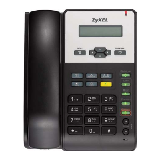
Page 32: Table 2 Front Panel Hardware
Chapter 2 Hardware The following table describes the front panel hardware. Table 2 Front Panel Hardware LABEL DESCRIPTION Handset cradle. LCD (Liquid Crystal Display) screen. Menu Press this to display the V300’s configuration menu. When the menu displays, you can press this key again to exit the menu. The menu is not accessible when a call is in progress. -
Page 33: Figure 5 Side Panel
Chapter 2 Hardware Table 2 Front Panel Hardware (continued) LABEL DESCRIPTION Function keys The LEDs (lights) in these keys illuminate when they are active. VOICEMAIL Use this to check your voicemail messages, once the voicemail number is configured in the V300. MUTE Use this to mute the current call. -
Page 34: Figure 6 Rear Panel
Chapter 2 Hardware Figure 6 Rear Panel The following table describes the rear panel hardware. Table 4 Rear Panel Hardware LABEL DESCRIPTION Power socket Attach the included power adaptor, if you are not using Power over Ethernet (V301 only). See the product specifications appendix for power supply specifications. -
Page 35: The Lcd Screen
Chapter 2 Hardware The following table describes the rear panel hardware. Table 5 Base Panel Hardware LABEL DESCRIPTION Wall-mounting holes Use these to hang the V300 on a wall. See the wall-mounting appendix for details. Handset port Use this to attach the included handset cable’s RJ-11 connector. -
Page 36: Receiving A Call
Chapter 2 Hardware Press the SPEAKER key. • If you want to use a headset: Press the HEADSET key. 2 Check that you can hear a dial tone. 3 Enter the number you want to call. If you have numbers stored in the V300’s phone book, you can use the navigator to select from the list of entries. -
Page 37: Placing A Call On Hold
Chapter 2 Hardware Press the MUTE key once to mute a call. Press it a second time to return to the call. 2.3.6 Placing a Call on Hold When you place a call on hold, you neither receive nor transmit a signal. If your phone system is configured to use the Music on Hold feature, the person on the other end of the line hears the preconfigured music (or other audio). -
Page 38: Transferring A Call
IP PBX to which the V300 is connected to automatically check your phone’s existing firmware and compare it to the firmware on an official ZyXEL server. If your firmware’s version number does not match, the IP PBX will then initiate the upgrade process: 1 When the IP PBX is ready to process your phone, it rings you while the phone is on the hook. -
Page 39: Lcd Screen Menus
LCD Screen Menus Using the LCD Screen (41) The Phonebook (45) LCD Menus: Basic Settings (47) LCD Menus: Advanced (51) -
Page 41: Using The Lcd Screen
H A P T E R Using the LCD Screen 3.1 Overview This chapter shows you how to use and configure the V300 via the LCD screen menu system. See the web configurator section of this guide for background information on the V300’s features. -
Page 42: Enabling And Disabling Features
Chapter 3 Using the LCD Screen 3.3 Enabling and Disabling Features Many of the V300’s LCD screen menus allow you check a feature’s settings and then edit the setting. Take the following steps to check a feature’s current setting and then enable or disable the feature. -
Page 43: Lcd Menu Overview
Chapter 3 Using the LCD Screen The following table shows the numbers, letters and symbols you can enter. Table 6 Keypad Characters MODE Number Uppercase Lowercase Symbol [NONE] [NONE] ! | # A B C a b c : ; “ D E F d e f / \ ? -
Page 44: The Lcd Status Screen
Chapter 3 Using the LCD Screen Table 7 LCD Menu Overview (continued) MENU DESCRIPTION Adv Setting VoIP1 Use this menu to set up the first Voice over Internet (VoIP) account. [Advanced Setting] VoIP2 Use this menu to set up the second Voice over Internet (VoIP) account. -
Page 45: The Phonebook
H A P T E R The Phonebook 4.1 Overview Use the V300’s phonebook to view or store the names and phone numbers of your contacts. The following sections describe how to add and use phonebook entries. The V300 can hold a maximum of 200 private phone numbers and 200 public phone numbers. -
Page 46: Call A Phonebook Contact
Chapter 4 The Phonebook You can view the stored contact entry by pressing the PHONEBOOK key. 4.3 Call a Phonebook Contact In order to call a number you previously entered into the V300’s phonebook, first activate a line (lift the handset, or press the SPEAKER or HEADSET key). The following screen displays. -
Page 47: Lcd Menus: Basic Settings
H A P T E R LCD Menus: Basic Settings 5.1 Overview This chapter discusses how to set up your V300 using the internal configuration menus. 5.1.1 What You Can Do in This Chapter • The Menu system lets you configure your V300 (Section 5.2 on page 47). -
Page 48: The Phonebook Menu
Chapter 5 LCD Menus: Basic Settings 5.3 The Phonebook Menu Use the phonebook to view a list of your contacts. Select MENU > Phonebook. The following screen displays. This is the same fuction as pressing the actual PHONEBOOK button. Figure 16 LCD Menu: Phonebook 1. -
Page 49: The System Info Menu
Chapter 5 LCD Menus: Basic Settings Figure 18 LCD Menu: Volume Screen Speaker Vol:-+ Use the VOLUME keys to increase or decrease the volume. Press to go back to the previous menu when you are done. 5.5 The System Info Menu The System Info menu allows you to quickly check some of your V300’s settings. -
Page 50: The Reset Menu
Chapter 5 LCD Menus: Basic Settings 5.7 The Reset Menu Use this menu to restart the V300 or reset the V300 to the factory defaults. Press MENU > Reset and then to access the Reset menu. The following screen displays. Figure 20 LCD Menu: Reset Menu Setting: 5. -
Page 51: Lcd Menus: Advanced
H A P T E R LCD Menus: Advanced 6.1 Overview This chapter shows you how to use the V300’s LCD menus. 6.1.1 What You Can Do in This Chapter • The VoIP menus let you set up your voice accounts (Section 6.3 on page 52). -
Page 52: The Advanced Setting Menu
Chapter 6 LCD Menus: Advanced HTTPS HyperText Transfer Protocol over Secure Socket Layer, or HTTP over SSL is a web protocol that encrypts and decrypts web pages. Secure Socket Layer (SSL) is an application-level protocol that enables secure transactions of data by ensuring confidentiality (an unauthorized party cannot read the transferred data), authentication (one party can identify the other party) and data integrity (you know if data has been changed). -
Page 53: Sip Active
Chapter 6 LCD Menus: Advanced Figure 26 LCD Menu: Admin Password Entry Password: Press once again after entering the password. If correct, the following screen displays. Figure 27 LCD Menu: SIP Active 1. SIP1/2 Active See the following sections for more information on each menu in this screen. Table 10 LCD Menu: SIP Account Configuration SIP Active Section 6.3.1 on page 53... -
Page 54: Sip Number
Chapter 6 LCD Menus: Advanced 6.3.2 SIP Number Use this to see and edit the SIP number for your SIP account. If you have a SIP account like “1234567@voip-provider.com”, the SIP Number is “1234567”. Select Adv Setting > VoIP1 or VoIP2 > SIP1 Num. The following screen displays. Figure 29 LCD Menu: SIP Number 2. -
Page 55: Sip Server Port
Chapter 6 LCD Menus: Advanced 6.3.3.1 SIP Server Address - Edit Press in the Serv Addr screen. The following screen displays. Figure 32 LCD Menu: SIP Server Address - Edit 3. Serv Addr Use PHONEBOOK to clear the previously-saved settings if any. Enter the new SIP server address and press to save the change. -
Page 56: Sip Register Server
Chapter 6 LCD Menus: Advanced 6.3.5 SIP Register Server Use this menu to see and edit the IP address of the server your SIP service provider uses to register the V300. Select Adv Setting > VoIP1 or VoIP2 > Reg Addr. The following screen displays. -
Page 57: Sip Service Domain
Chapter 6 LCD Menus: Advanced 6.3.6.1 SIP Register Port - Edit Press in the Reg Port screen. The following screen displays. Figure 38 LCD Menu: SIP Register Port - Edit 6. Reg Port 5060_ Use PHONEBOOK to clear the previously-saved settings if any. Enter the new SIP server port number (from 1024 to 65535) and press to save the change. -
Page 58: Sip User Id
Chapter 6 LCD Menus: Advanced 6.3.8 SIP User ID A SIP account’s user ID is its username. Select Adv Setting > VoIP1 or VoIP2 > User ID to see and edit the SIP user name for your SIP account. The following screen displays. Figure 41 LCD Menu: SIP User ID 8. -
Page 59: The Auto Provision Menu
Chapter 6 LCD Menus: Advanced Use PHONEBOOK to clear the previously-saved settings if any. Enter the new SIP authentication password. Press to save the change. Alternatively, press to return to the previous screen. 6.4 The Auto Provision Menu The auto provision menu lets you set up the V300 to receive its configuration data automatically from the SIP server to which it is registered. -
Page 60: Auto Provision Active
Chapter 6 LCD Menus: Advanced 6.4.1 Auto Provision Active When the auto provision feature is set to ON, the V300 then receives all the information it needs to be immediately usable from the SIP server to which it is registered. This is a zero- configuration option that automatically determines the phone’s extension number, IP address, and other relevent network data. -
Page 61: Server Port
Chapter 6 LCD Menus: Advanced If the IP address that you entered is malformed or contains mistakes, then the following error message displays. Figure 50 LCD Menu: Serv Addr Error 3. Serv Addr Invalid IP Addr Otherwise, the IP address that you entered is locked into the phone until manually edited again later. -
Page 62: Dhcp
Chapter 6 LCD Menus: Advanced If you make a mistake, use the PHONEBOOK key to delete your entry one number at a time. Press again to save the retry time. 6.5 DHCP Use DHCP to have the V300 get an IP address automatically from a DHCP server on the network. -
Page 63: Ip Address
Chapter 6 LCD Menus: Advanced Table 13 LCD Menu: Static IP LABEL DESCRIPTION 1st DNS Select this to enter the primary DNS (Domain Name System) server’s IP address. 2nd DNS Select this to enter the secondary (backup) DNS server’s IP address. See the following sections for more information on each menu in this screen. -
Page 64: Subnet Mask
Chapter 6 LCD Menus: Advanced 6.6.2.1 Default Gateway - Edit Press in the Gateway screen. The following screen displays. Figure 59 LCD Menu: Gateway - Edit 3. Gateway 0.0.0.0_ Use PHONEBOOK to clear the previously-saved settings if any. Enter the new gateway IP address and press to save the change. -
Page 65: The Pppoe Menu
Chapter 6 LCD Menus: Advanced 6.6.4.1 First / Second DNS - Edit Press in the 1st DNS or 2nd DNS screen. A screen similar to the following displays (this example uses the 1st DNS screen). Figure 63 LCD Menu: First / Second DNS - Edit 5 1st DNS: 0.0.0.0_ Use PHONEBOOK to clear the previously-saved settings if any. -
Page 66: Pppoe Password
Chapter 6 LCD Menus: Advanced Press to edit the PPPoE username, or press to return to the previous screen. 6.7.1.1 PPPoE Username - Edit If you press in the Username screen, the following screen displays. Figure 66 LCD Menu: PPPoE Username - Edit 2. -
Page 67: Ring Setting
Chapter 6 LCD Menus: Advanced 6.9 Ring Setting Select Adv Setting > Ring Setting. The following screen displays. Figure 70 LCD Menu: Ring Type Ring Type: Chirp 0 Use the keys to cycle through the available ring types. Press to go back to the previous menu when you are done. -
Page 68: Using Flexworker Mode
The Flexworker system lets a person use any V300 connected to an IP PBX that supports auto- provisioning (such as the ZyXEL X6004) and retain its account-specific settings. All available V300 phones are suitable candidates as long as Flexworker is activated in them. -
Page 69: Clock Alarm
Chapter 6 LCD Menus: Advanced 7 Finally, press the key to log out. The following screen displays: FLEXWORKER Logout? Press the key to confirm the logout. 6.12 Clock Alarm Use this menu to view the V300’s three internal clock alarm configurations. Select Advanced Setting >... - Page 70 Chapter 6 LCD Menus: Advanced V300 User’s Guide...
-
Page 71: The Web Configurator
The Web Configurator The Web Configurator (73) The Status Screens (79) Network Setup (85) SIP Account Setup (89) Phone Setup (105) The Phone Book (111) -
Page 73: The Web Configurator
H A P T E R The Web Configurator 7.1 Overview This chapter describes how to access the V300’s web configurator and provides an overview of its screens. 7.2 Accessing the Web Configurator 1 Make sure your hardware is properly connected and prepare your computer or computer network to connect to the V300 (refer to the Quick Start Guide). -
Page 74: Figure 76 Change Password Screen
Chapter 7 The Web Configurator 4 Type “admin” as the default username and "1234" as the password and click Login. Both of these are the device defaults. 5 It is strongly recommended that you change your password in the screen that displays next. -
Page 75: Figure 77 The Status Screen
Chapter 7 The Web Configurator Figure 77 The Status Screen As illustrated above, the web configurator screen is divided into four parts. • A - title bar • B - navigation panel • C - main window • D - status bar V300 User’s Guide... -
Page 76: Title Bar
Chapter 7 The Web Configurator 7.2.1 Title Bar The title bar has some icons in the upper right corner. The icons have the following functions. Table 17 Web Configurator Icons in the Title Bar ICON DESCRIPTION Language: At the time of writing, only English is supported. Help: Click this to see online help related to the current screen. -
Page 77: Main Window
Chapter 7 The Web Configurator Table 18 Navigation Panel Summary LINK FUNCTION Logs View Log Use this screen to display your device’s logs. SIP Message Use this screen to view SIP server messages and responses. Tools Firmware Use this screen to upload firmware to your device. Configuration Use this screen to backup and restore your device’s configuration (settings) or reset the factory default settings. - Page 78 Chapter 7 The Web Configurator V300 User’s Guide...
-
Page 79: The Status Screens
H A P T E R The Status Screens 8.1 Overview Use the Status screens to see the current status of the V300, its system resources, interfaces, and SIP accounts. You can also register and unregister SIP accounts and view detailed traffic and VoIP statistics. -
Page 80: Status Screen
Chapter 8 The Status Screens 8.2 Status Screen This screen displays the overall status and performance statistics of your device. Click Status to display it. Figure 78 Status Screen Each field is described in the following table. Table 19 Status Screen LABEL DESCRIPTION Refresh Interval... - Page 81 Chapter 8 The Status Screens Table 19 Status Screen LABEL DESCRIPTION DHCP This field displays what DHCP services the V300 is receiving from the LAN. Choices are: Client - The V300 is a DHCP client. It is receiving DHCP services. None - The V300 is not receiving DHCP services.
-
Page 82: Packet Statistics
Chapter 8 The Status Screens 8.3 Packet Statistics This screen displays read-only information here includes port status and packet specific statistics. Also provided are "system up time" and "poll interval(s)". The Poll Interval(s) field is configurable. To access it, open the Status screen (see Section 8.2 on page 80), and click (Details...) next to Packet Statistics. -
Page 83: Voip Statistics
Chapter 8 The Status Screens 8.4 VoIP Statistics This screen displays SIP registration information, status of calls and VoIP traffic statistics. To access it, open the Status screen (see Section 8.2 on page 80), and click (Details...) next to VoIP Statistics. Figure 80 VoIP Statistics Each field is described in the following table. - Page 84 Chapter 8 The Status Screens Table 21 VoIP Statistics LABEL DESCRIPTION Last Outgoing This field displays the last number the SIP account called. It displays N/A if the Number SIP account has never dialed a number. Call Statistics Call This field displays the V300’s line number. Peer Number This field displays the SIP number of the person on the other end of the line, when a call is in progress.
-
Page 85: Network Setup
H A P T E R Network Setup 9.1 Overview This chapter discusses how to configure the V300’s network settings. 9.1.1 What You Can Do in This Chapter • The Internet Connection screen lets you change your V300’s Internet access settings (Section 9.2 on page 87). - Page 86 Chapter 9 Network Setup Regardless of your particular situation, do not create an arbitrary IP address; always follow the guidelines above. For more information on address assignment, please refer to RFC 1597, Address Allocation for Private Internets and RFC 1466, Guidelines for Management of IP Address Space. IP Address and Subnet Mask Similar to the way houses on a street share a common street name, computers on a LAN share one common network number.
-
Page 87: Internet Connection
Chapter 9 Network Setup 9.2 Internet Connection Use this screen to change your V300’s Internet access settings. Click Network > Internet Connection. Figure 81 Network > Internet Connection The following table describes the labels in this screen. Table 23 Network > Internet Connection LABEL DESCRIPTION Ethernet TCP/IP Settings... -
Page 88: Management Port
Chapter 9 Network Setup 9.3 Management Port Use this screen to configure the management IP address of the V300. You can use this IP address to connect to the V300 even when its WAN IP address is in a different subnet. Your computer must be in the same subnet as the management IP address to use it. -
Page 89: Sip Account Setup
H A P T E R SIP Account Setup 10.1 Overview This chapter discusses the V300’s VoIP > SIP screens. 10.1.1 What You Can Do in This Chapter • The SIP Settings screen lets you maintain basic information about each SIP account (Section 10.2 on page 96). -
Page 90: Table 25 Sip Call Progression
Chapter 10 SIP Account Setup SIP Identities A SIP account uses an identity (sometimes referred to as a SIP address). A complete SIP identity is called a SIP URI (Uniform Resource Identifier). A SIP account's URI identifies the SIP account in a way similar to the way an e-mail address identifies an e-mail account. The format of a SIP identity is SIP-Number@SIP-Service-Domain. -
Page 91: Figure 83 Sip User Agent
Chapter 10 SIP Account Setup When you use SIP to make a VoIP call, it originates at a client and terminates at a server. A SIP client could be a computer or a SIP phone. One device can act as both a SIP client and a SIP server. -
Page 92: Figure 85 Sip Redirect Server
Chapter 10 SIP Account Setup SIP Redirect Server A SIP redirect server accepts SIP requests, translates the destination address to an IP address and sends the translated IP address back to the device that sent the request. Then the client device that originally sent the request can send requests to the IP address that it received back from the redirect server. -
Page 93: Figure 86 Stun
Chapter 10 SIP Account Setup The V300 must register its public IP address with a SIP register server. If there is a NAT router between the V300 and the SIP register server, the V300 probably has a private IP address. The V300 lists its IP address in the SIP message that it sends to the SIP register server. - Page 94 Chapter 10 SIP Account Setup • G.711 is a Pulse Code Modulation (PCM) waveform codec. PCM measures analog signal amplitudes at regular time intervals (sampling) and converts them into digital bits (quantization). Quantization “reads” the analog signal and then “writes” it to the nearest digital value.
-
Page 95: Figure 87 Diffserv: Differentiated Service Field
Chapter 10 SIP Account Setup Type Of Service (ToS) Network traffic can be classified by setting the ToS (Type Of Service) values at the data source (for example, at the V300) so a server can decide the best method of delivery, that is the least cost, fastest route and so on. -
Page 96: The Sip Settings Screen
Chapter 10 SIP Account Setup 10.2 The SIP Settings Screen Use this screen to maintain basic information about each SIP account. Your VoIP service provider (the company that lets you make phone calls over the Internet) should provide this. You can also enable and disable each SIP account. To access this screen, click VoIP > SIP > SIP Settings. -
Page 97: Table 26 Voip > Sip > Sip Settings
Chapter 10 SIP Account Setup Each field is described in the following table. Table 26 VoIP > SIP > SIP Settings LABEL DESCRIPTION SIP Settings SIP Account Select the SIP account you want to see in this screen. At the time of writing, the V300 supports two SIP accounts. - Page 98 Chapter 10 SIP Account Setup Table 26 VoIP > SIP > SIP Settings LABEL DESCRIPTION Register Enter the backup SIP register server’s listening port number, if your VoIP service Service Port provider gave you one. Otherwise, enter the same port number you entered in the SIP Service Port field for this backup server.
-
Page 99: Advanced Sip Setup Screen
Chapter 10 SIP Account Setup 10.2.1 Advanced SIP Setup Screen Use this screen to maintain advanced settings for each SIP account. Click Advanced Setup in VoIP > SIP > SIP Settings. The following screen displays. Figure 89 VoIP > SIP > SIP Settings > Advanced V300 User’s Guide... -
Page 100: Table 27 Voip > Sip > Sip Settings > Advanced Setup
Chapter 10 SIP Account Setup Each field is described in the following table. Table 27 VoIP > SIP > SIP Settings > Advanced Setup LABEL DESCRIPTION SIP Server Settings URL Type Select whether or not to include the SIP service domain name when the V300 sends the SIP number. - Page 101 Chapter 10 SIP Account Setup Table 27 VoIP > SIP > SIP Settings > Advanced Setup (continued) LABEL DESCRIPTION DTMF Mode Control how the V300 handles the alphanumeric keypad tones. You should use the same mode your VoIP service provider uses. RFC 2833 - send the DTMF tones in RTP packets PCM - send the DTMF tones in the voice data stream.
- Page 102 Chapter 10 SIP Account Setup Table 27 VoIP > SIP > SIP Settings > Advanced Setup (continued) LABEL DESCRIPTION Expiration Keep the default value, unless your VoIP service provider tells you to change it. Time Enter the number of seconds the SIP server should provide the message waiting service each time the V300 subscribes to the service.
-
Page 103: Sip Qos Screen
Chapter 10 SIP Account Setup 10.3 SIP QoS Screen Use this screen to maintain ToS and VLAN settings for the V300. Click VoIP > SIP > QoS. The following screen displays. Figure 90 VoIP > SIP > QoS Each field is described in the following table. Table 28 VoIP >... - Page 104 Chapter 10 SIP Account Setup V300 User’s Guide...
-
Page 105: Phone Setup
H A P T E R Phone Setup 11.1 Overview This chapter discusses the V300’s Phone screens. 11.2 What You Can Do in This Chapter • The Phone Settings screen lets you adjust the V300’s volume levels (Section 11.3 on page 106). -
Page 106: Phone Settings Screen
Chapter 11 Phone Setup 11.3 Phone Settings Screen Use this screen to configure basic phone settings like volume levels. Click VoIP > Phone > Phone Settings. The following screen displays. Figure 91 VoIP > Phone > Phone Settings V300 User’s Guide... -
Page 107: Table 29 Voip > Phone > Phone Settings
Chapter 11 Phone Setup Each field is described in the following table. Table 29 VoIP > Phone > Phone Settings LABEL DESCRIPTION Volume Control Ring Volume Select this to set the volume of the V300’s ringtone. 0 is the quietest and 12 is the loudest. Speaker Rx Select this to set the internal speakerphone’s inbound volume. -
Page 108: Voice Activity Detection/Silence Suppression
Chapter 11 Phone Setup Table 29 VoIP > Phone > Phone Settings LABEL DESCRIPTION Speaker Mode Select either Speaker or Headset as the preferred method for picking up pages. / Headset Mode Flexworker Mode Enable Select this to enable the Flexworker feature, which allows other people in the Flexworker company to use this device in conjunction with their personal account settings. -
Page 109: Speed Dial Settings Screen
Chapter 11 Phone Setup Each field is described in the following table. Table 30 VoIP > Phone > Region LABEL DESCRIPTION Region Setting Region Select the place in which the V300 is located. Settings Apply Click this to save your changes. Reset Click this to set this screen to its last-saved value. -
Page 110: Programmable Feature Key Settings Screen
Chapter 11 Phone Setup Each field is described in the following table. Table 31 Phone Book > Speed Dial LABEL DESCRIPTION Speed Dial Settings Speed Dial Key 1 Enter the SIP URI (peer-to-peer call) that you want the V300 to call when you use this speed dial key. -
Page 111: The Phone Book
H A P T E R The Phone Book 12.1 Overview This chapter discusses the Phone Book screens. The V300 can hold a maximum of 200 private phone numbers and 200 public phone numbers. Public phone numbers are provided by the PBX to which your phone is connected, while private numbers are the ones you enter into your phone memory yourself. -
Page 112: Call Forward Screen
Chapter 12 The Phone Book 12.2 Call Forward Screen Use this screen to configure call forwarding for incoming calls. When call forwarding is active, incoming calls are redirected to other phone numbers. You can set up rules for all incoming calls, or have the V300 forward calls from specific numbers only. Click VoIP >... - Page 113 Chapter 12 The Phone Book Table 33 VoIP > Phone Book > Call Forward (continued) LABEL DESCRIPTION Busy Forward Select this if you want the V300 to forward incoming calls to the specified phone to Number number if the phone is busy (it does not matter which line is being used). Specify the phone number in the field on the right.
-
Page 114: Contact List Screen
Chapter 12 The Phone Book Table 33 VoIP > Phone Book > Call Forward (continued) LABEL DESCRIPTION Apply Click this to save your settings. Reset Click this to set every field in this screen to its last-saved value. 12.3 Contact List Screen Use this screen to see, add and edit details of your contacts. -
Page 115: Group List Screen
Chapter 12 The Phone Book Table 34 VoIP > Phone Book > Contact List (continued) LABEL DESCRIPTION Item This shows the index number of the contact’s entry. Number This is the contact’s phone number. Name This is the contact’s name. Group This is the calling group to which the contact belongs. -
Page 116: Figure 97 Voip > Phone Book > Group List
Chapter 12 The Phone Book Figure 97 VoIP > Phone Book > Group List The following table describes the labels in this screen. Table 35 VoIP > Phone Book > Group List LABEL DESCRIPTION Group List Group Select the calling group you want to see. The list of group members displays in the Group List Table. -
Page 117: Block List Screen
Chapter 12 The Phone Book 12.5 Block List Screen Use this screen to see and edit details of the phone numbers that are prevented from making incoming calls to the V300. Click VoIP > Phone Book > Block List. The following screen displays. Figure 98 VoIP >... -
Page 118: Dnd White List Screen
Chapter 12 The Phone Book Table 36 VoIP > Phone Book > Block List (continued) LABEL DESCRIPTION Modify Click the Edit icon to change this entry’s details. Click the Delete icon to remove the entry from the block list. If you do this for an entry not in the phonebook, the information cannot be recovered. -
Page 119: Table 37 Voip > Phone Book > Dnd White List
Chapter 12 The Phone Book The following table describes the labels in this screen. Table 37 VoIP > Phone Book > DND White List LABEL DESCRIPTION DND White LIst Item This is the index number of the DND white list entry. Number Enter the phone number you want to add to the list. - Page 120 Chapter 12 The Phone Book V300 User’s Guide...
-
Page 121: Maintenance And Troubleshooting
Maintenance and Troubleshooting System (123) Logs (131) Tools (133) Troubleshooting (141) -
Page 123: System
H A P T E R System 13.1 Overview Use the System screens to change the V300’s system and domain name settings, change the password or configure time settings. 13.2 What You Can Do in This Chapter • The General screen lets you change system settings and the web configurator password, or to set the administrator inactivity timer (Section 13.3 on page 124). -
Page 124: General Screen
Chapter 13 System 13.3 General Screen Use this screen to change system settings and the web configurator password, or to set the administrator inactivity timer. If you forget your password you will need to reset the device. See your Quick Start Guide for details. - Page 125 Chapter 13 System Table 38 Maintenance > System > General (continued) LABEL DESCRIPTION Administrator Type how many seconds a management session can be left idle before the Inactivity session times out. After it times out you have to log in with your password again. Timer Very long idle timeouts may have security risks.
-
Page 126: Time Setting Screen
Chapter 13 System 13.4 Time Setting Screen To change your V300’s time and date, click Maintenance > System > Time Setting. The screen appears as shown. Use this screen to configure the V300’s time based on your local time zone. Figure 101 Maintenance >... - Page 127 Chapter 13 System Table 39 Maintenance > Time Setting (continued) LABEL DESCRIPTION New Date This field displays the last updated date from the time server or the last date (yyyy/mm/dd) configured manually. When you set Time and Date Setup to Manual, enter the new date in this field and then click Apply.
-
Page 128: Dynamic Dns
Chapter 13 System 13.5 Dynamic DNS Dynamic DNS allows you to map your current dynamic IP address with one or many dynamic DNS services so that anyone can contact you. SIP IP phones can access the SIP server on the V300 using a domain name (for instance myhost.dhs.org, where myhost is a name of your choice) that will never change instead of using an IP address that changes each time you reconnect. -
Page 129: Clock Alarm Setting
Chapter 13 System 13.6 Clock Alarm Setting Click Maintenance > System > Clock Alarm Setting. The screen appears as shown. Use this screen to configure the V300’s clock alarm schedule. The three alarms must have different configurations. You cannot have two or three identical alarms. - Page 130 Chapter 13 System V300 User’s Guide...
-
Page 131: Logs
H A P T E R Logs 14.1 Overview This chapter contains information on viewing your V300’s logs. 14.2 Logs Screen Click Maintenance > Logs to open the Logs screen. You can view logs and alert messages in this screen. Once the log table is full, old logs are deleted as new logs are created. -
Page 132: Sip Message
Chapter 14 Logs Table 42 Maintenance > Logs (continued) LABEL DESCRIPTION Destination This field lists the destination IP address and the port number of the outgoing packet that caused the log, if applicable. Note This field displays additional information about the log entry. 14.3 SIP Message Click Maintenance >... -
Page 133: Tools
139). 15.2 Firmware Screen Find firmware at www.zyxel.com in a file that (usually) uses the system model name with a "*.bin" extension, e.g., "V300.bin". The upload process uses HTTP (Hypertext Transfer Protocol) and may take up to two minutes. After a successful upload, the system will reboot. -
Page 134: Figure 107 Upload Warning
Chapter 15 Tools The following table describes the labels in this screen. Table 44 Maintenance > Tools > Firmware Upload LABEL DESCRIPTION Firmware Upgrade File Upload Type in the location of the file you want to upload in this field or click Browse... to find Browse... -
Page 135: Configuration Screen
Chapter 15 Tools Figure 109 Upload Error Message 15.3 Configuration Screen Click Maintenance > Tools > Configuration. Information related to factory defaults, backup configuration, and restoring configuration appears on this screen. Figure 110 Maintenance > Tools > Configuration 15.3.1 Backup Configuration Backup configuration allows you to back up (save) the V300’s current configuration to a file on your computer. -
Page 136: Restore Configuration
Chapter 15 Tools 15.3.2 Restore Configuration Restore configuration allows you to upload a new or previously saved configuration file from your computer to your V300. Table 45 Maintenance > Tools > Configuration > Restore LABEL DESCRIPTION Restore Configuration File Path Type in the location of the file you want to upload in this field or click Browse... -
Page 137: Save Debug Log
Chapter 15 Tools Figure 113 Configuration Restore Error 15.3.3 Save Debug Log Save Debug Log allows you save a copy of the V300’s debug log to your computer. This is useful if you encounter any problems with the device and need to talk to customer support. 15.3.4 Back to Factory Defaults Back to Factory Defaults let you clear all user-entered configuration information and returns the V300 to its factory defaults. -
Page 138: Ring Maintenance Screen
Chapter 15 Tools 15.5 Ring Maintenance Screen This screen allows you to upload files to the V300 and use them as ringtones. These files must be MIDI (Musical Instrument Digital Interface) files with a “.midi” extension. You can also download files from the V300 to your computer. The V300 has ten MIDI file slots. -
Page 139: Packet Mirror Screen
Chapter 15 Tools Table 46 Maintenance > Tools > Ring Maintenance LABEL DESCRIPTION Ring Download Download Click this to download the MIDI file you selected in the Ring Midi File Select list to your computer. The file is saved in .rar format. 15.6 Packet Mirror Screen This screen is where you can configure packet mirroring on the V300. -
Page 140: Table 47 Maintenance > Tools > Ring Maintenance
Chapter 15 Tools The following table describes the labels in this screen. Table 47 Maintenance > Tools > Ring Maintenance LABEL DESCRIPTION Active Check this to enable packet mirroring. Mirror IP Enter an IP address to which mirrored packets are sent. The mirror IP and the V300’s IP must be in the same subnet. -
Page 141: Troubleshooting
H A P T E R Troubleshooting 16.1 Overview This chapter offers some suggestions to solve problems you might encounter. The potential problems are divided into the following categories. • Power, Hardware Connections, and LEDs • Internet Access • Phone Calls and VoIP 16.2 Power, Hardware Connections, and LEDs The V300 does not turn on. - Page 142 Chapter 16 Troubleshooting I forgot the IP address for the V300. 1 The V300 is set to get an IP address automatically by default. Check the IP address in the System Info > IP Address > IP Address LCD menu. 2 Set a static IP address for the V300 in the Adv Setting >...
-
Page 143: Internet Access
Chapter 16 Troubleshooting I can see the Login screen, but I cannot log in to the V300. 1 Make sure you have entered the user name and password correctly. The default password is 1234. This field is case-sensitive, so make sure [Caps Lock] is not on. 2 You cannot log in to the web configurator while someone is using Telnet to access the V300. -
Page 144: Phone Calls And Voip
Chapter 16 Troubleshooting I cannot access the Internet anymore. I had access to the Internet (with the V300), but my Internet connection is not available anymore. 1 Check the hardware connections, and make sure the LEDs and the LCD screen are behaving as expected. - Page 145 Chapter 16 Troubleshooting • If you use a static IP address, see Section 6.6 on page 62 for how to change DNS settings. • If you use a dynamic IP address (DHCP) your DNS settings are controlled by the DHCP server. The DHCP server may belong to your service provider, or it may be on your network.
- Page 146 Chapter 16 Troubleshooting I cannot use some calling features. Many of the features your V300 supports depend on your VoIP service provider. You may have to subscribe to certain services. Contact your VoIP service provider for more information. The incoming or outgoing audio is too quiet or too loud. I cannot hear the V300’s ring when a call is incoming.
-
Page 147: Appendices And Index
Appendices and Index Product Specifications (149) Setting Up Your Computer’s IP Address (155) Pop-up Windows, JavaScripts and Java Permissions (179) IP Addresses and Subnetting (185) Legal Information (193) Customer Support (203) Index (209) -
Page 149: Appendix A Product Specifications
P P E N D I X Product Specifications The following tables summarize the V300’s hardware and firmware features. Table 48 Hardware Specifications Dimensions (W x D x H) 16.5mm x 208mm x 91.5mm Weight 465g Power Specification 12V DC, 1.5A Power over Ethernet IEEE 802.3af compliant. -
Page 150: Table 49 Firmware Specifications
Firmware Upgrade Download new firmware (when available) from the ZyXEL web site and use the web configurator, an FTP or a TFTP tool to put it on the V300. Note: Only upload firmware for your specific model! Configuration Backup &... -
Page 151: Table 50 Standards Supported
Appendix A Product Specifications The following list, which is not exhaustive, illustrates the standards supported in the V300. Table 50 Standards Supported STANDARD DESCRIPTION RFC 1058 RIP-1 (Routing Information Protocol) RFC 1112 IGMP v1 RFC 1305 Network Time Protocol (NTP version 3) RFC 1321 The MD5 Message-Digest Algorithm RFC 1483... -
Page 152: Figure 118 Wall-Mounting Example
Appendix A Product Specifications Wall-mounting Instructions Complete the following steps to hang your V300 on a wall. Table 48 on page 149 for the size of screws to use and how far apart to place them. 1 Select a position free of obstructions on a sturdy wall. 2 Drill two holes for the screws. -
Page 153: Figure 119 Masonry Plug And M4 Tap Screw
Appendix A Product Specifications Figure 119 Masonry Plug and M4 Tap Screw V300 User’s Guide... - Page 154 Appendix A Product Specifications V300 User’s Guide...
-
Page 155: Appendix B Setting Up Your Computer's Ip Address
P P E N D I X Setting Up Your Computer’s IP Address Your specific ZyXEL device may not support all of the operating systems described in this appendix. See the product specifications for more information about which operating systems are supported. -
Page 156: Figure 120 Windows Xp: Start Menu
Appendix B Setting Up Your Computer’s IP Address Windows XP/NT/2000 The following example uses the default Windows XP display theme but can also apply to Windows 2000 and Windows NT. 1 Click Start > Control Panel. Figure 120 Windows XP: Start Menu 2 In the Control Panel, click the Network Connections icon. -
Page 157: Figure 122 Windows Xp: Control Panel > Network Connections > Properties
Appendix B Setting Up Your Computer’s IP Address 3 Right-click Local Area Connection and then select Properties. Figure 122 Windows XP: Control Panel > Network Connections > Properties 4 On the General tab, select Internet Protocol (TCP/IP) and then click Properties. Figure 123 Windows XP: Local Area Connection Properties NWD271N User’s Guide... -
Page 158: Figure 124 Windows Xp: Internet Protocol (Tcp/Ip) Properties
Appendix B Setting Up Your Computer’s IP Address 5 The Internet Protocol TCP/IP Properties window opens. Figure 124 Windows XP: Internet Protocol (TCP/IP) Properties 6 Select Obtain an IP address automatically if your network administrator or ISP assigns your IP address dynamically. Select Use the following IP Address and fill in the IP address, Subnet mask, and Default gateway fields if you have a static IP address that was assigned to you by your network administrator or ISP. -
Page 159: Figure 125 Windows Vista: Start Menu
Appendix B Setting Up Your Computer’s IP Address Windows Vista This section shows screens from Windows Vista Professional. 1 Click Start > Control Panel. Figure 125 Windows Vista: Start Menu 2 In the Control Panel, click the Network and Internet icon. Figure 126 Windows Vista: Control Panel 3 Click the Network and Sharing Center icon. -
Page 160: Figure 128 Windows Vista: Network And Sharing Center
Appendix B Setting Up Your Computer’s IP Address 4 Click Manage network connections. Figure 128 Windows Vista: Network and Sharing Center 5 Right-click Local Area Connection and then select Properties. Figure 129 Windows Vista: Network and Sharing Center During this procedure, click Continue whenever Windows displays a screen saying that it needs your permission to continue. -
Page 161: Figure 130 Windows Vista: Local Area Connection Properties
Appendix B Setting Up Your Computer’s IP Address 6 Select Internet Protocol Version 4 (TCP/IPv4) and then select Properties. Figure 130 Windows Vista: Local Area Connection Properties NWD271N User’s Guide... -
Page 162: Figure 131 Windows Vista: Internet Protocol Version 4 (Tcp/Ipv4) Properties
Appendix B Setting Up Your Computer’s IP Address 7 The Internet Protocol Version 4 (TCP/IPv4) Properties window opens. Figure 131 Windows Vista: Internet Protocol Version 4 (TCP/IPv4) Properties 8 Select Obtain an IP address automatically if your network administrator or ISP assigns your IP address dynamically. -
Page 163: Figure 132 Mac Os X 10.4: Apple Menu
Appendix B Setting Up Your Computer’s IP Address Mac OS X: 10.3 and 10.4 The screens in this section are from Mac OS X 10.4 but can also apply to 10.3. 1 Click Apple > System Preferences. Figure 132 Mac OS X 10.4: Apple Menu 2 In the System Preferences window, click the Network icon. -
Page 164: Figure 134 Mac Os X 10.4: Network Preferences
Appendix B Setting Up Your Computer’s IP Address 3 When the Network preferences pane opens, select Built-in Ethernet from the network connection type list, and then click Configure. Figure 134 Mac OS X 10.4: Network Preferences 4 For dynamically assigned settings, select Using DHCP from the Configure IPv4 list in the TCP/IP tab. -
Page 165: Figure 136 Mac Os X 10.4: Network Preferences > Ethernet
Appendix B Setting Up Your Computer’s IP Address 5 For statically assigned settings, do the following: • From the Configure IPv4 list, select Manually. • In the IP Address field, type your IP address. • In the Subnet Mask field, type your subnet mask. •... -
Page 166: Figure 138 Mac Os X 10.5: Apple Menu
Appendix B Setting Up Your Computer’s IP Address Mac OS X: 10.5 The screens in this section are from Mac OS X 10.5. 1 Click Apple > System Preferences. Figure 138 Mac OS X 10.5: Apple Menu 2 In System Preferences, click the Network icon. Figure 139 Mac OS X 10.5: Systems Preferences NWD271N User’s Guide... -
Page 167: Figure 140 Mac Os X 10.5: Network Preferences > Ethernet
Appendix B Setting Up Your Computer’s IP Address 3 When the Network preferences pane opens, select Ethernet from the list of available connection types. Figure 140 Mac OS X 10.5: Network Preferences > Ethernet 4 From the Configure list, select Using DHCP for dynamically assigned settings. 5 For statically assigned settings, do the following: •... -
Page 168: Figure 141 Mac Os X 10.5: Network Preferences > Ethernet
Appendix B Setting Up Your Computer’s IP Address Figure 141 Mac OS X 10.5: Network Preferences > Ethernet 6 Click Apply and close the window. Verifying Settings Check your TCP/IP properties by clicking Applications > Utilities > Network Utilities, and then selecting the appropriate Network interface from the Info tab. -
Page 169: Figure 143 Ubuntu 8: System > Administration Menu
Appendix B Setting Up Your Computer’s IP Address Linux: Ubuntu 8 (GNOME) This section shows you how to configure your computer’s TCP/IP settings in the GNU Object Model Environment (GNOME) using the Ubuntu 8 Linux distribution. The procedure, screens and file locations may vary depending on your specific distribution, release version, and individual configuration. -
Page 170: Figure 145 Ubuntu 8: Administrator Account Authentication
Appendix B Setting Up Your Computer’s IP Address 3 In the Authenticate window, enter your admin account name and password then click the Authenticate button. Figure 145 Ubuntu 8: Administrator Account Authentication 4 In the Network Settings window, select the connection that you want to configure, then click Properties. -
Page 171: Figure 147 Ubuntu 8: Network Settings > Properties
Appendix B Setting Up Your Computer’s IP Address 5 The Properties dialog box opens. Figure 147 Ubuntu 8: Network Settings > Properties • In the Configuration list, select Automatic Configuration (DHCP) if you have a dynamic IP address. • In the Configuration list, select Static IP address if you have a static IP address. Fill in the IP address, Subnet mask, and Gateway address fields. -
Page 172: Figure 149 Ubuntu 8: Network Tools
Appendix B Setting Up Your Computer’s IP Address Verifying Settings Check your TCP/IP properties by clicking System > Administration > Network Tools, and then selecting the appropriate Network device from the Devices tab. The Interface Statistics column shows data if your connection is working properly. Figure 149 Ubuntu 8: Network Tools NWD271N User’s Guide... -
Page 173: Figure 150 Opensuse 10.3: K Menu > Computer Menu
Appendix B Setting Up Your Computer’s IP Address Linux: openSUSE 10.3 (KDE) This section shows you how to configure your computer’s TCP/IP settings in the K Desktop Environment (KDE) using the openSUSE 10.3 Linux distribution. The procedure, screens and file locations may vary depending on your specific distribution, release version, and individual configuration. -
Page 174: Figure 152 Opensuse 10.3: Yast Control Center
Appendix B Setting Up Your Computer’s IP Address 3 When the YaST Control Center window opens, select Network Devices and then click the Network Card icon. Figure 152 openSUSE 10.3: YaST Control Center 4 When the Network Settings window opens, click the Overview tab, select the appropriate connection Name from the list, and then click the Configure button. -
Page 175: Figure 154 Opensuse 10.3: Network Card Setup
Appendix B Setting Up Your Computer’s IP Address 5 When the Network Card Setup window opens, click the Address tab Figure 154 openSUSE 10.3: Network Card Setup 6 Select Dynamic Address (DHCP) if you have a dynamic IP address. Select Statically assigned IP Address if you have a static IP address. Fill in the IP address, Subnet mask, and Hostname fields. -
Page 176: Figure 155 Opensuse 10.3: Network Settings
Appendix B Setting Up Your Computer’s IP Address 8 If you know your DNS server IP address(es), click the Hostname/DNS tab in Network Settings and then enter the DNS server information in the fields provided. Figure 155 openSUSE 10.3: Network Settings 9 Click Finish to save your settings and close the window. -
Page 177: Figure 156 Opensuse 10.3: Knetwork Manager
Appendix B Setting Up Your Computer’s IP Address Verifying Settings Click the KNetwork Manager icon on the Task bar to check your TCP/IP properties. From the Options sub-menu, select Show Connection Information. Figure 156 openSUSE 10.3: KNetwork Manager When the Connection Status - KNetwork Manager window opens, click the Statistics tab to see if your connection is working properly. - Page 178 Appendix B Setting Up Your Computer’s IP Address NWD271N User’s Guide...
-
Page 179: Appendix C Pop-Up Windows, Javascripts And Java Permissions
P P E N D I X Pop-up Windows, JavaScripts and Java Permissions In order to use the web configurator you need to allow: • Web browser pop-up windows from your device. • JavaScripts (enabled by default). • Java permissions (enabled by default). Internet Explorer 6 screens are used here. -
Page 180: Figure 159 Internet Options: Privacy
Appendix C Pop-up Windows, JavaScripts and Java Permissions 2 Clear the Block pop-ups check box in the Pop-up Blocker section of the screen. This disables any web pop-up blockers you may have enabled. Figure 159 Internet Options: Privacy 3 Click Apply to save this setting. Enable pop-up Blockers with Exceptions Alternatively, if you only want to allow pop-up windows from your device, see the following steps. -
Page 181: Figure 160 Internet Options: Privacy
Appendix C Pop-up Windows, JavaScripts and Java Permissions Figure 160 Internet Options: Privacy 3 Type the IP address of your device (the web page that you do not want to have blocked) with the prefix “http://”. For example, http://192.168.167.1. 4 Click Add to move the IP address to the list of Allowed sites. Figure 161 Pop-up Blocker Settings V300 User’s Guide... -
Page 182: Figure 162 Internet Options: Security
Appendix C Pop-up Windows, JavaScripts and Java Permissions 5 Click Close to return to the Privacy screen. 6 Click Apply to save this setting. JavaScripts If pages of the web configurator do not display properly in Internet Explorer, check that JavaScripts are allowed. -
Page 183: Figure 163 Security Settings - Java Scripting
Appendix C Pop-up Windows, JavaScripts and Java Permissions Figure 163 Security Settings - Java Scripting Java Permissions 1 From Internet Explorer, click Tools, Internet Options and then the Security tab. 2 Click the Custom Level... button. 3 Scroll down to Microsoft VM. 4 Under Java permissions make sure that a safety level is selected. -
Page 184: Figure 165 Java (Sun)
Appendix C Pop-up Windows, JavaScripts and Java Permissions JAVA (Sun) 1 From Internet Explorer, click Tools, Internet Options and then the Advanced tab. 2 Make sure that Use Java 2 for <applet> under Java (Sun) is selected. 3 Click OK to close the window. Figure 165 Java (Sun) V300 User’s Guide... -
Page 185: Appendix D Ip Addresses And Subnetting
P P E N D I X IP Addresses and Subnetting This appendix introduces IP addresses and subnet masks. IP addresses identify individual devices on a network. Every networking device (including computers, servers, routers, printers, etc.) needs an IP address to communicate across the network. -
Page 186: Figure 166 Network Number And Host Id
Appendix D IP Addresses and Subnetting Figure 166 Network Number and Host ID How much of the IP address is the network number and how much is the host ID varies according to the subnet mask. Subnet Masks A subnet mask is used to determine which bits are part of the network number, and which bits are part of the host ID (using a logical AND operation). -
Page 187: Table 52 Subnet Masks
Appendix D IP Addresses and Subnetting Subnet masks are expressed in dotted decimal notation just like IP addresses. The following examples show the binary and decimal notation for 8-bit, 16-bit, 24-bit and 29-bit subnet masks. Table 52 Subnet Masks BINARY DECIMAL 4TH OCTET OCTET... -
Page 188: Figure 167 Subnetting Example: Before Subnetting
Appendix D IP Addresses and Subnetting Table 54 Alternative Subnet Mask Notation (continued) ALTERNATIVE LAST OCTET LAST OCTET SUBNET MASK NOTATION (BINARY) (DECIMAL) 255.255.255.192 1100 0000 255.255.255.224 1110 0000 255.255.255.240 1111 0000 255.255.255.248 1111 1000 255.255.255.252 1111 1100 Subnetting You can use subnetting to divide one network into multiple sub-networks. In the following example a network administrator creates two sub-networks to isolate a group of servers from the rest of the company network for security reasons. -
Page 189: Table 55 Subnet 1
Appendix D IP Addresses and Subnetting Figure 168 Subnetting Example: After Subnetting In a 25-bit subnet the host ID has 7 bits, so each sub-network has a maximum of 2 – 2 or 126 possible hosts (a host ID of all zeroes is the subnet’s address itself, all ones is the subnet’s broadcast address). -
Page 190: Table 56 Subnet 2
Appendix D IP Addresses and Subnetting Table 56 Subnet 2 LAST OCTET BIT IP/SUBNET MASK NETWORK NUMBER VALUE IP Address 192.168.1. IP Address (Binary) 11000000.10101000.00000001. 01000000 Subnet Mask (Binary) 11111111.11111111.11111111. 11000000 Subnet Address: Lowest Host ID: 192.168.1.65 192.168.1.64 Broadcast Address: Highest Host ID: 192.168.1.126 192.168.1.127 Table 57 Subnet 3... -
Page 191: Table 60 24-Bit Network Number Subnet Planning
Appendix D IP Addresses and Subnetting Table 59 Eight Subnets (continued) SUBNET LAST BROADCAST SUBNET FIRST ADDRESS ADDRESS ADDRESS ADDRESS Subnet Planning The following table is a summary for subnet planning on a network with a 24-bit network number. Table 60 24-bit Network Number Subnet Planning NO. - Page 192 Appendix D IP Addresses and Subnetting Table 61 16-bit Network Number Subnet Planning (continued) NO. “BORROWED” NO. HOSTS PER SUBNET MASK NO. SUBNETS HOST BITS SUBNET 255.255.255.252 (/30) 16384 255.255.255.254 (/31) 32768 Configuring IP Addresses Where you obtain your network number depends on your particular situation. If the ISP or your network administrator assigns you a block of registered IP addresses, follow their instructions in selecting the IP addresses and the subnet mask.
-
Page 193: Appendix E Legal Information
Published by ZyXEL Communications Corporation. All rights reserved. Disclaimer ZyXEL does not assume any liability arising out of the application or use of any products, or software described herein. Neither does it convey any license under its patent rights nor the patent rights of others. - Page 194 Any replacement will consist of a new or re-manufactured functionally equivalent product of equal or higher value, and will be solely at the discretion of ZyXEL. This warranty shall not apply if the product has been modified, misused, tampered with, damaged by an act of God, or subjected to abnormal working conditions.
- Page 195 Appendix E Legal Information ZyXEL) and the customer will be billed for parts and labor. All repaired or replaced products will be shipped by ZyXEL to the corresponding return address, Postage Paid. This warranty gives you specific legal rights, and you may also have other rights that vary from country to country.
- Page 196 Appendix E Legal Information V300 User’s Guide...
-
Page 197: Appendix F Open Software Announcements
Software as long as this License Agreement remains in full force and effect. Ownership of the Software, Documentation and all intellectual property rights therein shall remain at all times with ZyXEL. Any other use of the Software by any other entity is strictly forbidden and is a violation of this License Agreement. - Page 198 International Copyright Law and trade secret law, and by international treaty provisions. All rights not granted to you herein are expressly reserved by ZyXEL. You may not remove any proprietary notice of ZyXEL or any of its licensors from any copy of the Software or Documentation.
- Page 199 SOFTWARE, AND NO WARRANTIES SHALL APPLY AFTER THAT PERIOD. Limitation of Liability IN NO EVENT WILL ZyXEL BE LIABLE TO YOU OR ANY THIRD PARTY FOR ANY INCIDENTAL OR CONSEQUENTIAL DAMAGES (INCLUDING, WITHOUT LIMITATION, INDIRECT, SPECIAL, PUNITIVE, OR EXEMPLARY DAMAGES FOR...
- Page 200 Software and Documentation in your possession or under your control. ZyXEL may terminate this License Agreement for any reason, including, but not limited to, if ZyXEL finds that you have violated any of the terms of this License Agreement. Upon notification of termination, you agree to destroy or return to ZyXEL all copies of the Software and Documentation and to certify in writing that all known copies, including backup copies, have been destroyed.
-
Page 201: Table 62 Open Source Components
Note: NOTE: Some components of this product incorporate source code covered under the open source code licenses. To obtain the source code covered under those Licenses, please check ZyXEL Technical Support (support@zyxel.com.tw) to get it. Table 62 Open Source Components... - Page 202 Appendix F Open Software Announcements V300 User’s Guide...
-
Page 203: Appendix G Customer Support
• Sales E-mail: sales@zyxel.co.cr • Telephone: +506-2017878 • Fax: +506-2015098 • Web: www.zyxel.co.cr • FTP: ftp.zyxel.co.cr • Regular Mail: ZyXEL Costa Rica, Plaza Roble Escazú, Etapa El Patio, Tercer Piso, San José, Costa Rica Czech Republic • E-mail: info@cz.zyxel.com • Telephone: +420-241-091-350 •... - Page 204 • E-mail: info@zyxel.fr • Telephone: +33-4-72-52-97-97 • Fax: +33-4-72-52-19-20 • Web: www.zyxel.fr • Regular Mail: ZyXEL France, 1 rue des Vergers, Bat. 1 / C, 69760 Limonest, France Germany • Support E-mail: support@zyxel.de • Sales E-mail: sales@zyxel.de • Telephone: +49-2405-6909-69 •...
- Page 205 • Sales E-mail: sales@zyxel.in • Telephone: +91-11-30888144 to +91-11-30888153 • Fax: +91-11-30888149, +91-11-26810715 • Web: http://www.zyxel.in • Regular Mail: India - ZyXEL Technology India Pvt Ltd., II-Floor, F2/9 Okhla Phase -1, New Delhi 110020, India Japan • Support E-mail: support@zyxel.co.jp •...
- Page 206 • Support E-mail: support@zyxel.com.sg • Sales E-mail: sales@zyxel.com.sg • Telephone: +65-6899-6678 • Fax: +65-6899-8887 • Web: http://www.zyxel.com.sg • Regular Mail: ZyXEL Singapore Pte Ltd., No. 2 International Business Park, The Strategy #03-28, Singapore 609930 Spain • Support E-mail: support@zyxel.es • Sales E-mail: sales@zyxel.es •...
- Page 207 • Support E-mail: support@zyxel.co.th • Sales E-mail: sales@zyxel.co.th • Telephone: +662-831-5315 • Fax: +662-831-5395 • Web: http://www.zyxel.co.th • Regular Mail: ZyXEL Thailand Co., Ltd., 1/1 Moo 2, Ratchaphruk Road, Bangrak-Noi, Muang, Nonthaburi 11000, Thailand. Ukraine • Support E-mail: support@ua.zyxel.com • Sales E-mail: sales@ua.zyxel.com •...
- Page 208 Appendix G Customer Support V300 User’s Guide...
-
Page 209: Index
Index Index custom keys customer support ACK message action keys address address assignment advanced settings 49, 51 Daylight saving alphanumeric keypad decoder alternative subnet mask notation DHCP 51, 62, 87 analysis-by-synthesis differentiated services DiffServ DiffServ Code Point (DSCP) DiffServ marking rule dimensions disclaimer backup configuration... - Page 210 Index G.168 keypad G.711 G.723 G.726 G.729 gateway 49, 62 LCD screen 32, 35 group list LCD screen display settings logs loudspeaker handset 32, 35 hang up hardware managing the device hardware connections 31, 73 good habits headphone socket using FTP. See FTP. headphones using SPTGEN.
- Page 211 Index outbound proxy server registration product related documentation required bandwidth reset 35, 50 password 73, 74 reset button PBX services restart restore configuration peer-to-peer calls RFC 1631 per-hop behavior RFC 1889 PHB (per-hop behavior) RFC 3489 phone functions RFC 3842 phonebook 45, 48, 111 RJ-11...
- Page 212 Index SIP server port see VLAN SIP servers VLAN SIP service domain 57, 90 VLAN group SIP URI VLAN ID SIP user agent VLAN ID tags sound quality VLAN tags speaker voice activity detection 108, 150 speakerphone voice coding speed dial voice mail SPTGEN voice over IP...
- Page 213 Index V300 User’s Guide...
- Page 214 Index V300 User’s Guide...
Need help?
Do you have a question about the V300 Series and is the answer not in the manual?
Questions and answers