ZyXEL Communications V501-T1 User Manual
V500 series
Hide thumbs
Also See for V501-T1:
- User manual (344 pages) ,
- Quick start manual (154 pages) ,
- Release note (15 pages)

Subscribe to Our Youtube Channel
Related Manuals for ZyXEL Communications V501-T1


Summary of Contents for ZyXEL Communications V501-T1
- Page 1 V500 Series IP Phone Models: V500-T1 V501-T1 User’s Guide Version 1.00 12/2008 Edition 3 www.zyxel.com...
-
Page 3: About This User's Guide
Help us help you. Send all User Guide-related comments, questions or suggestions for improvement to the following address, or use e-mail instead. Thank you! The Technical Writing Team, ZyXEL Communications Corp., 6 Innovation Road II, Science-Based Industrial Park, Hsinchu, 300, Taiwan. -
Page 4: Document Conventions
Syntax Conventions • The V500-T1 or V501-T1 may be referred to as the “V500”, the “device”, the “system” or the “product” in this User’s Guide. The V500 Series includes the V500-T1 and the V501-T1. Illustrations used throughout this book are based on the V500-T1. - Page 5 Icons Used in Figures Figures in this User’s Guide may use the following generic icons. The V500 icon is not an exact representation of your device. V500 Server Telephone V500 Series User’s Guide Computer Notebook computer DSLAM Firewall Switch Router Document Conventions...
-
Page 6: Safety Warnings
Safety Warnings For your safety, be sure to read and follow all warning notices and instructions. • Do NOT use this product near water, for example, in a wet basement or near a swimming pool. • Do NOT expose your device to dampness, dust or corrosive liquids. •... - Page 7 Safety Warnings V500 Series User’s Guide...
- Page 8 Safety Warnings V500 Series User’s Guide...
-
Page 9: Table Of Contents
Introduction ... 29 Introduction ... 31 Hardware ... 35 Tutorials ... 45 LCD Screen Menus ... 59 Using the LCD Screen ... 61 The Phonebook ... 69 LCD Menus: Basic Settings ... 77 LCD Menus: Advanced ... 103 The Web Configurator ... 159 Introducing the Web Configurator ... - Page 10 Contents Overview V500 Series User’s Guide...
-
Page 11: Table Of Contents
About This User's Guide ... 3 Document Conventions... 4 Safety Warnings... 6 Contents Overview ... 9 Table of Contents... 11 List of Figures ... 19 List of Tables... 25 Part I: Introduction... 29 Chapter 1 Introduction ... 31 1.1 Overview ... 31 1.2 Applications ... - Page 12 Table of Contents 2.3.7 Using Voicemail ... 42 2.3.8 Making Conference Calls ... 42 2.3.9 Transferring a Call ... 43 Chapter 3 Tutorials ... 45 3.1 Overview ... 45 3.2 Setting Up a Network Connection ... 45 3.3 Configuring VoIP Options Automatically ... 47 3.3.1 Configuring VoIP Options Manually ...
- Page 13 Chapter 6 LCD Menus: Basic Settings ... 77 6.1 Overview ... 77 6.2 Entering the Menu System ... 77 6.3 The System Info Menu ... 78 6.3.1 Firmware Version ... 79 6.3.2 IP Address ... 79 6.3.3 VoIP Status ... 80 6.4 The Ring Setting Menu ...
- Page 14 Table of Contents 7.4.9 SIP Authentication ID ... 129 7.4.10 Authentication Password ... 131 7.4.11 Codec Priority ... 132 7.4.12 Voicemail Number ... 133 7.4.13 DNS SRV / DNS ... 134 7.4.14 Call ID ... 135 7.4.15 NAT Setting ... 135 7.4.16 Backup SIP Server (1 and 2) ...
- Page 15 10.1 Overview ... 173 10.1.1 What You Can Do in This Chapter ... 173 10.1.2 What You Need to Know ... 173 10.2 Internet Connection ... 175 10.3 Management Port ... 176 Chapter 11 SIP Account Setup... 177 11.1 Overview ... 177 11.1.1 What You Can Do in This Chapter ...
- Page 16 Table of Contents 14.1 Overview ... 213 14.1.1 What You Can Do in This Chapter ... 213 14.2 The General Screen ... 213 14.3 Time Setting Screen ... 216 Chapter 15 Logs ... 219 15.1 Overview ... 219 15.2 Logs Screen ... 219 Chapter 16 Tools...
- Page 17 Table of Contents Index... 289 V500 Series User’s Guide...
- Page 18 Table of Contents V500 Series User’s Guide...
-
Page 19: List Of Figures
List of Figures List of Figures Figure 1 Internet Telephony Service Provider Application ... 32 Figure 2 IP-PBX Application ... 33 Figure 3 Peer-to-peer Calling ... 33 Figure 4 Front Panel Hardware ... 35 Figure 5 Side Panel ... 38 Figure 6 Rear Panel Hardware ... - Page 20 List of Figures Figure 39 LCD Menu: Forward to Number ... 90 Figure 40 LCD Menu: Condition ... 91 Figure 41 LCD Menu: Phonebook ... 91 Figure 42 LCD Menu: Caller Group... 93 Figure 43 LCD Menu: Caller Group List ... 93 Figure 44 LCD Menu: Block List...
- Page 21 List of Figures Figure 82 LCD Menu: SIP Register Port - Edit ... 127 Figure 83 LCD Menu: SIP Service Domain ... 128 Figure 84 LCD Menu: SIP Service Domain - Edit... 128 Figure 85 LCD Menu: SIP Authentication ID ... 129 Figure 86 LCD Menu: SIP Authentication ID - Edit...
- Page 22 List of Figures Figure 125 The Status Screen ... 163 Figure 126 Status Screen ... 167 Figure 127 Packet Statistics ... 169 Figure 128 VoIP Statistics ... 170 Figure 129 Network > Internet Connection ... 175 Figure 130 Network > Mgnt Port ... 176 Figure 131 VoIP >...
- Page 23 List of Figures Figure 168 Windows Vista: Start Menu ... 245 Figure 169 Windows Vista: Control Panel ... 245 Figure 170 Windows Vista: Network And Internet ... 245 Figure 171 Windows Vista: Network and Sharing Center ... 246 Figure 172 Windows Vista: Network and Sharing Center ... 246 Figure 173 Windows Vista: Local Area Connection Properties ...
- Page 24 List of Figures Figure 211 Subnetting Example: After Subnetting ... 275 V500 Series User’s Guide...
-
Page 25: List Of Tables
List of Tables List of Tables Table 1 Models Covered ... 32 Table 2 Front Panel Hardware ... 36 Table 3 Side Panel Hardware ... 38 Table 4 Rear Panel Hardware ... 39 Table 5 Keypad Characters ... 64 Table 6 LCD Menu Overview ... 65 Table 7 LCD Status Screen ... - Page 26 List of Tables Table 39 LCD Menu: IP Address - Edit ...111 Table 40 LCD Menu: Default Gateway ...111 Table 41 LCD Menu: Default Gateway - Edit ...112 Table 42 LCD Menu: Subnet Mask ...113 Table 43 LCD Menu: Subnet Mask - Edit ...114 Table 44 LCD Menu: First / Second DNS ...114 Table 45 LCD Menu: First / Second DNS - Edit ...115 Table 46 LCD Menu: SIP Account Configuration ...116...
- Page 27 List of Tables Table 82 LCD Menu: Auto Provision Protocol - Edit ... 146 Table 83 LCD Menu: Auto Provision Server Address ... 147 Table 84 LCD Menu: Auto Provision Server Address - Edit ... 147 Table 85 LCD Menu: Auto Provision Server Address ... 148 Table 86 LCD Menu: Auto Provision Server Port - Edit ...
- Page 28 List of Tables Table 125 Hardware Specifications ... 235 Table 126 Firmware Specifications ... 236 Table 127 Standards Supported ... 237 Table 128 Power over Ethernet Injector Specifications ... 238 Table 129 Power over Ethernet Injector RJ-45 Port Pin Assignments ... 238 Table 130 IP Address Network Number and Host ID Example ...
-
Page 29: Part I Introduction
Introduction Introduction (31) Hardware (35) Tutorials (45) -
Page 31: Introduction
This chapter introduces the main applications and features of the V500 Series. It also introduces the ways you can manage your device. The V500 Series includes the V500-T1 and the V501-T1. Illustrations used throughout this book are based on the V500-T1. -
Page 32: Applications
Chapter 1 Introduction At the time of writing, this User’s Guide covers the following models. Table 1 Models Covered V500 IP phone. V501 IP phone with Power over Ethernet (PoE) capability. 1.2 Applications Here are some examples of how you can use your V500. 1.2.1 Make Calls via Internet Telephony Service Provider In a home or small office environment, you can use the V500 to make and receive VoIP telephone calls through an Internet Telephony Service Provider (ITSP). -
Page 33: Make Calls Via Ip-Pbx
1.2.2 Make Calls via IP-PBX If your company has an IP-PBX (Internet Protocol Private Branch Exchange), you can use the V500 to make and receive VoIP telephone calls through it. In this example, you make a call from your V500 (A in the figure), which sends it to the IP- PBX. -
Page 34: Ways To Manage The V500
Chapter 1 Introduction 1.3 Ways to Manage the V500 Use any of the following methods to manage the V500. • Hardware keys. Use the control keys and LCD menus on the V500 for basic configuration. • Web Configurator. This is recommended for everyday management of the V500 using a (supported) web browser. -
Page 35: Hardware
H A P T E R 2.1 Overview This chapter describes the V500’s physical features, and how to use its phone functions. 2.2 Physical Features This section discusses the V500’s front, side and rear panel hardware features. See your Quick Start Guide for descriptions of how to set up the V500’s hardware and network connections. -
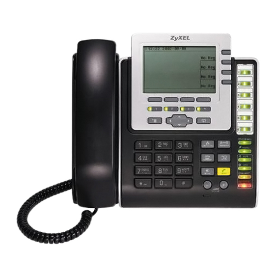
Page 36: Table 2 Front Panel Hardware
Chapter 2 Hardware The following table describes the front panel hardware. Table 2 Front Panel Hardware LABEL DESCRIPTION Handset. LCD (Liquid Crystal Display) screen. Account keys Softkeys Line keys Menu Navigator Phonebook Use these to select the SIP account you want to use. You can configure up to four SIP accounts on the V500. - Page 37 Table 2 Front Panel Hardware (continued) LABEL DESCRIPTION Action keys Alphanumeric keypad Microphone Volume keys V500 Series User’s Guide CONFERENCE Use this to set up a conference call between the V500 and two other phones, or to split a conference call you set up into two separate calls. TRANSFER Use this to transfer a call to another phone.
-
Page 38: Figure 5 Side Panel
Chapter 2 Hardware Table 2 Front Panel Hardware (continued) LABEL DESCRIPTION Function keys Custom keys Figure 5 Side Panel The following table describes the side panel hardware. Table 3 Side Panel Hardware LABEL DESCRIPTION Microphone socket Headphone socket The LEDs (lights) in these keys illuminate when they are active. VOICEMAIL Use this to check your voicemail messages, once the voicemail number is configured on the V500. -
Page 39: Figure 6 Rear Panel Hardware
V500). See your Quick Start Guide for details. Attach the included power adaptor, if you are not using Power over Ethernet (V501-T1 only). See the product specifications appendix for power supply specifications. Note: Use only the power adaptor and cable that came with your V500. -
Page 40: The Lcd Screen
Chapter 2 Hardware Table 4 Rear Panel Hardware LABEL DESCRIPTION Reset button Handset port Cable channels 2.2.1 The LCD Screen When the V500 is on, the LCD (Liquid Crystal Display) screen shows either the status screen, a phonebook screen, or a configuration menu. The LCD menus allow you to configure and control the V500. -
Page 41: Receiving A Call
• If you want to use a headset: Press the HEADSET key. 2 A Line key LED turns on. The LCD screen shows which SIP account you are using. Change these, if you want, using the Line and Account keys. 3 Check that you can hear a dial tone. -
Page 42: Muting A Call
Chapter 2 Hardware 2.3.5 Muting a Call When you mute a call on the V500 you can hear the incoming signal (the sound from the other end of the line) but you do not transmit a signal (the person on the other end of the line cannot hear you). -
Page 43: Transferring A Call
You cannot have a conference call and a transferred call ongoing at the same time. 2.3.9 Transferring a Call Take the following steps to transfer an ongoing call to another phone number. 1 During the ongoing call, press the Transfer key. 2 The next available line automatically activates, and the corresponding Line key lights up. - Page 44 Chapter 2 Hardware V500 Series User’s Guide...
-
Page 45: Tutorials
H A P T E R 3.1 Overview These tutorials show you how to perform numerous functions of the V500. Even though they make certain basic assumptions that may not match your actual configuration environment, the foundation provided here should be sufficient to get you up and running as quickly as possible. For complete information on how to work with the LCD menu screens, see Chapter 4 on page To get your V500 operational, you must:... - Page 46 Chapter 3 Tutorials 2 For Static IP: Open the IP (Off) option and press Select. Configure your static IP settings. Static IP 1 IP Address 2 Default Gateway 3 Subnet Mask 4 1st DNS 5 2nd DNS Select 3 For DHCP: Open the (Off) menu option and set it to On.
-
Page 47: Configuring Voip Options Automatically
3.3 Configuring VoIP Options Automatically Once you have established a network connection, the next thing you must do is configure the V500 so that it can connect to a voice server. If your voice server uses auto provisioning, then that server can automatically upload all the required VoIP configuration data directly to your phone;... -
Page 48: Configuring Voip Options Manually
Chapter 3 Tutorials 3.3.1 Configuring VoIP Options Manually If your phone network does not use or support automatic configuration through auto provisioning, then you must configure the V500’s voice server settings yourself. The essential settings you need to establish a VoIP connection are: SETTING Display Name SIP Number... - Page 49 2 The screen changes to display the SIP Configuration menu. provided for the following settings: SIP Register Server, SIP Auth ID and Auth Password. SIP 1 Configuration 1 Display Name 2 SIP Number 3 SIP Local Port 4 SIP Server Addr 5 SIP Server Port 6 SIP Register Server 7 SIP Register Port...
-
Page 50: Placing A Call
Chapter 3 Tutorials 3.4 Placing a Call Placing a phone call on your V500 is as easy as with any other phone, although you have a greater variety of options available to you with this one. First and foremost you can have up to 4 separate phone lines with their own VoIP numbers all on the same unit so choosing which line to use may seem like a daunting task (it’s not, but if this is your first experience with the V500 it is easy to understand how it could be). -
Page 51: Receiving An Incoming Call On A 2Nd Line
3.4.1 Receiving an Incoming Call on a 2nd Line Now that you know how to place calls, we’re going to show you how to retrieve an incoming call on a second VoIP number if you’re already talking on a first one. For example, let’s say you’re talking to Jasmine on Line 1 (using VoIP account ‘1001’, from our previous examples) and Sebastian calls in on Line 2 (or VoIP account ‘1002’). - Page 52 Chapter 3 Tutorials 3 Press the Line key of the incoming call to answer it. Here, it is Line 2. The V500 LCD screen changes to indicate your selection and the call for Line 2 becomes active. The Line 1 key flashes to indicate a call on hold while the Line 2 key shines a steady green to indicate is currently in use.
-
Page 53: Making A Conference Call
3.5 Making a Conference Call A conference call consists of three connected phones (including yours) participating in the same conversion simultaneously. To make a conference call: 1 Dial the number of the first person in your conference call. 2 When your party answers, press the 3 The V500 puts the first party on hold and prompts you to select a line number. - Page 54 Chapter 3 Tutorials 5 When they answer, press the the conference call. Your V500 LCD screen should look similar to this: 3:30 2008-11-21 Line 1 To: Jasmine Line 2 To: Sebastian The end result is that the call to Jasmine goes out on Line 1 (or number 1001) while the call to Sebastian goes out on Line 2 (or number 1002).
-
Page 55: Retrieving Voice Mail
3.6 Retrieving Voice Mail When you dial a number and the person at the other end does not pick up, you are prompted to leave a voice mail or dial another extension. This tutorial shows you how to listen to any voice mail messages that you might have received. - Page 56 Chapter 3 Tutorials 2 To retrieve your voice mail messages, press the LED directly to the audio prompt. Simply follow the instructions as they are presented to you. 3 Alternatively, you can press Soft Key 2, which corresponds to the voice mail icon that appears in the Main screen;...
-
Page 57: Setting The Time On Your V500
3.7 Setting the Time on Your V500 By default, your phone’s time is set automatically using an external time server. However, you can set the time manually as well. This tutorial takes you directly to the V500’s operating system: the Web Configurator. To set the time on your V500: 1 First, we need to get your phone’s IP address. - Page 58 Chapter 3 Tutorials 3 Open the Maintenance > System > Time Setting screen, and configure your V500’s time settings as you see fit. V500 Series User’s Guide...
-
Page 59: Lcd Screen Menus
LCD Screen Menus Using the LCD Screen (61) The Phonebook (69) LCD Menus: Basic Settings (77) LCD Menus: Advanced (103) -
Page 61: Using The Lcd Screen
H A P T E R Using the LCD Screen 4.1 Overview This chapter shows how to use and configure the V500 via the LCD screen menu system. For a complete overview of the V500’s navigation and keypad buttons, please refer to Section 1 of the Quick Start Guide. -
Page 62: The Keypad
Chapter 4 Using the LCD Screen The following table describes the navigation pad features. FEATURE DESCRIPTION Softkeys These keys’ functions depend on the screen currently displayed on the LCD screen. A word or symbol displayed on the LCD screen above a softkey shows its current function. -
Page 63: Working With The Lcd Menus
4.4 Working with the LCD Menus Once you are familiar with the navigation and keypads, it is actually quite easy to move about within the LCD menu system. As described in previous sections, the navigation pad gives you the freedom to open menus and make menu selections while the keypad allows you to configure the specific features that require your direct input. -
Page 64: Entering Numbers, Letters And Symbols
Chapter 4 Using the LCD Screen 4.4.2 Entering Numbers, Letters and Symbols When you enter information into the V500 (when setting up a phonebook entry, for example) you may need to enter different kinds of characters. The alphanumeric keypad has four input modes: •... -
Page 65: Lcd Menu Overview
1 Press the MENU key to enter the menu system. 2 Select Advanced Setting. 3 Use the navigator to highlight Auto Provision (Off). 4 Press the On softkey. 5 Press the Select softkey. You can enable and disable a sub-feature only when you first enable the feature. - Page 66 Chapter 4 Using the LCD Screen Table 6 LCD Menu Overview (continued) MENU Call Receive Anonymous Call Preference Call Forward Phonebook Contact List Group Block List DND White List Speed Dial Advanced Network Setting Setting Configuration Auto Provision Programmable Key Display Adjusting Call Feature...
-
Page 67: The Lcd Status Screen
Table 6 LCD Menu Overview (continued) MENU System Restart Logo Setting 4.7 The LCD Status Screen When you first turn on the V500 or make a call, the status screen displays. The status screen is divided into four main sections, as shown below. Figure 10 LCD Status Screen 03:30 2007-11-21 ZyXEL... - Page 68 Chapter 4 Using the LCD Screen V500 Series User’s Guide...
-
Page 69: The Phonebook
H A P T E R 5.1 Overview Use the V500’s phonebook to store the names and phone numbers of your contacts. You can either add phonebook entries yourself, or they can be supplied via auto provisioning. The following sections describe how to add, edit, delete and use phonebook entries. 5.2 Add a Phonebook Entry Take the following steps to add a contact’s entry to the V500’s phonebook. -
Page 70: Figure 12 Lcd Contact List
Chapter 5 The Phonebook 3 The Contact List screen displays. Figure 12 LCD Contact List Private Phonebook 1. Andrew 912345 2. Bob 923456 3. Connie 934567 Edit You can also access the Contact List screen by pressing the MENU key and selecting Phonebook >... -
Page 71: Figure 14 Lcd Caller Group
Figure 14 LCD Caller Group Caller Group 1 Default 2 Family 3 Business 4 Friend 5 Others Select • Select the group to which you want to add this contact. When the contact calls you, the V500 uses the ring tone you configure in the Ring Setting menu. •... -
Page 72: Edit A Phonebook Entry
Chapter 5 The Phonebook Figure 16 LCD Assign Account Speed Dial Key 1 Key 2 Key 3 Key 4 Key 5 Key 6 Key 7 Key 8 Select Select the numeric keypad key you want to use for this contact from the list, and press Select. -
Page 73: Delete A Phonebook Entry
5.4 Delete a Phonebook Entry Take the following steps to remove a contact’s entry from the phonebook. 1 Press the PHONEBOOK key. The Contact List screen displays. Scroll down to the entry. Press Delete. The Contact List - Delete screen displays. Figure 18 LCD Contact List - Delete Contact List - Delete Delete Bob? -
Page 74: Search By Number
Chapter 5 The Phonebook 5.5.1 Search by Number Take the following steps to search the phonebook by number. 1 Begin to type in the phone number. The LCD automatically displays all phonebook entries that match the initial dialed number. For example, if you enter “9”, the LCD displays all entries whose phone numbers begin with a 9. -
Page 75: Search By Name
Figure 21 LCD Search by Number Example 2 23:58 2007-04-20 Line 1 To: 1 945678 Dawn Select 3 Highlight the entry you want to call using the navigator, and press Select to begin the call. 5.5.2 Search by Name Take the following steps to search the phonebook by name. 1 Press the PHONEBOOK key. - Page 76 Chapter 5 The Phonebook V500 Series User’s Guide...
-
Page 77: Lcd Menus: Basic Settings
H A P T E R LCD Menus: Basic Settings 6.1 Overview This chapter discusses how to set up your V500 using the internal configuration menus. 6.2 Entering the Menu System Press the MENU key on the V500’s front panel to enter the menu system. The Menu Setting screen displays as shown below. -
Page 78: The System Info Menu
Chapter 6 LCD Menus: Basic Settings 6.3 The System Info Menu The System Info menu allows you to quickly check some of your V500’s settings. These settings are read-only. Press MENU > System Info. The following screen displays. Figure 23 LCD Menu: System Info System Name 1 Firmware Version 2 IP Address... -
Page 79: Firmware Version
6.3.1 Firmware Version Use these menus to check your V500’s firmware version. Select Firmware Version in the System Info menu. The following screen displays. Figure 24 LCD Menu: Firmware Version Firmware Version 1.99(AOZ.2)b1 You can upload new firmware using the web configurator. Press Back to return to the previous menu. -
Page 80: Voip Status
Chapter 6 LCD Menus: Basic Settings Table 9 LCD Menu: IP Address LABEL Gateway DNS1 DNS2 Back 6.3.3 VoIP Status Use this screen to check the SIP number associated with each VoIP account configured on the V500, and to see whether an account is correctly registered with a SIP server. Select VoIP Status in the System Info menu. -
Page 81: The Ring Setting Menu
6.4 The Ring Setting Menu The Ring Setting menu allows you to set the V500 to ring differently when certain people call you. This depends on the group that the person’s phonebook entry belongs to. To have the V500 ring differently when someone calls you, you must do the following things: •... -
Page 82: The Ring Type Menu
Chapter 6 LCD Menus: Basic Settings 6.4.1 The Ring Type Menu Use this menu to audition and select ring tones for each call group. Select one of the options in the Ring Setting menu. The following screen displays (this example uses the Others group). Figure 28 LCD Menu: Ring Type Other Ring Type Chirp 0... -
Page 83: Volume Screen
The following table describes the labels in this screen. Table 13 LCD Menu: Volume Setting LABEL Speaker Volume Phone Volume Ring Volume Headset Volume Select Back 6.5.1 Volume Screen When you select one of the options in the Volume Setting menu, a screen similar to the following displays. -
Page 84: The Call Preference Menu
Chapter 6 LCD Menus: Basic Settings 6.6 The Call Preference Menu Use these menus to allow or prohibit incoming calls that do not carry caller ID information, and to set up call forwarding. Select Call Preference. The following screen displays. Figure 31 LCD Menu: Call Preference Call Preference 1 Recv. -
Page 85: Call Forward
6.6.1 Call Forward Use these menus to set up and activate different kinds of call redirection for incoming calls. Enable and select Call Preference > Call Forward. The following screen displays. Figure 32 LCD Menu: Call Forward Call Forward 1 Unconditional Fwd (Off) 2 Conditional Fwd (On) 3 Forward Number: 0 6 Specific Forward (On) -
Page 86: Figure 33 Lcd Menu: Conditional Forward
Chapter 6 LCD Menus: Basic Settings 6.6.1.1 Conditional Forward Use this menu to specify the conditions under which you want calls to be redirected. Enable and select Call Preference > Call Forward > Conditional Forward. The following screen displays. Figure 33 LCD Menu: Conditional Forward Conditional Forward 1 On Busy Forward (Off) 2 No Answer Forward (On) -
Page 87: Figure 34 Lcd Menu: Forward Number
Select Call Preference > Call Forward > Forward Number. The following screen displays. Figure 34 LCD Menu: Forward Number Call Forward Current: Edit The following table describes the labels in this screen. Table 18 LCD Menu: Forward Number LABEL Current Edit Back 6.6.1.2.1 Forward Number - Edit... -
Page 88: Figure 36 Lcd Menu: Specific Forward Entry Table
Chapter 6 LCD Menus: Basic Settings The following table describes the labels in this screen. Table 19 LCD Menu: Forward Number - Edit LABEL Current Save <- Back 6.6.1.3 Specific Forward These menus allow you to set the V500 to recognize incoming calls from a certain particular number and then redirect the calls to another number. -
Page 89: Figure 37 Lcd Menu: Specific Forward Entry
6.6.1.3.1 Specific Forward Entry Use the specific forward entries to specify the incoming caller’s number, the number to which you want the call to be redirected, and the conditions under which it should be redirected. When you enable and select an Entry in the Specific Forward Entry Table menu, the following menu displays. -
Page 90: Figure 38 Lcd Menu: Incoming Call Number
Chapter 6 LCD Menus: Basic Settings Figure 38 LCD Menu: Incoming Call Number Incoming Call Number Current: 1234 Edit 2 Press Edit. Enter the new incoming call number and press Save. The Specific Forward Entry menu displays. 3 Select Forward to Number. The following screen displays. Figure 39 LCD Menu: Forward to Number Forward to Number Current: 5678... -
Page 91: The Phonebook Menu
Figure 40 LCD Menu: Condition Condition 1 Unconditional (On) 2 Busy Forward (Off) 3 NoAnswer Forward (Off) 4 DND Active (Off) 6 Select the conditions under which you want calls from this number to be redirected. • Enable Unconditional to have the V500 always redirect calls from this number. •... -
Page 92: Contact List
Chapter 6 LCD Menus: Basic Settings The following table describes the labels in this screen. Table 22 LCD Menu: Phonebook LABEL Contact List Group Block List DND White List Speed Dial Select Back 6.7.1 Contact List Use the Contact List to add, edit or remove entries from the phonebook. Use the navigator and press the yellow SEND key to call the selected entry (the V500 uses the speakerphone and the default line and SIP account to make the call). -
Page 93: Figure 42 Lcd Menu: Caller Group
Figure 42 LCD Menu: Caller Group Caller Group 1 Default 2 Family 3 Business 4 Friend 5 Others Select The following table describes the labels in this screen. Table 23 LCD Menu: Caller Group LABEL Default / Family / Business / Friend / Others Select Back... -
Page 94: Block List
Chapter 6 LCD Menus: Basic Settings 6.7.3 Block List This shows the phone numbers that are barred from calling you. When you are called from a number on the Block List, the V500 does not ring. You can either configure the numbers you want to block in this screen (press Add) or set an entry in the Contact List to be blocked. -
Page 95: Dnd White List
6.7.4 DND White List This shows which of your contacts can call you when DND (Do Not Disturb) is turned on. When someone on the DND White List calls, the V500 rings whether DND is on or not. Only entries in your Contact List can be in the DND White List. Select Phonebook >... -
Page 96: The Speed Dial Menu
Chapter 6 LCD Menus: Basic Settings 6.7.5 The Speed Dial Menu This menu allows you to set up one-touch calling. You can map a phone number to an alphanumeric keypad key (0 to 9) and then use that keypad key to call the phone number (press and hold the key for one second or longer). -
Page 97: Figure 47 Lcd Menu: Speed Dial - Edit
6.7.5.2 The Speed Dial - Edit Screen The Speed Dial - Edit screen allows you to add and change the phone numbers that are mapped onto the alphanumeric keys. Press Edit in the Speed Dial screen. A screen similar to the following displays (this example uses the screen for the 0 alphanumeric key). -
Page 98: The Advanced Setting Menu
Chapter 6 LCD Menus: Basic Settings 6.7.5.2.1 Speed Dial - Edit Phonebook Take the following steps to map a phonebook entry to a speed dial key 1 Press Pbook in the Speed Dial screen. The following screen displays. Figure 48 LCD Menu: Speed Dial - Edit Phonebook Phonebook 1 Public 2 Private... -
Page 99: The System Restart Menu
6.9 The System Restart Menu Use this screen to restart the V500 without turning the power off. Select System Restart. The following screen displays. Figure 49 LCD Menu: System Restart System Restart Restart System ? The following table describes the labels in this screen. Table 28 LCD Menu: System Restart LABEL V500 Series User’s Guide... -
Page 100: The Logo Setting Menu
Chapter 6 LCD Menus: Basic Settings 6.10 The Logo Setting Menu Use this screen to set the logo that appears in the main screen when the phone is idle. By default, the logo is “ZyXEL” but you can, of course, change this to whatever you want (such as your own company name or a department number, for example). -
Page 101: The Logo Setting - Edit Screen
6.10.1 The Logo Setting - Edit Screen Use this screen to change your V500’s existing logo. Figure 51 LCD Menu: Logo Setting - Edit Logo Font - Edit New: _ The following table describes the labels in this screen. Table 30 LCD Menu: Logo Setting - Edit LABEL <- Back... - Page 102 Chapter 6 LCD Menus: Basic Settings V500 Series User’s Guide...
-
Page 103: Lcd Menus: Advanced
H A P T E R LCD Menus: Advanced 7.1 Overview This chapter discusses using the V500’s Advanced LCD menus. 7.1.1 What You Can Do in This Chapter • Set up your V500’s IP address - see 115. • Set up PPPoE (Point-to-Point Protocol over Ethernet) - see •... -
Page 104: The Network Setting Menu
Chapter 7 LCD Menus: Advanced 7.3 The Network Setting Menu Use these menus to configure the V500’s IP address, and PPPoE username and password. Select Advanced Setting > Network Setting. The following screen appears. Figure 53 LCD Menu: Network Setting Network Setting 1 PPPoE (Off) 2 Static IP (Off) -
Page 105: The Pppoe Menu
7.3.1 The PPPoE Menu Use this menu to configure your V500’s PPPoE username and password, if it is a PPPoE client. Enter your details exactly as your ISP or network administrator gave them to you. Enable and select Advanced Setting > Network Setting > PPPoE. The following screen displays. -
Page 106: Figure 55 Lcd Menu: Pppoe Username
Chapter 7 LCD Menus: Advanced 7.3.1.1 PPPoE Username Enable and select Advanced Setting > Network Setting > PPPoE > Username. The following screen displays. Figure 55 LCD Menu: PPPoE Username PPPoE Username Current: Edit The following table describes the labels in this screen. Table 33 LCD Menu: PPPoE Username LABEL Current... -
Page 107: Figure 57 Lcd Menu: Pppoe Password
The following table describes the labels in this screen. Table 34 LCD Menu: PPPoE Username - Edit LABEL Current Mode Save <- Cancel 7.3.1.2 PPPoE Password Enable and select Advanced Setting > Network Setting > PPPoE > Password. The following screen displays. Figure 57 LCD Menu: PPPoE Password PPPoE Password Current: ****... -
Page 108: Figure 58 Lcd Menu: Pppoe Password - Edit
Chapter 7 LCD Menus: Advanced 7.3.1.2.1 PPPoE Password - Edit Press Edit in the PPPoE > PPPoE Password screen. The following screen displays. Figure 58 LCD Menu: PPPoE Password - Edit PPPoE Password Current: **** New: Confirm: Save The following table describes the labels in this screen. Table 36 LCD Menu: PPPoE Username - Edit LABEL Current... -
Page 109: Static Ip
7.3.2 Static IP Use this menu to manually configure your V500’s IP address, subnet mask and gateway settings. Enter the settings exactly as your ISP or network administrator gave them to you. Enable and select Advanced Setting > Network Setting > Static IP. The following screen displays. -
Page 110: Figure 60 Lcd Menu: Ip Address
Chapter 7 LCD Menus: Advanced 7.3.2.1 IP Address Enable and select Advanced Setting > Network Setting > Static IP > IP Address. The following screen displays. Figure 60 LCD Menu: IP Address Static IP Current: 192.168.1.1 Edit The following table describes the labels in this screen. Table 38 LCD Menu: IP Address LABEL Current... -
Page 111: Figure 62 Lcd Menu: Default Gateway
The following table describes the labels in this screen. Table 39 LCD Menu: IP Address - Edit LABEL Current Mode Save <- Cancel 7.3.2.2 Default Gateway Enable and select Advanced Setting > Network Setting > Static IP > Default Gateway. The following screen displays. -
Page 112: Figure 63 Lcd Menu: Default Gateway - Edit
Chapter 7 LCD Menus: Advanced 7.3.2.2.1 Default Gateway - Edit Press Edit in the Default Gateway screen. The following screen displays. Figure 63 LCD Menu: Default Gateway - Edit Static Gateway Current: 192.168.1.254 New: Save The following table describes the labels in this screen. Table 41 LCD Menu: Default Gateway - Edit LABEL Current... -
Page 113: Figure 64 Lcd Menu: Subnet Mask
7.3.2.3 Subnet Mask Enable and select Advanced Setting > Network Setting > Static IP > Subnet Mask. The following screen displays. Figure 64 LCD Menu: Subnet Mask Subnet Mask Current: 255.255.255.0 Edit The following table describes the labels in this screen. Table 42 LCD Menu: Subnet Mask LABEL Current... -
Page 114: Figure 66 Lcd Menu: First / Second Dns
Chapter 7 LCD Menus: Advanced The following table describes the labels in this screen. Table 43 LCD Menu: Subnet Mask - Edit LABEL Current Mode Save <- Cancel 7.3.2.4 First and Second DNS Servers Use these screens to enter the IP address(es) of DNS (Domain Name System) servers on your network. -
Page 115: Dhcp
7.3.2.4.1 First / Second DNS - Edit Press Edit in the 1st DNS or 2nd DNS screen. A screen similar to the following displays (this example uses the 1st DNS screen). Figure 67 LCD Menu: First / Second DNS - Edit 1st DNS Current: 0.0.0.0 New:... -
Page 116: The Sip Configuration Menus
Chapter 7 LCD Menus: Advanced 7.4 The SIP Configuration Menus Use these menus to set up your V500 to use your existing Voice over Internet (VoIP) account(s). You can configure up to four VoIP accounts on the V500. Once you have configured the fields in these menus with the correct information, the V500 must register with the SIP server. -
Page 117: Display Name
Table 46 LCD Menu: SIP Account Configuration (continued) SIP Server Port SIP Register Server SIP Register Port SIP Service Domain SIP Auth ID Auth Password Codec Priority Voicemail Number DNS SRV (On/Off) Call ID (On) NAT Setting Backup SIP Server 7.4.1 Display Name Use this screen to change the name that appears in the LCD screen tab for this account. -
Page 118: Sip Number
Chapter 7 LCD Menus: Advanced 7.4.1.1 Account Name - Edit Press Edit in the Account Name screen. The following screen displays. Figure 70 LCD Menu: Display Name - Edit Account Name Current: New: Save The following table describes the labels in this screen. Table 48 LCD Menu: Display Name - Edit LABEL Current... -
Page 119: Figure 71 Lcd Menu: Sip Number
Select Advanced Settings > SIP Configuration > SIP (1 ~ 4) Configuration > SIP Number. The following screen displays. Figure 71 LCD Menu: SIP Number SIP Number Current: 1234 Edit The following table describes the labels in this screen. Table 49 LCD Menu: SIP Number LABEL Current Edit... -
Page 120: Sip Local Port
Chapter 7 LCD Menus: Advanced The following table describes the labels in this screen. Table 50 LCD Menu: SIP Number - Edit LABEL Current Mode Save <- Cancel 7.4.3 SIP Local Port Use this screen to see and edit the port on the V500 this account uses to listen for incoming SIP calls. -
Page 121: Figure 74 Lcd Menu: Sip Local Port - Edit
7.4.3.1 SIP Local Port - Edit Press Edit in the SIP Local Port screen. The following screen displays. Figure 74 LCD Menu: SIP Local Port - Edit SIP Local Port Current: 5060 New: Save The following table describes the labels in this screen. Table 52 LCD Menu: SIP Local Port - Edit LABEL Current... -
Page 122: Sip Server Address
Chapter 7 LCD Menus: Advanced 7.4.4 SIP Server Address Use this menu to see and edit the IP address of the SIP server for this account. Select Advanced Setting > SIP Configuration > SIP (1 ~ 4) Configuration > SIP Server Addr. The following screen displays. -
Page 123: Sip Server Port
The following table describes the labels in this screen. Table 54 LCD Menu: SIP Server Address - Edit LABEL Current Mode Save <- Back 7.4.5 SIP Server Port Use this screen to see and edit the port on the this account’s SIP server used for SIP calls. Select Advanced Setting >... -
Page 124: Figure 78 Lcd Menu: Sip Server Port - Edit
Chapter 7 LCD Menus: Advanced 7.4.5.1 SIP Server Port - Edit Press Edit in the SIP Server Port screen. The following screen displays. Figure 78 LCD Menu: SIP Server Port - Edit SIP Server Port Current: 5060 New: Save The following table describes the labels in this screen. Table 56 LCD Menu: SIP Server Port - Edit LABEL Current... -
Page 125: Sip Register Server
7.4.6 SIP Register Server Use this menu to see and edit the IP address of the server your service provider uses to register the V500 for this account (also known as a registrar server). Select Advanced Setting > SIP Configuration > SIP (1 ~ 4) Configuration > SIP Register Server. The following screen displays. -
Page 126: Sip Register Port
Chapter 7 LCD Menus: Advanced The following table describes the labels in this screen. Table 58 LCD Menu: SIP Register Server Address - Edit LABEL Current Mode Save <- Back 7.4.7 SIP Register Port Use this screen to see and edit the listening port on the SIP registrar server for calls from this account. -
Page 127: Figure 82 Lcd Menu: Sip Register Port - Edit
7.4.7.1 SIP Register Port - Edit Press Edit in the SIP Register Port screen. The following screen displays. Figure 82 LCD Menu: SIP Register Port - Edit SIP Register Port Current: 5060 New: Save The following table describes the labels in this screen. Table 60 LCD Menu: SIP Register Port - Edit LABEL Current... -
Page 128: Sip Service Domain
Chapter 7 LCD Menus: Advanced 7.4.8 SIP Service Domain Use this to see and edit the SIP service domain configured for this SIP account. The SIP service domain of the VoIP service provider (the company that lets you make phonecalls over the Internet) is the domain name in a SIP URI. -
Page 129: Sip Authentication Id
The following table describes the labels in this screen. Table 62 LCD Menu: SIP Service Domain - Edit LABEL Current Mode Save <- Back 7.4.9 SIP Authentication ID A SIP account’s authentication ID is its username. Select Advanced Setting > SIP Configuration >... -
Page 130: Figure 86 Lcd Menu: Sip Authentication Id - Edit
Chapter 7 LCD Menus: Advanced 7.4.9.1 SIP Authentication ID - Edit Press Edit in the SIP Auth ID screen. The following screen displays. Figure 86 LCD Menu: SIP Authentication ID - Edit SIP Auth ID Current: New: Save The following table describes the labels in this screen. Table 64 LCD Menu: SIP Authentication ID - Edit LABEL Current... -
Page 131: Authentication Password
7.4.10 Authentication Password Use this screen to see and edit the password for this SIP account. Select Advanced Setting > SIP Configuration > SIP (1 ~ 4) Configuration > Auth Password. The following screen displays. Figure 87 LCD Menu: Authentication Password Auth Password Current: **** Edit... -
Page 132: Codec Priority
Chapter 7 LCD Menus: Advanced The following table describes the labels in this screen. Table 66 LCD Menu: Authentication Password - Edit LABEL Current Confirm Mode Save <- Cancel 7.4.11 Codec Priority When the V500 makes a SIP call, it negotiates the voice codec (coder / decoder) it uses for the call with the SIP server. -
Page 133: Voicemail Number
Press Change to cycle through the available codecs. Press Apply to save your changes and return to the previous menu, or press Back to return to the previous menu without saving. See the section on voice coding and decoding in the web configurator section for information on each of the codecs. -
Page 134: Dns Srv / Dns
Chapter 7 LCD Menus: Advanced 7.4.12.1 Voicemail Number - Edit Press Edit in the Voicemail Number screen. The following screen displays. Figure 91 LCD Menu: Voicemail Number - Edit Voicemail Number Current: **** New: Save The following table describes the labels in this screen. Table 68 LCD Menu: Voicemail Number - Edit LABEL Current... -
Page 135: Call Id
7.4.14 Call ID Turn this On to have the V500 send caller ID for outgoing calls. The person you call can tell who is calling. Turn this Off if you want the V500 not to send caller ID. 7.4.15 NAT Setting Use these menus to configure NAT (Network Address Translation) on the V500. -
Page 136: Figure 93 Lcd Menu: Stun
Chapter 7 LCD Menus: Advanced 7.4.15.1 STUN Use this menu to have the V500 get NAT information automatically from a STUN server. Enable and select Advanced Setting > SIP Configuration > SIP (1 ~ 4) Configuration > NAT Setting > STUN. The following screen displays. Figure 93 LCD Menu: STUN STUN 1 Server Addr... -
Page 137: Figure 95 Lcd Menu: Stun Server Address - Edit
The following table describes the labels in this screen. Table 70 LCD Menu: STUN Server Address LABEL Current Edit Back Press Edit in the STUN Server Address screen. The following screen displays. Figure 95 LCD Menu: STUN Server Address - Edit Server Address Current: New:... -
Page 138: Figure 96 Lcd Menu: Stun Server Port
Chapter 7 LCD Menus: Advanced 7.4.15.1.2 STUN Server Port Use this menu to see or edit the port number on the STUN server. Enable and select Advanced Setting > SIP Configuration > SIP (1 ~ 4) Configuration > NAT Setting > STUN > Server Port. -
Page 139: Figure 98 Lcd Menu: Outbound Proxy
The following table describes the labels in this screen. Table 73 LCD Menu: STUN Server Port - Edit LABEL Current Mode Save <- Back 7.4.15.2 Outbound Proxy Use this menu to have the V500 use an outbound proxy server. Enable and select Advanced Setting >... -
Page 140: Figure 99 Lcd Menu: Outbound Proxy Server Address
Chapter 7 LCD Menus: Advanced 7.4.15.2.1 Outbound Proxy Server Address Use this menu to see or edit the IP address of the outbound proxy server you want to use. Enable and select Advanced Setting > SIP Configuration > SIP (1 ~ 4) Configuration > NAT Setting >... -
Page 141: Figure 101 Lcd Menu: Outbound Proxy Server Port
The following table describes the labels in this screen. Table 76 LCD Menu: Outbound Proxy Server Address - Edit LABEL Current Mode Save <- Back 7.4.15.2.2 Outbound Proxy Server Port Use this menu to see or edit the port number on the outbound proxy server. Enable and select Advanced Setting >... -
Page 142: Backup Sip Server (1 And 2)
Chapter 7 LCD Menus: Advanced Press Edit in the Outbound Proxy Server Port screen. The following screen displays. Figure 102 LCD Menu: Outbound Proxy Server Port - Edit Server Port Current:5060 New: Save The following table describes the labels in this screen. Table 78 LCD Menu: Outbound Proxy Server Port - Edit LABEL Current... -
Page 143: Figure 103 Lcd Menu: Backup Sip Server
Select Advanced Setting > SIP Configuration > SIP (1 ~ 4) Configuration > Backup SIP Server. The following screen displays. Figure 103 LCD Menu: Backup SIP Server Backup SIP Server 1 1st Backup SIP Server (Off) 2 2nd Backup SIP Server (Off) Select Enable and select the backup SIP server you want to configure, or press Back to return to the previous screen. -
Page 144: The Auto Provision Menus
Chapter 7 LCD Menus: Advanced The following table describes the labels in this screen. Table 79 LCD Menu: First / Second Backup SIP Server LABEL SIP Server Address SIP Server Port Register Address Register Port SIP Server Domain Select Back 7.5 The Auto Provision Menus Use these menus if you have an auto-provisioning server on the network. -
Page 145: Protocol
Table 80 LCD Menu: Auto Provision LABEL Expire Time Retry Time Select Back 7.5.1 Protocol Use this screen to see or edit the protocol that the V500 uses to request and receive the auto- provisioning file. This protocol must be the same as that used by the auto-provisioning server. Enable and select Advanced Setting >... -
Page 146: Auto-Provisioning Server Address
Chapter 7 LCD Menus: Advanced Figure 107 LCD Menu: Auto Provision Protocol - Edit Auto Provision Protocol 1 TFTP 2 HTTP 3 HTTPS Save The following table describes the labels in this screen. Table 82 LCD Menu: Auto Provision Protocol - Edit LABEL TFTP HTTP... -
Page 147: Figure 109 Lcd Menu: Auto Provision Server Address - Edit
The following table describes the labels in this screen. Table 83 LCD Menu: Auto Provision Server Address LABEL Current Edit Back 7.5.2.1 Auto-provisioning Server Address - Edit Press Edit in the Server Address screen. The following screen displays. Figure 109 LCD Menu: Auto Provision Server Address - Edit Server Address Current: New:... -
Page 148: Auto-Provisioning Server Port
Chapter 7 LCD Menus: Advanced 7.5.3 Auto-provisioning Server Port Use this screen to see or edit the listening port of the auto-provisioning server from which the V500 gets the auto-provisioning file. Enable and select Advanced Setting > Auto Provision > Port. The following screen displays. Figure 110 LCD Menu: Auto Provision Server Port Server Port Current:... -
Page 149: Expire Time
The following table describes the labels in this screen. Table 86 LCD Menu: Auto Provision Server Port - Edit LABEL Current Mode Save <- Back 7.5.4 Expire Time Use this screen to see or edit the length of time the V500 waits after receiving an auto- provisioning file before it requests another. -
Page 150: Figure 113 Lcd Menu: Auto Provision Expire Time - Edit
Chapter 7 LCD Menus: Advanced 7.5.4.1 Expire Time - Edit Press Edit in the Expire Time screen. The following screen displays. Figure 113 LCD Menu: Auto Provision Expire Time - Edit Expire Time Current Timeout (sec):3600 New Timeout (sec): Save The following table describes the labels in this screen. -
Page 151: Retry Time
7.5.5 Retry Time Use this screen to see or edit the length of time the V500 waits if it cannot get an auto- provisioning file from the server before trying again. Enable and select Advanced Setting > Auto Provision > Retry Time. The following screen displays. -
Page 152: Programmable Key
Chapter 7 LCD Menus: Advanced The following table describes the labels in this screen. Table 90 LCD Menu: Auto Provision Expire Time - Edit LABEL Current Timeout New Timeout Mode Save <- Back 7.6 Programmable Key The V500 has six custom keys (see configure these keys to perform call functions. -
Page 153: Display Adjusting
The following table describes the labels in this screen. Table 91 LCD Menu: Programmable Key LABEL Key 1 ~ Key 6 <- Apply Back 7.7 Display Adjusting Use this menu to change the way the LCD screen displays. You can change the screen’s brightness and contrast levels. -
Page 154: Contrast
Chapter 7 LCD Menus: Advanced 7.7.1 Contrast Use this menu to change the LCD screen’s contrast (the difference between the text shade and the background shade). Select Contrast in the Display Adjusting menu. The following screen displays. Figure 118 LCD Menu: Contrast Contrast Apply Down... -
Page 155: Call Feature Mode
The following table describes the labels in this screen. Table 94 LCD Menu: Brightness LABEL Apply Down Cancel 7.8 Call Feature Mode Use this menu to switch between local mode and PBX mode. Figure 120 LCD Menu: Call Feature Mode Call Feature Mode 1 Local Mode (Off) 2 PBX Mode (On) -
Page 156: Pbx Mode
Chapter 7 LCD Menus: Advanced 7.8.1 PBX Mode Use this menu to configure the PBX mode settings. PBX mode should be selected if your phone connection is routed through a ZyXEL IP PBX (such as the X2002), or another IP-PBX. The settings here are automatically configured using auto-provisioning if routed through a ZyXEL device;... -
Page 157: Language Support
7.9 Language Support Use this menu to select the language used on the V500’s menus. This setting does not apply to the Web Configurator. Figure 122 LCD Menu: Language Support Language Support 1 English 2 French 3 German 4 Italian 5 Spanish 6 Czech 7 Russian... - Page 158 Chapter 7 LCD Menus: Advanced V500 Series User’s Guide...
-
Page 159: The Web Configurator
The Web Configurator Introducing the Web Configurator (161) Status Screens (167) Network Setup (173) SIP Account Setup (177) Phone Setup (193) The Phone Book (201) -
Page 161: Introducing The Web Configurator
H A P T E R 8.1 Overview This chapter describes how to access the V500’s web configurator and provides an overview of its screens. 8.2 Accessing the Web Configurator 1 Make sure your hardware is properly connected and prepare your computer or computer network to connect to the V500 (refer to the Quick Start Guide). -
Page 162: Figure 124 Change Password Screen
Chapter 8 Introducing the Web Configurator 4 Type “admin” as the username and "1234" (default) as the password, then click Login. 5 It is strongly recommended that you change your password in the screen that displays next. If you do not change your password, anyone who knows the default password can access your phonebook and SIP account information over the network. -
Page 163: Title Bar
The Status screen displays. Figure 125 The Status Screen As illustrated above, the web configurator screen is divided into four parts. • A - title bar • B - navigation panel • C - main window • D - status bar 8.2.1 Title Bar The title bar has some icons in the upper right corner. -
Page 164: Navigation Panel
Chapter 8 Introducing the Web Configurator 8.2.2 Navigation Panel Use the menu items on the navigation panel to open screens and configure the V500’s features. The following table describes the menu items. Table 99 Navigation Panel Summary LINK Status Network Ethernet Internet Connection... -
Page 165: Main Window
8.2.3 Main Window The main window displays information and configuration fields. It is discussed in the rest of this document. Right after you log in, the Status screen is displayed. See information about the Status screen. 8.2.4 Status Bar Check the status bar when you click Apply or OK to verify that the configuration has been updated. - Page 166 Chapter 8 Introducing the Web Configurator V500 Series User’s Guide...
-
Page 167: Status Screens
H A P T E R 9.1 Overview Use the Status screens to see the current status of the V500, its system resources, interfaces, and SIP accounts. You can also register and unregister SIP accounts. It also provides detailed traffic and VoIP statistics. 9.2 Status Screen Click Status to open this screen. -
Page 168: Table 100 Status Screen
Chapter 9 Status Screens Each field is described in the following table. Table 100 Status Screen LABEL Refresh Interval Refresh Now Device Information System Name Firmware Version IP Address IP Subnet Mask DHCP System Status System Uptime Current Date/ Time CPU Usage Memory Usage Interface Status... -
Page 169: Packet Statistics
Table 100 Status Screen LABEL Registration Summary VoIP Statistics Packet Statistics 9.3 Packet Statistics To access this screen, open the Status screen (see (Details...) next to Packet Statistics. Read-only information here includes port status and packet specific statistics. Also provided are "system up time" and "poll interval(s)". The Poll Interval(s) field is configurable. -
Page 170: Voip Statistics
Chapter 9 Status Screens Table 101 Packet Statistics (continued) LABEL RxPkts Collisions Tx B/s Rx B/s Up Time System up Time This is the elapsed time the system has been on. Poll Interval(s) Set Interval Stop 9.4 VoIP Statistics This screen displays SIP registration information, status of calls and VoIP traffic statistics. To access this screen, open the Status screen (see next to VoIP Statistics. - Page 171 Table 102 VoIP Statistics LABEL DESCRIPTION Registration This field displays the current registration status of the SIP account. You can change this in the Status screen. Registered - The SIP account is registered with a SIP server. Unregister - The SIP account has failed to register with a SIP server, or is not active.
- Page 172 Chapter 9 Status Screens Table 102 VoIP Statistics LABEL Poll Interval(s) Set Interval Stop DESCRIPTION Enter how often you want the V500 to update this screen, and click Set Interval. Click this to make the V500 update the screen based on the amount of time you specified in the Poll Interval field.
-
Page 173: Network Setup
H A P T E R 10.1 Overview This chapter discusses how to configure the V500’s network settings. 10.1.1 What You Can Do in This Chapter • The Internet Connection screen allows you change your V500’s Internet access settings (Section 10.2 on page •... - Page 174 Chapter 10 Network Setup Regardless of your particular situation, do not create an arbitrary IP address; always follow the guidelines above. For more information on address assignment, please refer to RFC 1597, Address Allocation for Private Internets and RFC 1466, Guidelines for Management of IP Address Space. IP Address and Subnet Mask Similar to the way houses on a street share a common street name, computers on a LAN share one common network number.
-
Page 175: Internet Connection
10.2 Internet Connection Use this screen to change your V500’s Internet access settings. Click Network > Internet Connection. Figure 129 Network > Internet Connection The following table describes the labels in this screen. Table 104 Network > Internet Connection LABEL DESCRIPTION Ethernet TCP/IP Settings Select this option if your ISP did not give you an IP address. -
Page 176: Management Port
Chapter 10 Network Setup 10.3 Management Port Use this screen to configure the management IP address of the V500. You can use this IP address to connect to the V500 even when its WAN IP address is in a different subnet. Your computer must be in the same subnet as the management IP address to use it. -
Page 177: Sip Account Setup
H A P T E R 11.1 Overview This chapter discusses the V500’s VoIP > SIP screens. 11.1.1 What You Can Do in This Chapter • The SIP Settings screen allows you to maintain basic information about each SIP account (Section 11.2 on page •... -
Page 178: Sip Settings Screen
Chapter 11 SIP Account Setup 11.2 SIP Settings Screen Use this screen to maintain basic information about each SIP account. Your VoIP service provider (the company that lets you make phone calls over the Internet) should provide this. You can also enable and disable each SIP account. To access this screen, click VoIP > SIP > SIP Settings. -
Page 179: Table 106 Voip > Sip > Sip Settings
Each field is described in the following table. Table 106 VoIP > SIP > SIP Settings LABEL DESCRIPTION SIP Settings SIP Account Select the SIP account you want to see in this screen. If you change this field, the screen automatically refreshes. Active Select this if you want the V500 to use this account. - Page 180 Chapter 11 SIP Account Setup Table 106 VoIP > SIP > SIP Settings LABEL SIP Service Port Register Service Address Register Service Port SIP Service Domain Authentication User Name Password Apply Advanced Setup DESCRIPTION Enter the backup SIP server’s listening port number, if your VoIP service provider gave you one.
-
Page 181: Advanced Sip Setup Screen
11.2.1 Advanced SIP Setup Screen Use this screen to maintain advanced settings for each SIP account. Click Advanced Setup in VoIP > SIP > SIP Settings. The following screen displays. Figure 132 VoIP > SIP > SIP Settings > Advanced V500 Series User’s Guide Chapter 11 SIP Account Setup... -
Page 182: Table 107 Voip > Sip > Sip Settings > Advanced Setup
Chapter 11 SIP Account Setup Each field is described in the following table. Table 107 VoIP > SIP > SIP Settings > Advanced Setup LABEL SIP Server Settings URL Type Expiration Duration Register Re- send timer Session Expires Active Session Expires Min-SE RTP Port Range... - Page 183 Table 107 VoIP > SIP > SIP Settings > Advanced Setup (continued) LABEL DESCRIPTION DTMF Mode Control how the V500 handles the alphanumeric keypad tones. You should use the same mode your VoIP service provider uses. RFC 2833 - send the DTMF tones in RTP packets PCM - send the DTMF tones in the voice data stream.
- Page 184 Chapter 11 SIP Account Setup Table 107 VoIP > SIP > SIP Settings > Advanced Setup (continued) LABEL Expiration Time Hot Line Enable Delay Period before Hotline Activated: Hotline Number: Call Forward Enable RingBack Active Enable MusicOnHold Active Enable PS (Presence Server) Server Address...
-
Page 185: Sip Qos Screen
11.3 SIP QoS Screen Use this screen to maintain ToS and VLAN settings for the V500. Click VoIP > SIP > QoS. The following screen displays. Figure 133 VoIP > SIP > QoS Each field is described in the following table. Table 108 VoIP >... -
Page 186: Table 109 Sip Call Progression
Chapter 11 SIP Account Setup SIP Identities A SIP account uses an identity (sometimes referred to as a SIP address). A complete SIP identity is called a SIP URI (Uniform Resource Identifier). A SIP account's URI identifies the SIP account in a way similar to the way an e-mail address identifies an e-mail account. The format of a SIP identity is SIP-Number@SIP-Service-Domain. -
Page 187: Figure 134 Sip User Agent
When you use SIP to make a VoIP call, it originates at a client and terminates at a server. A SIP client could be a computer or a SIP phone. One device can act as both a SIP client and a SIP server. -
Page 188: Figure 136 Sip Redirect Server
Chapter 11 SIP Account Setup SIP Redirect Server A SIP redirect server accepts SIP requests, translates the destination address to an IP address and sends the translated IP address back to the device that sent the request. Then the client device that originally sent the request can send requests to the IP address that it received back from the redirect server. -
Page 189: Figure 137 Stun
The V500 must register its public IP address with a SIP register server. If there is a NAT router between the V500 and the SIP register server, the V500 probably has a private IP address. The V500 lists its IP address in the SIP message that it sends to the SIP register server. NAT does not translate this IP address in the SIP message. - Page 190 Chapter 11 SIP Account Setup • G.711 is a Pulse Code Modulation (PCM) waveform codec. PCM measures analog signal amplitudes at regular time intervals (sampling) and converts them into digital bits (quantization). Quantization “reads” the analog signal and then “writes” it to the nearest digital value.
-
Page 191: Figure 138 Diffserv: Differentiated Service Field
MWI (Message Waiting Indication) Enable Message Waiting Indication (MWI) enables your phone to give you a message– waiting (beeping) dial tone when you have one or more voice messages. Your VoIP service provider must have a messaging system that sends message-waiting-status SIP packets as defined in RFC 3842. - Page 192 Chapter 11 SIP Account Setup Your V500 can add IEEE 802.1Q VLAN ID tags to voice frames that it sends to the network. This allows the V500 to communicate with a SIP server that is a member of the same VLAN group.
-
Page 193: Phone Setup
H A P T E R 12.1 Overview This chapter discusses the V500’s Phone screens. 12.1.1 What You Can Do in This Chapter • The Phone Settings screen allows you to configure basic phone settings like volume and ring tones (Section 12.2 on page •... -
Page 194: Phone Settings Screen
Chapter 12 Phone Setup 12.2 Phone Settings Screen Use this screen to configure basic phone settings like volume and ring tones. Click VoIP > Phone > Phone Settings. The following screen displays. Figure 139 VoIP > Phone > Phone Settings Each field is described in the following table. -
Page 195: Voice Activity Detection/Silence Suppression
Table 110 VoIP > Phone > Phone Settings LABEL DESCRIPTION Ring Volume Select this to set the volume of the V500’s ringtone. This setting applies to all configured group rings. 0 is the quietest and 12 is the loudest. Headset Select this to set the volume of an attached headset (or any device connected to Volume the external speaker and/or microphone sockets). -
Page 196: Comfort Noise Generation
Chapter 12 Phone Setup 12.2.2 Comfort Noise Generation When using VAD, the V500 generates comfort noise when the other party is not speaking. The comfort noise lets you know that the line is still connected as total silence could easily be mistaken for a lost connection. -
Page 197: Figure 141 Phone Book > Speed Dial
In peer-to-peer calls, you call another VoIP device directly without going through a SIP server. Enter the callee’s IP address or domain name. The V500 sends SIP INVITE requests to the peer VoIP device when you use the speed dial entry. You do not need to configure a SIP account in order to make a peer-to-peer VoIP call. -
Page 198: Programmable Feature Key Settings Screen
Chapter 12 Phone Setup 12.5 Programmable Feature Key Settings Screen You can program the custom keys on the V500 to automatically control certain supplementary call services, such as caller ID, call forwarding, call waiting, etc. These services are generally available from your VoIP service provider. The call functions available, and the codes you use to control them, may differ from one service provider to another. - Page 199 Table 113 Phone Book > Programmable Feature Key Settings LABEL Presence Key 1 ~ 6 Advanced Feature Key Settings CONFERENCE ~ SEND Apply Reset V500 Series User’s Guide DESCRIPTION Enter the presence “state” you want your phone to broadcast to other phones on the network when you press this feature key.
- Page 200 Chapter 12 Phone Setup V500 Series User’s Guide...
-
Page 201: The Phone Book
H A P T E R 13.1 Overview This chapter discusses the Phone Book screens. 13.1.1 What You Can Do in This Chapter • The Call Forward screen allows you to configure call forwarding for incoming calls (Section 13.2 on page •... -
Page 202: Call Forward Screen
Chapter 13 The Phone Book 13.2 Call Forward Screen Use this screen to configure call forwarding for incoming calls. When call forwarding is active, incoming calls are redirected to other phone numbers. You can set up rules for all incoming calls, or have the V500 forward calls from specific numbers only. Click VoIP >... - Page 203 Table 114 VoIP > Phone Book > Call Forward (continued) LABEL DESCRIPTION Conditional Select this to forward all incoming calls under certain circumstances (if the phone Forward is in use, if you do not answer, or if you have the Do Not Disturb function turned on).
-
Page 204: Contact List Screen
Chapter 13 The Phone Book Table 114 VoIP > Phone Book > Call Forward (continued) LABEL Busy Apply Reset 13.3 Contact List Screen Use this screen to see, add and edit details of your contacts. Click VoIP > Phone Book > Contact List. - Page 205 Table 115 VoIP > Phone Book > Contact List (continued) LABEL DESCRIPTION Modify Click the Add button to include the new entry in the phonebook, or to save the changes you made to an existing entry. Phone Book Table Page Select a page from the list to go to that page of contacts.
-
Page 206: Group List Screen
Chapter 13 The Phone Book 13.4 Group List Screen Use this screen to see and edit the calling groups to which your phonebook contacts belong. You can also edit this information in the VoIP > Phone Book > Contact List screen. -
Page 207: Block List Screen
13.5 Block List Screen Use this screen to see and edit details of the phone numbers that are prevented from making incoming calls to the V500. You can block up to 20 phone numbers. Click VoIP > Phone Book > Block List. The following screen displays. Figure 146 VoIP >... -
Page 208: Dnd White List Screen
Chapter 13 The Phone Book Table 117 VoIP > Phone Book > Block List (continued) LABEL Name Modify Apply Clear All 13.6 DND White List Screen Use this screen to see and edit details of people who can make incoming calls to the V500 even when you have DND (Do Not Disturb) turned on. -
Page 209: Table 118 Voip > Phone Book > Dnd White List
The following table describes the labels in this screen. Table 118 VoIP > Phone Book > DND White List LABEL DESCRIPTION DND White LIst Item This is the index number of the DND white list entry. Number Enter the phone number you want to add to the list. Name Enter a name for this entry, or leave this field blank. - Page 210 Chapter 13 The Phone Book V500 Series User’s Guide...
-
Page 211: Maintenance And Troubleshooting
Maintenance and Troubleshooting System (213) Logs (219) Tools (221) Troubleshooting (227) -
Page 213: System
H A P T E R 14.1 Overview Use the System screens to change the V500’s system and domain name settings, change the password or configure time settings. 14.1.1 What You Can Do in This Chapter • The General screen allows you to change system settings and the web configurator password, or to set the administrator inactivity timer •... -
Page 214: Figure 148 Maintenance > System > General
Chapter 14 System Click Maintenance > System > General. The following screen displays. Figure 148 Maintenance > System > General The following table describes the labels in this screen. Table 119 Maintenance > System > General LABEL System Setup System Name Domain Name Enter the domain name (if you know it) here. - Page 215 Table 119 Maintenance > System > General (continued) LABEL DESCRIPTION Type your new admin password. Password Note: The new password must be between 4 and 8 numerals (0 ~ Note that as you type a password, the screen displays an asterisk (*) for each character you type.
-
Page 216: Time Setting Screen
Chapter 14 System 14.3 Time Setting Screen To change your V500’s time and date, click Maintenance > System > Time Setting. The screen appears as shown. Use this screen to configure the V500’s time based on your local time zone. Figure 149 Maintenance >... - Page 217 Table 120 Maintenance > Time Setting (continued) LABEL DESCRIPTION Manual Select this to enter the time and date manually. If you configure a new time and date, Time Zone and Daylight Saving at the same time, the new time and date you entered has priority and the Time Zone and Daylight Saving settings do not affect it.
- Page 218 Chapter 14 System Table 120 Maintenance > Time Setting (continued) LABEL End Date Apply Reset DESCRIPTION Configure the day and time when Daylight Saving Time ends if you selected Daylight Savings. The o'clock field uses the 24 hour format. Here are a couple of examples: Daylight Saving Time ends in the United States on the last Sunday of October.
-
Page 219: Logs
H A P T E R 15.1 Overview This chapter contains information on viewing your V500’s logs. 15.2 Logs Screen Click Maintenance > Logs to open the Logs screen. You can view logs and alert messages in this screen. Once the log table is full, old logs are deleted as new logs are created. - Page 220 Chapter 15 Logs Table 121 Maintenance > Logs (continued) LABEL Time Message Source Destination Note DESCRIPTION This field displays the time the log was recorded. This field states the reason for the log. This field lists the source IP address and the port number of the incoming packet that caused the log, if applicable.
-
Page 221: Tools
H A P T E R 16.1 Overview This chapter shows you how to upload new firmware, upload or save backup configuration files, restart the V500 and manage ringtones. 16.1.1 What You Can Do in This Chapter • The Firmware Upload screen allows you to upload new firmware to your V500 16.2 on page 221). -
Page 222: Figure 152 Upload Warning
Chapter 16 Tools The following table describes the labels in this screen. Table 122 Maintenance > Tools > Firmware Upload LABEL DESCRIPTION Firmware Upgrade File Upload Type in the location of the file you want to upload in this field or click Browse... to find Browse... -
Page 223: Configuration Screen
Figure 154 Upload Error Message 16.3 Configuration Screen Click Maintenance > Tools > Configuration. Information related to factory defaults, backup configuration, and restoring configuration appears as shown next. Figure 155 Maintenance > Tools > Configuration 16.3.1 Backup Configuration Backup configuration allows you to back up (save) the V500’s current configuration to a file on your computer. -
Page 224: Restore Configuration
Chapter 16 Tools 16.3.2 Restore Configuration Restore configuration allows you to upload a new or previously saved configuration file from your computer to your V500. Table 123 Maintenance > Tools > Configuration > Restore LABEL DESCRIPTION Restore Configuration File Path Type in the location of the file you want to upload in this field or click Browse... -
Page 225: Back To Factory Defaults
Figure 158 Configuration Restore Error 16.3.3 Back to Factory Defaults Pressing the Reset button in this section clears all user-entered configuration information and returns the V500 to its factory defaults. You can also press the RESET button on the rear panel to reset the factory defaults of your V500. -
Page 226: Figure 160 Maintenance > Tools > Ring Maintenance
Chapter 16 Tools The V500 has ten MIDI file slots. If you upload a MIDI file to a file slot on the V500, the MIDI file already in the slot is deleted. There is no way to retrieve the deleted file, unless it is a default ringtone (in which case you need to reset the V500). -
Page 227: Troubleshooting
H A P T E R 17.1 Overview This chapter offers some suggestions to solve problems you might encounter. The potential problems are divided into the following categories. • Power, Hardware Connections, and LEDs • V500 Access and Login • Internet Access •... -
Page 228: V500 Access And Login
Chapter 17 Troubleshooting The LCD screen is too faint / too bright / unclear. Press the Menu key. Go to the Advanced Setting > Display Adjusting menu. • If the screen is unclear, select Font Gray Level to adjust its contrast. •... - Page 229 4 Make sure your computer is in the same subnet as the V500. (If you know that there are routers between your computer and the V500, skip this step.) • If there is no DHCP server on your network, make sure your computer’s IP address is in the same subnet as the V500.
-
Page 230: Internet Access
Chapter 17 Troubleshooting 17.4 Internet Access I cannot access the Internet through the V500. 1 Check the hardware connections, and make sure the LEDs and the LCD screen are behaving as expected. See the Quick Start Guide and 2 Disconnect all the cables from your device, and follow the directions in the Quick Start Guide again. -
Page 231: Phone Calls And Voip
17.5 Phone Calls and VoIP I cannot make VoIP calls. Ensure that your V500 is set up as shown in your Quick Start Guide and Look at the LCD screen. The tabs at the right hand side show details of the V500’s SIP accounts. - Page 232 Chapter 17 Troubleshooting I can make phonecalls, but I cannot receive them. I can receive some phonecalls, but not others. Check your V500’s call forwarding settings (see misconfigured, certain calls may be mistakenly forwarded. All my VoIP calls are of poor audio quality. •...
-
Page 233: Appendices And Index
Appendices and Index Product Specifications (235) Setting Up Your Computer’s IP Address (241) Pop-up Windows, JavaScripts and Java Permissions (265) IP Addresses and Subnetting (271) Legal Information (279) Customer Support (283) Index (289) -
Page 235: Appendix A Product Specifications
P P E N D I X Product Specifications The following tables summarize the V500’s hardware and firmware features. Table 125 Hardware Specifications Dimensions (W x D x H) Weight Power Specification Power over Ethernet (PoE) - V501 Only Ethernet Ports Handset Port (Headset) Microphone Port... -
Page 236: Table 126 Firmware Specifications
Appendix A Product Specifications Table 126 Firmware Specifications FEATURE Default DHCP status Default management IP address Default Password Device Management Firmware Upgrade Configuration Backup & Restoration Network Address Translation (NAT) Time and Date Logging and Tracing PPPoE Remote Management Embedded FTP and TFTP Servers Auto-provisioning support Dynamic Jitter Buffer... -
Page 237: Table 127 Standards Supported
Table 126 Firmware Specifications FEATURE DTMF Ring File Management The following list, which is not exhaustive, illustrates the standards supported in the V500. Table 127 Standards Supported STANDARD RFC 1058 RFC 1112 RFC 1305 RFC 1321 RFC 1483 RFC 1631 RFC 1661 RFC 1723 RFC 1890... -
Page 238: Table 128 Power Over Ethernet Injector Specifications
RFC 3892 RFC 4028 ITU Q.23 Power over Ethernet (PoE) Specifications (V501-T1 Only) You can use a power over Ethernet injector to power the V501-T1. The injector must comply to IEEE 802.3af. Table 128 Power over Ethernet Injector Specifications Power Output... -
Page 239: Figure 161 Wall-Mounting Example
Be careful to avoid damaging pipes or cables located inside the wall when drilling holes for the screws. 3 Do not insert the screws all the way into the wall. Leave a small gap of about 0.5 cm between the heads of the screws and the wall. 4 Make sure the screws are snugly fastened to the wall. -
Page 240: Figure 162 Masonry Plug And M4 Tap Screw
Appendix A Product Specifications Figure 162 Masonry Plug and M4 Tap Screw V500 Series User’s Guide... -
Page 241: Appendix B Setting Up Your Computer's Ip Address
P P E N D I X Setting Up Your Computer’s IP Your specific ZyXEL device may not support all of the operating systems described in this appendix. See the product specifications for more information about which operating systems are supported. This appendix shows you how to configure the IP settings on your computer in order for it to be able to communicate with the other devices on your network. -
Page 242: Figure 163 Windows Xp: Start Menu
Appendix B Setting Up Your Computer’s IP Address Windows XP/NT/2000 The following example uses the default Windows XP display theme but can also apply to Windows 2000 and Windows NT. 1 Click Start > Control Panel. Figure 163 Windows XP: Start Menu 2 In the Control Panel, click the Network Connections icon. -
Page 243: Figure 165 Windows Xp: Control Panel > Network Connections > Properties
Appendix B Setting Up Your Computer’s IP Address Figure 165 Windows XP: Control Panel > Network Connections > Properties 4 On the General tab, select Internet Protocol (TCP/IP) and then click Properties. Figure 166 Windows XP: Local Area Connection Properties User’s Guide... -
Page 244: Figure 167 Windows Xp: Internet Protocol (Tcp/Ip) Properties
Appendix B Setting Up Your Computer’s IP Address 5 The Internet Protocol TCP/IP Properties window opens. Figure 167 Windows XP: Internet Protocol (TCP/IP) Properties 6 Select Obtain an IP address automatically if your network administrator or ISP assigns your IP address dynamically. Select Use the following IP Address and fill in the IP address, Subnet mask, and Default gateway fields if you have a static IP address that was assigned to you by your network administrator or ISP. -
Page 245: Figure 168 Windows Vista: Start Menu
Windows Vista This section shows screens from Windows Vista Professional. 1 Click Start > Control Panel. Figure 168 Windows Vista: Start Menu 2 In the Control Panel, click the Network and Internet icon. Figure 169 Windows Vista: Control Panel 3 Click the Network and Sharing Center icon. Figure 170 Windows Vista: Network And Internet User’s Guide Appendix B Setting Up Your Computer’s IP Address... -
Page 246: Figure 171 Windows Vista: Network And Sharing Center
Appendix B Setting Up Your Computer’s IP Address 4 Click Manage network connections. Figure 171 Windows Vista: Network and Sharing Center 5 Right-click Local Area Connection and then select Properties. Figure 172 Windows Vista: Network and Sharing Center During this procedure, click Continue whenever Windows displays a screen saying that it needs your permission to continue. -
Page 247: Figure 173 Windows Vista: Local Area Connection Properties
Appendix B Setting Up Your Computer’s IP Address 6 Select Internet Protocol Version 4 (TCP/IPv4) and then select Properties. Figure 173 Windows Vista: Local Area Connection Properties User’s Guide... -
Page 248: Figure 174 Windows Vista: Internet Protocol Version 4 (Tcp/Ipv4) Properties
Appendix B Setting Up Your Computer’s IP Address 7 The Internet Protocol Version 4 (TCP/IPv4) Properties window opens. Figure 174 Windows Vista: Internet Protocol Version 4 (TCP/IPv4) Properties 8 Select Obtain an IP address automatically if your network administrator or ISP assigns your IP address dynamically. -
Page 249: Figure 175 Mac Os X 10.4: Apple Menu
Mac OS X: 10.3 and 10.4 The screens in this section are from Mac OS X 10.4 but can also apply to 10.3. 1 Click Apple > System Preferences. Figure 175 Mac OS X 10.4: Apple Menu 2 In the System Preferences window, click the Network icon. Figure 176 Mac OS X 10.4: System Preferences User’s Guide Appendix B Setting Up Your Computer’s IP Address... -
Page 250: Figure 177 Mac Os X 10.4: Network Preferences
Appendix B Setting Up Your Computer’s IP Address 3 When the Network preferences pane opens, select Built-in Ethernet from the network connection type list, and then click Configure. Figure 177 Mac OS X 10.4: Network Preferences 4 For dynamically assigned settings, select Using DHCP from the Configure IPv4 list in the TCP/IP tab. -
Page 251: Figure 179 Mac Os X 10.4: Network Preferences > Ethernet
5 For statically assigned settings, do the following: • From the Configure IPv4 list, select Manually. • In the IP Address field, type your IP address. • In the Subnet Mask field, type your subnet mask. • In the Router field, type the IP address of your device. Figure 179 Mac OS X 10.4: Network Preferences >... -
Page 252: Figure 181 Mac Os X 10.5: Apple Menu
Appendix B Setting Up Your Computer’s IP Address Mac OS X: 10.5 The screens in this section are from Mac OS X 10.5. 1 Click Apple > System Preferences. Figure 181 Mac OS X 10.5: Apple Menu 2 In System Preferences, click the Network icon. Figure 182 Mac OS X 10.5: Systems Preferences User’s Guide... -
Page 253: Figure 183 Mac Os X 10.5: Network Preferences > Ethernet
3 When the Network preferences pane opens, select Ethernet from the list of available connection types. Figure 183 Mac OS X 10.5: Network Preferences > Ethernet 4 From the Configure list, select Using DHCP for dynamically assigned settings. 5 For statically assigned settings, do the following: •... -
Page 254: Figure 184 Mac Os X 10.5: Network Preferences > Ethernet
Appendix B Setting Up Your Computer’s IP Address Figure 184 Mac OS X 10.5: Network Preferences > Ethernet 6 Click Apply and close the window. Verifying Settings Check your TCP/IP properties by clicking Applications > Utilities > Network Utilities, and then selecting the appropriate Network interface from the Info tab. -
Page 255: Figure 186 Ubuntu 8: System > Administration Menu
Linux: Ubuntu 8 (GNOME) This section shows you how to configure your computer’s TCP/IP settings in the GNU Object Model Environment (GNOME) using the Ubuntu 8 Linux distribution. The procedure, screens and file locations may vary depending on your specific distribution, release version, and individual configuration. -
Page 256: Figure 188 Ubuntu 8: Administrator Account Authentication
Appendix B Setting Up Your Computer’s IP Address 3 In the Authenticate window, enter your admin account name and password then click the Authenticate button. Figure 188 Ubuntu 8: Administrator Account Authentication 4 In the Network Settings window, select the connection that you want to configure, then click Properties. -
Page 257: Figure 190 Ubuntu 8: Network Settings > Properties
Figure 190 Ubuntu 8: Network Settings > Properties • In the Configuration list, select Automatic Configuration (DHCP) if you have a dynamic IP address. • In the Configuration list, select Static IP address if you have a static IP address. Fill in the IP address, Subnet mask, and Gateway address fields. -
Page 258: Figure 192 Ubuntu 8: Network Tools
Appendix B Setting Up Your Computer’s IP Address Verifying Settings Check your TCP/IP properties by clicking System > Administration > Network Tools, and then selecting the appropriate Network device from the Devices tab. The Interface Statistics column shows data if your connection is working properly. Figure 192 Ubuntu 8: Network Tools User’s Guide... -
Page 259: Figure 193 Opensuse 10.3: K Menu > Computer Menu
Linux: openSUSE 10.3 (KDE) This section shows you how to configure your computer’s TCP/IP settings in the K Desktop Environment (KDE) using the openSUSE 10.3 Linux distribution. The procedure, screens and file locations may vary depending on your specific distribution, release version, and individual configuration. -
Page 260: Figure 195 Opensuse 10.3: Yast Control Center
Appendix B Setting Up Your Computer’s IP Address 3 When the YaST Control Center window opens, select Network Devices and then click the Network Card icon. Figure 195 openSUSE 10.3: YaST Control Center 4 When the Network Settings window opens, click the Overview tab, select the appropriate connection Name from the list, and then click the Configure button. -
Page 261: Figure 197 Opensuse 10.3: Network Card Setup
5 When the Network Card Setup window opens, click the Address tab Figure 197 openSUSE 10.3: Network Card Setup 6 Select Dynamic Address (DHCP) if you have a dynamic IP address. Select Statically assigned IP Address if you have a static IP address. Fill in the IP address, Subnet mask, and Hostname fields. -
Page 262: Figure 198 Opensuse 10.3: Network Settings
Appendix B Setting Up Your Computer’s IP Address 8 If you know your DNS server IP address(es), click the Hostname/DNS tab in Network Settings and then enter the DNS server information in the fields provided. Figure 198 openSUSE 10.3: Network Settings 9 Click Finish to save your settings and close the window. -
Page 263: Figure 199 Opensuse 10.3: Knetwork Manager
Verifying Settings Click the KNetwork Manager icon on the Task bar to check your TCP/IP properties. From the Options sub-menu, select Show Connection Information. Figure 199 openSUSE 10.3: KNetwork Manager When the Connection Status - KNetwork Manager window opens, click the Statistics tab to see if your connection is working properly. - Page 264 Appendix B Setting Up Your Computer’s IP Address User’s Guide...
-
Page 265: Appendix C Pop-Up Windows, Javascripts And Java Permissions
P P E N D I X Pop-up Windows, JavaScripts and Java Permissions In order to use the web configurator you need to allow: • Web browser pop-up windows from your device. • JavaScripts (enabled by default). • Java permissions (enabled by default). Internet Explorer 6 screens are used here. -
Page 266: Figure 202 Internet Options: Privacy
Appendix C Pop-up Windows, JavaScripts and Java Permissions 2 Clear the Block pop-ups check box in the Pop-up Blocker section of the screen. This disables any web pop-up blockers you may have enabled. Figure 202 Internet Options: Privacy 3 Click Apply to save this setting. Enable pop-up Blockers with Exceptions Alternatively, if you only want to allow pop-up windows from your device, see the following steps. -
Page 267: Figure 203 Internet Options: Privacy
Figure 203 Internet Options: Privacy 3 Type the IP address of your device (the web page that you do not want to have blocked) with the prefix “http://”. For example, http://192.168.167.1. 4 Click Add to move the IP address to the list of Allowed sites. Figure 204 Pop-up Blocker Settings V500 Series User’s Guide Appendix C Pop-up Windows, JavaScripts and Java Permissions... -
Page 268: Figure 205 Internet Options: Security
Appendix C Pop-up Windows, JavaScripts and Java Permissions 5 Click Close to return to the Privacy screen. 6 Click Apply to save this setting. JavaScripts If pages of the web configurator do not display properly in Internet Explorer, check that JavaScripts are allowed. -
Page 269: Figure 206 Security Settings - Java Scripting
Figure 206 Security Settings - Java Scripting Java Permissions 1 From Internet Explorer, click Tools, Internet Options and then the Security tab. 2 Click the Custom Level... button. 3 Scroll down to Microsoft VM. 4 Under Java permissions make sure that a safety level is selected. 5 Click OK to close the window. -
Page 270: Figure 208 Java (Sun)
Appendix C Pop-up Windows, JavaScripts and Java Permissions JAVA (Sun) 1 From Internet Explorer, click Tools, Internet Options and then the Advanced tab. 2 Make sure that Use Java 2 for <applet> under Java (Sun) is selected. 3 Click OK to close the window. Figure 208 Java (Sun) V500 Series User’s Guide... -
Page 271: Appendix D Ip Addresses And Subnetting
P P E N D I X IP Addresses and Subnetting This appendix introduces IP addresses and subnet masks. IP addresses identify individual devices on a network. Every networking device (including computers, servers, routers, printers, etc.) needs an IP address to communicate across the network. -
Page 272: Subnet Masks
Appendix D IP Addresses and Subnetting Figure 209 Network Number and Host ID How much of the IP address is the network number and how much is the host ID varies according to the subnet mask. Subnet Masks A subnet mask is used to determine which bits are part of the network number, and which bits are part of the host ID (using a logical AND operation). -
Page 273: Table 131 Subnet Masks
Subnet masks are expressed in dotted decimal notation just like IP addresses. The following examples show the binary and decimal notation for 8-bit, 16-bit, 24-bit and 29-bit subnet masks. Table 131 Subnet Masks BINARY OCTET 8-bit mask 11111111 16-bit mask 11111111 24-bit mask 11111111... -
Page 274: Figure 210 Subnetting Example: Before Subnetting
Appendix D IP Addresses and Subnetting Table 133 Alternative Subnet Mask Notation (continued) SUBNET MASK 255.255.255.192 255.255.255.224 255.255.255.240 255.255.255.248 255.255.255.252 Subnetting You can use subnetting to divide one network into multiple sub-networks. In the following example a network administrator creates two sub-networks to isolate a group of servers from the rest of the company network for security reasons. -
Page 275: Example: Four Subnets
Figure 211 Subnetting Example: After Subnetting In a 25-bit subnet the host ID has 7 bits, so each sub-network has a maximum of 2 possible hosts (a host ID of all zeroes is the subnet’s address itself, all ones is the subnet’s broadcast address). -
Page 276: Table 135 Subnet 2
Appendix D IP Addresses and Subnetting Table 135 Subnet 2 IP/SUBNET MASK IP Address IP Address (Binary) Subnet Mask (Binary) Subnet Address: 192.168.1.64 Broadcast Address: 192.168.1.127 Table 136 Subnet 3 IP/SUBNET MASK IP Address IP Address (Binary) Subnet Mask (Binary) Subnet Address: 192.168.1.128 Broadcast Address:... -
Page 277: Table 139 24-Bit Network Number Subnet Planning
Table 138 Eight Subnets (continued) SUBNET SUBNET ADDRESS Subnet Planning The following table is a summary for subnet planning on a network with a 24-bit network number. Table 139 24-bit Network Number Subnet Planning NO. “BORROWED” HOST BITS The following table is a summary for subnet planning on a network with a 16-bit network number. -
Page 278: Configuring Ip Addresses
Appendix D IP Addresses and Subnetting Table 140 16-bit Network Number Subnet Planning (continued) NO. “BORROWED” HOST BITS Configuring IP Addresses Where you obtain your network number depends on your particular situation. If the ISP or your network administrator assigns you a block of registered IP addresses, follow their instructions in selecting the IP addresses and the subnet mask. -
Page 279: Appendix E Legal Information
ZyXEL Communications Corporation. Published by ZyXEL Communications Corporation. All rights reserved. -
Page 280: Zyxel Limited Warranty
Appendix E Legal Information If this device does cause harmful interference to radio/television reception, which can be determined by turning the device off and on, the user is encouraged to try to correct the interference by one or more of the following measures: 1 Reorient or relocate the receiving antenna. - Page 281 Appendix E Legal Information ZyXEL) and the customer will be billed for parts and labor. All repaired or replaced products will be shipped by ZyXEL to the corresponding return address, Postage Paid. This warranty gives you specific legal rights, and you may also have other rights that vary from country to country.
- Page 282 Appendix E Legal Information V500 Series User’s Guide...
-
Page 283: Appendix F Customer Support
• Sales E-mail: sales@zyxel.com.tw • Telephone: +886-3-578-3942 • Fax: +886-3-578-2439 • Web: www.zyxel.com, www.europe.zyxel.com • FTP: ftp.zyxel.com, ftp.europe.zyxel.com • Regular Mail: ZyXEL Communications Corp., 6 Innovation Road II, Science Park, Hsinchu 300, Taiwan Costa Rica • Support E-mail: soporte@zyxel.co.cr • Sales E-mail: sales@zyxel.co.cr •... - Page 284 Appendix F Customer Support • Fax: +420-241-091-359 • Web: www.zyxel.cz • Regular Mail: ZyXEL Communications, Czech s.r.o., Modranská 621, 143 01 Praha 4 - Modrany, Ceská Republika Denmark • Support E-mail: support@zyxel.dk • Sales E-mail: sales@zyxel.dk • Telephone: +45-39-55-07-00 • Fax: +45-39-55-07-07 •...
- Page 285 India • Support E-mail: support@zyxel.in • Sales E-mail: sales@zyxel.in • Telephone: +91-11-30888144 to +91-11-30888153 • Fax: +91-11-30888149, +91-11-26810715 • Web: http://www.zyxel.in • Regular Mail: India - ZyXEL Technology India Pvt Ltd., II-Floor, F2/9 Okhla Phase -1, New Delhi 110020, India Japan •...
- Page 286 Appendix F Customer Support • Regular Mail: ZyXEL Communications Inc., 1130 N. Miller St., Anaheim, CA 92806- 2001, U.S.A. Norway • Support E-mail: support@zyxel.no • Sales E-mail: sales@zyxel.no • Telephone: +47-22-80-61-80 • Fax: +47-22-80-61-81 • Web: www.zyxel.no • Regular Mail: ZyXEL Communications A/S, Nils Hansens vei 13, 0667 Oslo, Norway Poland •...
- Page 287 • Telephone: +44-1344-303044, 08707-555779 (UK only) • Fax: +44-1344-303034 • Web: www.zyxel.co.uk • FTP: ftp.zyxel.co.uk • Regular Mail: ZyXEL Communications UK Ltd., 11 The Courtyard, Eastern Road, Bracknell, Berkshire RG12 2XB, United Kingdom (UK) V500 Series User’s Guide Appendix F Customer Support...
- Page 288 Appendix F Customer Support V500 Series User’s Guide...
- Page 289 account assign 71, 72 account keys account name ACK message action keys activating features active call information address address assignment adjusting the display advanced setting advanced settings 98, 103 alphanumeric keypad alternative subnet mask notation analysis-by-synthesis anonymous call assign account 71, 72 auto-provisioning 66, 144...
- Page 290 Index DiffServ DiffServ Code Point (DSCP) DiffServ marking rule dimensions disabling features disclaimer display adjustment DND white list DnD white list 92, 95, 208 79, 114, 175 DNS SRV Do not Disturb 38, 95 Domain Name System DS field DSCPs DTMF dual-tone multi-frequency see DTMF...
- Page 291 keep alive keypad keypad characters LCD screen 36, 40, 153 brightness contrast LCD screen display settings line keys logs loudspeaker lowercase mode MAC address managing the device good habits using FTP. See FTP. using SPTGEN. See SPTGEN. mask Menu key 36, 70, 77 menu navigation menus...
- Page 292 Index PPPoE 103, 104, 105, 174, 175 dial-up connection private IP address private networks product registration programmable feature key proxy server PSTN Public Switched Telephone Network pulse code modulation pulse dialing 191, 236 quality of service see QoS Quick Start Guide real-time transport protocol rear panel redirect server...
- Page 293 specific forward speed dial 66, 92, 96, 98, 196 SPTGEN stand Static IP address static IP address 103, 104, 175 status status bar status screen STUN 135, 136, 189 subnet subnet mask 79, 109, 174, 272 subnetting supplementary services symbol mode syntax conventions system name 65, 79, 214...
- Page 294 Index V500 Series User’s Guide...
Need help?
Do you have a question about the V501-T1 and is the answer not in the manual?
Questions and answers