Advertisement
Quick Links
E A S Y - F I T
Base Unit
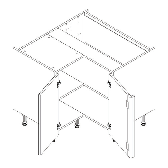
972 Corner Base (Door, Solid Top, 9 Legs) - Fitting Guide
Units Parts
82x 15mm
Screw
4x 30mm
Screws
Tools Required
Jigsaw
Drill
A minimum of two people will be needed to lift the unit.
18x Cover
9x Legs
Caps
5x Door Buffers
2x L-Brackets
Screwdriver
Mallet
9x Leg
4x Plinth
2x Space
Clips
Plug
Brackets
2x Frontal
10x Fixing
(Packed
Plates
Separately)
Clamp
1x XLSpace
6x Shelf
2x Shelf
Plug
Peg
1x Corner post
Spirit Level
Measure
Tape
Page 1
Advertisement

Subscribe to Our Youtube Channel
Related Manuals for Wren Kitchens Base Unit 972 Corner Base


Summary of Contents for Wren Kitchens Base Unit 972 Corner Base
- Page 1 E A S Y - F I T Base Unit 972 Corner Base (Door, Solid Top, 9 Legs) - Fitting Guide Units Parts 82x 15mm 18x Cover 9x Legs 9x Leg 4x Plinth 2x Space 1x XLSpace 6x Shelf 2x Shelf Screw Caps Clips...
- Page 2 Remember to take care when unpacking. Please keep your workspace clean, clear and tidy when working. This will help keep all items safe from any damages. Any un-needed cardboard or plastic should be flattened down and placed in the bin. Removing the unit, frontals, fixtures and fittings The small unit of the L-shape corner unit will...
- Page 3 Inserting the leg bases Locate the leg brackets and position, as shown in the diagram. Ensure the leg brackets are rotated so the flange covers the outer edge, as this provides support for the edge of the unit. Pay extra attention to the leg bases highlighted.
- Page 4 Notching out the side panels (when required) In order to allow for any horizontal pipework running behind the unit, some units will require the back of unit’s side to be notched out. Create a notch for the horizontal pipes at the back of the end panels using a jigsaw.
- Page 5 Drilling the pilot hole Drill a pilot hole through the back panel making sure to lightly mark the wall to indicate where the wall fixing should be placed. The hole should be located as per the diagram, in the centre and close to the top of the unit.
- Page 6 Before attaching the units together, ensure that the milano profie cutout of both units align. Securing to adjacent units Clamp together the two units, checking the front edges are level and flush. Using the screws provided, 1x30mm screw should be fixed into each corner of the carcase side.
- Page 7 Lifting the shelf into position (Small shelf) Next, rest the small shelf onto the shelf pegs and over the fixing plates. Attaching the two shelves together Lastly, join each of the fixing plates with 2x15mm screws to the small shelf by drilling upward to attach the shelves together.
- Page 8 Fixing the hinges to the frontals Insert the hinges into the top and bottom holes on the frontal. Secure the hinges by tightening 2x screws with the hinge dowels attached. These are already positioned within the hinges. Connecting the corner post Align the corner post to the frontal.
- Page 9 Adjusting the hinge To adjust the hinges, use a screwdriver as required at points 1 and 2. Point 1 -Will adjust the frontals left and right. Point 2 - Will adjust the frontals in and out. Point 3 - Will adjust the height of the frontal. Re-tighten the screw.
Need help?
Do you have a question about the Base Unit 972 Corner Base and is the answer not in the manual?
Questions and answers