2N IP Safety User Manual
Hide thumbs
Also See for IP Safety:
- Installation manual (82 pages) ,
- Configuration manual (282 pages) ,
- Installation manual (66 pages)
Table of Contents
Advertisement
Quick Links
Advertisement
Table of Contents

Related Manuals for 2N IP Safety


Summary of Contents for 2N IP Safety
- Page 1 2N IP Safety User Manual...
-
Page 2: Table Of Contents
Dynamic IP Address Setting ....................... 50 Factory Default Reset ........................ 51 IP Address Retrieval ........................51 IP Address Retrieval Using 2N Network Scanner ................. 51 IP Address Retrieval Using Hardware ..................52 IP Address Retrieval Using Speed Dial Button ................53 Dynamic/Static IP Address Switching ..................... - Page 3 Troubleshooting ..........................58 Technical Parameters ........................59 General Drawings ......................... 63 Surface Installation ........................63 Flush mounting – into plasterboard ..................... 63 General Instructions and Cautions ....................65 Directives, Laws and Regulations ....................65 Electric Waste and Used Battery Pack Handling ................67...
-
Page 4: Symbols And Terms Used
Symbols and Terms Used Symbols and Terms Used The following symbols and pictograms are used in the manual: DANGER Always abide by this information to prevent persons from injury. WARNING Always abide by this information to prevent damage to the device. CAUTION Important information for system functionality. -
Page 5: Product Description
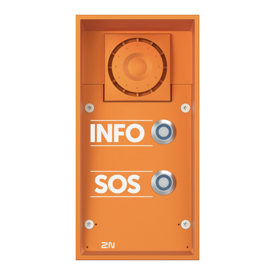
Basic Features 2N IP Safety is highly durable and a reliable IP intercom equipped with a number of useful features that are not common in devices in this category. Thanks to support for the SIP standard and compatibility with renowned manufacturers of IP PBXs and telephones, it can use all VoIP network services. -
Page 6: Product Versions
Product Description Product Versions Part No. 9158104 Axis Part No. 01353-001 2N IP Safety main unit – 1 button, 10 W loudspeaker • IP69K • 1 button • 10 W loudspeaker • Control of two electric locks • Additional switch connection option Part No. -
Page 7: Accessories
Choose the proper accessories for your particular installation needs. All 2N IP Safety units can be used without additional accessories for flush and surface installation, however, the appropriate mounting kit must be used for plasterboard or hollow brick masonry installations. - Page 8 Product Description Part No. 9152000 Axis Part No. 01356-001 Flush mounting frame – orange version Suitable for covering the device edge or flush or plasterboard installa tions. Aluminum cast. Part No. 9151001 Axis Part No. 01348-001 Flush mounting box for walls The box material is stainless steel.
-
Page 9: Extenders
Product Description Part No. 9151006 Axis Part No. 01352-001 Installation adapter (US) Part No. 9151018 Axis Part No. 01345-001 Security screws This is a safer alternative to regular screws. The screw head type is torx with pin (supplied with matching handle). Extenders... - Page 10 600 mA) or such non-critical equipment as lights (passive relay output of 30 V / 1 A for an indefinite time). It also comes with a tamper switch indicating that the 2N IP Safety front panel is open. Part No. 9159050 Axis Part No.
-
Page 11: Power Supply
Designed for external supply of electric locks. Part No. 9159052 Axis Part No. 01393-001 12 V / 1 A power supply for 2N Induction Loop The external induction loop power supply has 230 V AC input voltage and 12 V DC output voltage. -
Page 12: Licenses
Part No. 9137921 Axis Part No. 03160-001 MS Teams license • Refer to the Configuration Manual for 2N IP Intercoms, Subs. 3.2 Function Licensing details. • Please refer to the local 2N distributor for more accessories and recommendations. Other accessories... - Page 13 Product Description Part No. 9159013 Axis Part No. 02523-001 Departure button The departure button is connected to the device logic input for opening the door from inside the building. Part No. 9159012 Axis Part No. 01388-001 Magnetic door contact Set for installation on a door, enabling the status of door opening to be ascertained.
- Page 14 Product Description Part No. 9134166E Axis Part No. 01396-001 RFID chip fob EM, 125 Hz RFID chip fob, type EM4100, 125 kHz. Part No. 11202601 Axis Part No. 02787-001 RFID chip card MIFARE DESFire, 13.56 MHz RFID chip fob, type MIFARE DESFire EV3 4 K, 13.56 MHz (ISO/ IEC14443A).
- Page 15 • ST SR (SR, SRI, SRIX) • My2N • 2N PICard The device can also read the 13.56 MHz 2N PICard RFID cards. Part No. 9137424E Axis Part No. 01527-001 External secured RFID reader, 13.56 MHz + 125 kHz, NFC/HCE External secured RFID card reader connectable to a PC via a USB interface.
-
Page 16: Package Completeness Check
IP de vice. You do not have to configure anything, all you need is one 2N 2Wire unit at each end of the cable and a power supply connected to at least one of these units. - Page 17 (5 x 80) mm "intelligent" (8 x 50) mm dowels NOTE • Mounting frame is not included – it is sold separately as order no. 9152000. • Bushing set is the same as for 2N IP Safety, but bushings are already mounted.
-
Page 18: Installation
• Make sure that the depths of the dowel holes are accurate! The plugs are 50 mm long and the screws are 90 mm long. • Stainless steel screws are used for the 2N IP Safety assembly. Other screws than stainless steel ones corrode soon and may aesthetically deteriorate the surrounding environment! •... -
Page 19: Installation Tips
Installation CAUTION • When the proper installation instructions are not met, water might get in and destroy the electronics. As the device circuits are constantly under voltage water leakage causes electrochemical reaction. The manufacturer‘s warranty shall be void for products dam aged in this way! •... -
Page 20: Flush Mounting
Flush mounting – into classic masonry What you need for mounting: • 2N IP Safety • a properly cut hole as instructed in the box package (131 x 222 x 82 mm) • flush mounting box for walls (9151001, 01348-001) •... - Page 21 Flush mounting – into insulated facade What you need for mounting: • 2N IP Safety • a properly cut hole as instructed in the box package (135 x 243,5 x 85 mm) • longer screws (depending on the thermal insulation thickness) •...
- Page 22 Flush installation – in a hollow brick What you need for mounting: • 2N IP Safety • a properly cut hole as instructed in the box package (131 x 222 x 82 mm) • flush mounting box for walls (9151001, 01348-001)
- Page 23 Installation WARNING Note that the external side of the bricks gets damaged by cutting and the dowels cannot practically be fixed into the thin internal part of the bricks. Therefore, use the wall flush mounting box and follow the instructions for this box. If you use the brick flush mounting box, follow the instructions below: Make a hole using the template.
-
Page 24: Surface Installation
Do not complete mounting until you have finished electrical installation. Flush mounting – into plasterboard What you need for mounting: • 2N IP Safety • a properly cut hole as instructed in the box package (116 x 233 x 78 mm) • flush mounting box for plasterboards (9151002, 01349-001) •... -
Page 25: Electric Installation
• Make sure that the external power supply meets the power supply class 2 (PS2/LPS) . PoE Supply 2N IP Safety is compatible with the PoE 802.3af technology (Class 0, max. 12.95 W) and can be supplied directly from the LAN via compatible network elements. If your LAN does not support this technology, insert a PoE injector , between 2N IP Safety and the nearest network element. -
Page 26: Board Versions
Installation CAUTION Make sure that the wires are firmly attached to the terminal to avoid any free contact. Adapter Connection (1341481, 02520-001) The white wire at the end of the adapter carries the positive charge (+), the black wire carries the negative charge (−). - Page 27 Installation Connector Description Speaker Camera module Button 1 Reset button (PCB version 555v3 and higher) Configuration jumpers Induction loop output Connector type JST SHR-02V-S Extending module (RFID card reader or additional switch) Buttons 1 through 4 LAN connection Servicing connector Keypad module Left-hand microphone Right-hand microphone...
- Page 28 Installation Connector Description LED3 LAN connection activity 2N IP Safety – version 555v2...
- Page 29 Installation 2N IP Safety – version 555v3...
- Page 30 Installation 2N IP Safety – version 555v5...
-
Page 31: Available Switches
Installation Available switches Location Name Description Main unit RELAY1 Passive switch: • make and break contact • max. 30 V / 1 A AC/DC • only used to connect non-critical devices (e.g. lights) OUTPUT1 Active switch output: • 8 – 12 V DC depending on the power supply, max. 600 mA •... -
Page 32: Relay Terminal Wiring Diagrams
Relay Terminal Wiring Diagrams It is possible to connect a device to the 2N IP Safety relay terminals to be controlled by this relay, e.g. an electric/electromechanical door lock. The elements are designated as follows in the diagrams below:... -
Page 33: Lan Connection
Wiring diagram for opening the electric circuit of the controlled device LAN Connection 2N IP Safety is connected to the LAN by inserting a SSTP cable (category Cat-5e or higher) terminated with RJ-45 (connector X11) in the dedicated LAN connector on the device. As the device is equipped with the Auto-MDIX function, you can use either the straight or crossed cable version. -
Page 34: Grounding
Overvoltage Protection The 2N device cables have to be protected against atmospheric overvoltage caused by external causes (lightning, e.g.). A surge can damage a device installed outside/inside the building if the wires are unprotec ted. - Page 35 Installation Examples of Overvoltage Protection Installation Overvoltage protection installation diagram for a device installed on the building facade and cables outside the building...
- Page 36 Installation Overvoltage protection installation diagram for a device installed on the building facade and cables inside the building...
-
Page 37: Main And Extending Modules
Therefore, update the device firmware after connecting the modules. Update firmware via the web configuration interface in System > Maintenance. 2N IP Safety can be interconnected with the following modules: • Additional Switch •... -
Page 38: Specification
Installation Compatibility This extending module is intended for mounting into the 2N IP Safety main unit and is compatible with the main unit Part No. 915110xxxxx. CAUTION If the Additional Switch is installed, it is not possible to install the Internal RFID Card Reader. -
Page 39: Installation
Installation Installation Turn off the device. Remove the front panel from the device. According to your model: If you are mounting the switch into a two-nameplate model, demount the button PCB (1) and remove the right-hand bottom spacer (there are four PCB fitting spacers altogether). If you are mounting the switch into a keypad model, take the keypad out of the holder. - Page 40 Installation Put the switch board (4) in the motherboard connector. Make sure that the screw hole is directly above the spacer. According to your model: If you are mounting the switch into a two-nameplate model, fit the switch board with the enclosed 10.5 mm spacer (3) and reinstall the button PCB (1).
- Page 41 Installation Connection Version 5...
-
Page 42: Security Relay
Version 4 and lower Security Relay The Security Relay (9159010, 01386-001) is used for enhancing security between 2N IP Safety and the connected electric lock. The Security Relay significantly enhances security of the connected electric lock by preventing unlocking due to device tampering. - Page 43 The Security Relay is designed with holes for surface anchoring. It is recommended that a screw of the diameter of 3 mm with a lens head of the diameter of 6 mm is used. Using a countersunk head may cause irreversible damage to the plastic cover! 2N IP Safety Door lock Departure button...
-
Page 44: Status Signaling
• to the passive output in series with the external power supply The Security Relay also supports the Departure button connected to the ‘PB’ and ‘– 2N IP intercom’ terminals. Once the Departure button is pressed, the output is activated for 5 seconds. - Page 45 B connector. Connect the special cable to the intercom and connect the power supply to the mains. You can place the mated A and B connectors into the 2N device cover. The connectors help you connect stripped cables. Open the connector by pushing a thin screwdriver onto the white spots at its front and close the connector by sliding the movable part through a side gap.
-
Page 46: Grounding
• 0 V – green Connector A Connector B Connecting cable 2N intercom Power supply Grounding To increase the static electricity resistance, you need a cable of the minimum cross-section of 4 mm Connect the cable to the terminal in the bottom part of the device as shown in the figure below. The terminal is included in the delivery. - Page 47 • Properly installed device is waterproof. An incorrectly made installation may compromise the device waterproofness. Water infiltration may damage the electronic part. • Stainless steel screws are used for the 2N IP Safety assembly. Other screws than stain less steel ones corrode soon and may aesthetically deteriorate the surrounding environ...
-
Page 48: Brief Guidelines
Device Configuration Interface Access 2N IP Safety is configured via the web configuration interface. You have to know the device IP address or the device domain name. Make sure that the device is connected to the local IP network and powered. -
Page 49: Configuration Via Hardware
Brief Guidelines It is recommended that a password is used that is difficult to break. It is not recommended that names, places or things, especially those closely related to the user, are used in the password. For increased password security, it is recommended that: •... -
Page 50: Dynamic Ip Address Setting
Brief Guidelines Press and hold the RESET button. Wait until the red and green LEDs go on simultaneously on the device and the acoustic signal can be heard (approx. 15–35 s). Wait until the red LED goes off and the acoustic signal can be heard (approx. -
Page 51: Factory Default Reset
• Use the freely accessible 2N Network Scanner. • Use the Speed Dial button. IP Address Retrieval Using 2N Network Scanner The application helps you find the IP addresses of all the 2N devices in the LAN. Download 2N Network Scanner from the 2N.com website. -
Page 52: Ip Address Retrieval Using Hardware
In that case, click Refresh to find the device again and check whether multicast is enabled in your network. • Double click the selected row in the 2N Network Scanner list to access the device web interface easily. • To change the device IP address, select Config and enter the required static IP address or activate DHCP. -
Page 53: Ip Address Retrieval Using Speed Dial Button
IP Address Retrieval Using Speed Dial Button Take the following steps to retrieve the 2N IP Safety IP address: Connect the device to the power supply (if connected, disconnect and reconnect it). Wait for the second sound signal. -
Page 54: Device Restart
Maintenance > System using Restart . Firmware Update We recommend that the firmware is also updated during the 2N IP Safety installation. Refer to 2N.com the latest FW version. Update firmware via the web configuration interface in System > Maintenance, refer to the device Configura... -
Page 55: Factory Default Reset
Brief Guidelines Factory Default Reset Press and hold the RESET button. Wait until the red and green LEDs go on simultaneously on the device and the acoustic signal can be heard (approx. 15–35 s). Wait until the red LED goes off and the acoustic signal can be heard (approx. -
Page 56: Call Connection
Enter the calling destination address into the destination field to which the call is to be routed. Complete the target IP address or SIP URI in the format “ user_name@host” (e.g.: “johana@2.255.4.255” or “johana@calls.2N.com”). For local calls, fill in the called 2N device ID as specified in the Local Calls... - Page 57 Speed dial buttons. Make sure that the call transmitting service is enabled on the called 2N device to make a successful call. • Each user can be assigned up to 3 phone numbers. In case the first user fails to answer, the call is forwarded to the next number.
-
Page 58: Troubleshooting
Troubleshooting Troubleshooting Refer to https://www.2n.com/faqs for the most frequently solved problems. -
Page 59: Technical Parameters
Technical Parameters Technical Parameters Power Supply Types: IEEE PoE 802.3af (Class 0, max. 12.95 W) External supply 12 V / 1 A DC Signaling protocol UDP, TCP, TLS Buttons Button design Industrial waterproof, vandal resistant, stainless steel, blue backlit pushbutton Button count 1 (na zakázku 2) Numeric Keypad... - Page 60 Technical Parameters Audio Microphone 2 integrované Amplifier 10 W (class D) Speaker 10 W Sound pressure level (SPL max) 78,5 dB (1 W model, pro 1 kHz ve vzdálenosti 1 m); 94 dB ± 3 % (10 W model, pro 1 kHz ve vzdálenosti 1 m) Volume Control Adjustable with automatic adaptive mode Full duplex...
- Page 61 Technical Parameters Interface 10/100BASE-TX with Auto-MDIX, RJ-45 Recommended cabling Cat-5e or higher Supported protocols SIP2.0, DHCP opt. 66, SMTP, 802.1x, RTSP, RTP, TFTP, HTTP, HTTPS, Syslog, ONVIF Passive switch (relay) spínací a rozpínací kontakt (NO/NC), max. 30 V / 1 A AC/DC...
- Page 62 Technical Parameters Mechanical Parameters Cover Robust aluminum cast product Color: • RAL 2004 orange Body material • Black version: • Material - Zamak 410 - Zn95Al4Cu1 • Surface treatment – PUR Wet coating 15-25 μm, RAL 9005 Jet black, inner side - passivated zinc Weight (depending on con...
-
Page 63: General Drawings
Technical Parameters General Drawings Surface Installation Flush mounting – into plasterboard... - Page 64 Technical Parameters Flush mounting – into classic masonry...
-
Page 65: General Instructions And Cautions
The manufacturer also assumes no responsibility for additional costs incurred by the consumer as a result of making calls to increased tariff lines. Directives, Laws and Regulations 2N IP Safety conforms to the following directives and regulations: • 2012/19/EU on waste electrical and electronic equipment... -
Page 66: Industry Canada
General Instructions and Cautions • 2014/30/EU for electromagnetic compatibility • 2014/35/EU for electrical equipment designed for use within certain voltage limits • 2011/65/EU on the restriction of the use of certain hazardous substances in electrical and electronic equipment Industry Canada This Class B digital apparatus complies with Canadian ICES-003/NMB-003. -
Page 67: Electric Waste And Used Battery Pack Handling
General Instructions and Cautions 本製品は電気通信事業者(移動通信会社、固定通信会社、インターネットプロバイダ等)の通信回線(公衆 無線 LAN を含む)に直接接続することができません。本製品をインターネットに接続する場合は、必ずル ータ等を経由し接続してください。 Electric Waste and Used Battery Pack Handling Do not place used electric devices and battery packs into municipal waste containers. An undue disposal thereof might impair the environment! Deliver your expired household electric appliances and battery packs removed from them to dedicated dumpsites or containers or give them back to the dealer or manufacturer for environmental-friendly dispos... - Page 68 2N IP Safety – User Manual © 2N Telekomunikace a. s., 2025 2N.com...
Need help?
Do you have a question about the IP Safety and is the answer not in the manual?
Questions and answers