
Subscribe to Our Youtube Channel
Related Manuals for ADLINK Technology ECAT IO Series


Summary of Contents for ADLINK Technology ECAT IO Series
- Page 1 ECAT IO Series EtherCAT IO Slave Modules User’s Manual Manual Rev.: Revision Date: Sept. 5, 2023 Part No: 50M-27013-1000...
-
Page 2: Revision History
Revision History Revision Release Date Description of Change(s) 2023-09-05 Initial release Revision History... -
Page 3: Preface
ECAT IO Series Preface Copyright © 2023 ADLINK Technology Inc. This document contains proprietary information protected by copy- right. All rights are reserved. No part of this manual may be repro- duced by any mechanical, electronic, or other means in any form without prior written permission of the manufacturer. - Page 4 California Proposition 65 Warning WARNING: This product can expose you to chemicals including acrylamide, arsenic, benzene, cadmium, Tris(1,3-dichloro-2-propyl) phosphate (TDCPP), 1,4- Dioxane, formaldehyde, lead, DEHP, styrene, DINP, BBP, PVC, and vinyl materials, which are known to the State of California to cause cancer, and acrylamide, benzene, cadmium, lead, mercury, phthalates, toluene, DEHP, DIDP, DnHP, DBP, BBP, PVC, and vinyl materials, which are known to the State of California to cause...
-
Page 5: Table Of Contents
Motion Creator Pro 2 (MCP2) ........6 Accessories ................. 7 1.5.1 Features ................ 7 2 Getting Started ..............9 Unpacking the ECAT IO Series ........... 9 Mechanical Dimensions ............. 10 Connectors and Indicators ..........13 2.3.1 LED Indicators............. 14 2.3.2 EtherCAT Ports ............ - Page 6 2.4.2 Installation Procedures..........21 2.4.3 Troubleshooting ............22 2.4.4 Software Driver Installation ......... 22 3 Signal Connections ............23 Isolated Digital Input ............23 Isolated Digital Output............23 4 Process Data Objects ............25 ECAT-DI32................. 25 ECAT-DO32............... 25 DI16DO16 ................26 A Appendix: Object Dictionary..........27 ECAT-DI32 Object Dictionary ..........
-
Page 7: List Of Tables
ECAT IO Series List of Tables Table 2-1: Slave ID Switch Settings .......... 15 Table 2-2: ECAT-DI32-M-N Pin Assignment ......18 Table 2-3: ECAT-DO32-M-N Pin Assignment ......19 Table 2-4: ECAT-DI16DO16-M-NN Pin Assignment ....20 Table A-1: ECAT-DI32 Object Dictionary ........27 Table A-2: ECAT-DO32 Object Dictionary ......... - Page 8 This page intentionally left blank. viii List of Tables...
-
Page 9: List Of Figures
ECAT IO Series List of Figures Figure 1-1: Functional Diagram............2 Figure 2-1: Top View................ 10 Figure 2-2: Front View..............10 Figure 2-3: Right View..............11 Figure 2-4: Bottom View..............12 Figure 2-5: Connector and Indicator Layout........13 Figure 2-6: Slave ID Address Switches..........15 Figure 2-7: 40-Pin Signal Connector Pin Definitions...... - Page 10 This page intentionally left blank. List of Figures...
-
Page 11: Introduction
EN 61000-6 for heavy industrial EMC protection, as well as receiving an emissions certificate. As the ECAT IO Series must be used with an EtherCAT master, we recommend using ADLINK products, such as the PCIe-833x series and SuperCAT, for the best performance, easiest integra- tion and potential for function expansion. -
Page 12: Functional Diagram
Wiring Cable: The cables connecting the EtherCAT master and slave I/O modules are standard 100 Base/TX with RJ45 connec- tors, which are identical with commercial Ethernet cables. 1.1.1 Functional Diagram 16-Position rotary switch 16-Position rotary switch MDI0 RJ45 MDI1 RJ45 G, G, G, R Power, Run, EEP_DONE, Error LED *4... -
Page 13: Features
ECAT IO Series 1.2 Features Supports up to 100μs EtherCAT cycle time with DC mode Status holding mode when disconnected Connects up to 256 modules Easy maintenance by hot-plugging Flexible terminal block design for alternate wiring ... -
Page 14: Specifications
1.3 Specifications Model ECAT-DI32-M-N ECAT-DO32-M-N ECAT-D16DO16-M-NN Digital Input Channels Input Type Wet (Sink/Source) Wet (Sink/Source) On: 11.4V DC (max.) On: 11.4V DC (max.) Operational Off: 14.3V DC (min.) Off: 14.3V DC (min.) Voltage (24V DC) On: 12.6V DC (min.) On: 12.6V DC (min.) Off: 9.8V DC (max.) Off: 9.8V DC (max.) Isolation... - Page 15 ECAT IO Series Model ECAT-DI32-M-N ECAT-DO32-M-N ECAT-D16DO16-M-NN Communicati on Cycle 100 μs Time Data Ethernet/EtherCAT Cable Transfer (Min. CAT 5), Shielded Medium Distributed Clocks Status Holding Software Configurable Mode Power, Run, Error, EEP, Power, Run, Error, EEP, Power, Run, Error, EEP,...
-
Page 16: Supported Software
1.4.2 APS Functions The ECAT IO Series is fully compliant with the APS (Automation Product Software) function library, independent of programming languages and operating systems (OS). A complete detailed list- ing of functions can be found in the APS Function Library User Manual. -
Page 17: Accessories
ECAT IO Series 1.5 Accessories Available terminal bases include: ECAT-TB32-M-DIN: Terminal board exclusive for ECAT IO M type. ECAT-TB32-U-DIN: Terminal board exclusive for ECAT IO DB type. 1.5.1 Features 32-channel ECAT IO Terminal Base Field I/O wiring connection for ECAT I/O modules ... - Page 18 This page intentionally left blank.
-
Page 19: Getting Started
This chapter describes how to install and connect to an ECAT IO Series module, its hardware settings, and related signals. 2.1 Unpacking the ECAT IO Series Ensure that the following items are included in the package. If any items are missing, contact your sales representative for assistance. -
Page 20: Mechanical Dimensions
2.2 Mechanical Dimensions All dimensions in millimeters (mm) unless noted. 97.40 Figure 2-1: Top View Figure 2-2: Front View... -
Page 21: Figure 2-3: Right View
ECAT IO Series 21.50 Figure 2-3: Right View... -
Page 22: Figure 2-4: Bottom View
M2.5 Figure 2-4: Bottom View... -
Page 23: Connectors And Indicators
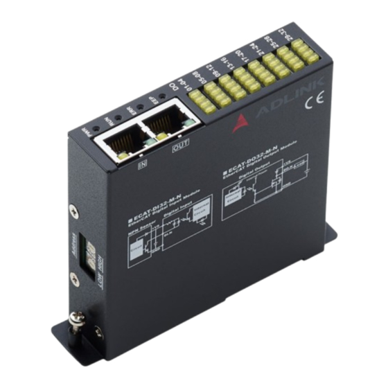
ECAT IO Series 2.3 Connectors and Indicators 2x Slave ID Address Switches 2x RJ45 EtherCAT Ports 4x System LED Indicators 32x IO LED Indicators 40-Pin Signal Connector Figure 2-5: Connector and Indicator Layout... -
Page 24: Led Indicators
2.3.1 LED Indicators LED indicator states follow the EtherCAT specifications. Function Color Status Off: Power off Green On: Power on Off: Initialization Blinking: Pre-Operational Green Single Flash: Safe Operational On: Operational Flickering: Bootstrap Off: No Error Blinking: Invalid Configuration Single Flash: Local Error Double Flash: Watchdog Timeout Off: the EEPROM is not successfully loaded by ESC Green... -
Page 25: Slave Id Address Switches Settings
ECAT IO Series 2.3.3 Slave ID Address Switches Settings The slave ID address switches are used to set the ECAT IO mod- ule slave ID addresses. Index values can be set from 0 to 255. The default slave ID switch setting is 0. - Page 26 LOW HIGH LOW HIGH LOW HIGH LOW HIGH...
- Page 27 ECAT IO Series LOW HIGH LOW HIGH LOW HIGH LOW HIGH...
-
Page 28: 40-Pin Signal Connector
2.3.4 40-Pin Signal Connector The 40-pin signal connector provides input and output signals for ECAT IO series modules. Figure 2-7: 40-Pin Signal Connector Pin Definitions Table 2-2: ECAT-DI32-M-N Pin Assignment Signal Description Signal Description E24V External power supply E24V External power supply... -
Page 29: Table 2-3: Ecat-Do32-M-N Pin Assignment
ECAT IO Series Table 2-3: ECAT-DO32-M-N Pin Assignment Signal Description Signal Description E24V External power supply E24V External power supply IO_PWR I/O power supply IO_PWR I/O power supply DICOM DICOM IO_GND I/O ground EGND External power ground Digital output Digital output... -
Page 30: Table 2-4: Ecat-Di16Do16-M-Nn Pin Assignment
Table 2-4: ECAT-DI16DO16-M-NN Pin Assignment Signal Description Signal Description E24V External power supply E24V External power supply IO_PWR I/O power supply IO_PWR I/O power supply Mechanical input / Mechanical input / DICOM DICOM general input general input IO_GND I/O ground EGND External power ground Digital input... -
Page 31: Hardware And Software Driver Installation
ECAT IO Series 2.4 Hardware and Software Driver Installation 2.4.1 Hardware Configuration The ECAT IO Series is composed of two parts: an EtherCAT IO module and a terminal board. 2.4.2 Installation Procedures 1. Read through this manual and setup the jumper and I/O signals according to your application. -
Page 32: Troubleshooting
2.4.3 Troubleshooting If the computer cannot power on normally or the motion control system operates abnormally after system installation, follow the steps described below for troubleshooting. If the problem persists, consult your dealer for technical service. Problem Correction Motion Creator Pro 2™ does not Ensure .NET framework v3.5 or later is launch after driver installation. -
Page 33: Signal Connections
ECAT IO Series Signal Connections Signal connections of all I/Os are described in this chapter. Refer to the contents of this chapter before wiring any cables between the ECAT IO Series module and any sensor devices. 3.1 Isolated Digital Input D3.3V 4.7K... - Page 34 This page intentionally left blank.
-
Page 35: Process Data Objects
ECAT IO Series Process Data Objects Process Data Objects are a fundamental concept in the EtherCAT protocol and are used to exchange real-time process data between EtherCAT devices. The definition of ECAT IO series modules is as follows. 4.1 ECAT-DI32 Name/... -
Page 36: Di16Do16
4.3 DI16DO16 Name/ Data Index Unit Range Access Description Index Description Mapping Type Digital input 0x6002 1 DI16 TxPDO 0~FFFF U16 16-ch data Digital output 0x7002 1 DO16 RxPDO 0~FFFF U16 16-ch data 1. Retain option for digital output while network disconnected. -
Page 37: Appendix A Object Dictionary
ECAT IO Series Appendix A Object Dictionary An Object Dictionary is a structured collection of data objects that define the behavior, parameters, and communication characteris- tics of each ECAT IO module. A.1 ECAT-DI32 Object Dictionary Name / Index Access Default Value... -
Page 38: Ecat-Do32 Object Dictionary
A.2 ECAT-DO32 Object Dictionary Name / Index Access Default Value Index Description 0x1000 Device type 0x00820191 0x1001 Error Register 0x00 0x1008 Device Name ECAT-DO32-M-N 0x1009 Hardware version RO 0x100A 0 Software version 2023021401 0x1018 identify 0x1018 Vender ID 0x0000144A 0x1018 Product Code 0x00015100 0x1018... -
Page 39: Appendix B Twincat
ECAT IO Series Appendix B TwinCAT TwinCAT® is a software system from Beckhoff that provides an integrated development environment (IDE) for programming and configuring industrial automation and control systems. This appendix will show how to connect an ECAT IO via TwinCAT and operate the IO functions. -
Page 40: Activate Ecat Io Devices
B.2 Activate ECAT IO Devices Follow the steps below to activate ECAT IO devices. 1. Create a project and right-click I/O>Devices, then select Scan to initiate a scan for EtherCAT devices. - Page 41 ECAT IO Series All network interface cards will be listed in the popup win- dow. If slaves are connected to the network interface card and have been identified by TwinCAT, the will be checked. Click OK. 2. Click Yes to activate the slave.
- Page 42 3. ECAT IO will be listed as a slave device of the EtherCAT master and the Run status LED will be green. This indi- cates that the user can begin operating the device.
-
Page 43: Operation
ECAT IO Series B.3 Operation In this example, there is an ECAT-DO32 module in the topology with 32 digital output channels which are respectively controlled by bits 0-31. A bit value of "0" means it is turned off, and a bit value of "1"... - Page 44 This page intentionally left blank.
-
Page 45: Important Safety Instructions
ECAT IO Series Important Safety Instructions For user safety, please read and follow all instructions, Warnings, Cautions, and Notes marked in this manual and on the associated device before handling/operating the device, to avoid injury or damage. Read these safety instructions carefully. - Page 46 A Lithium-type battery may be provided for uninterrupted backup or emergency power. Risk of explosion if battery is replaced with one of an incorrect type; please dispose of used batteries appropriately. CAUTION: This equipment is not suitable for use in locations where ...
-
Page 47: Consignes De Sécurité Importante
ECAT IO Series Consignes de Sécurité Importante S'il vous plaît prêter attention stricte à tous les avertissements et mises en garde figurant sur l'appareil, pour éviter des blessures ou des dommages. Lisez attentivement ces consignes de sécurité. Conservez le manuel de l'utilisateur pour pouvoir le con- ... - Page 48 Si l'appareil ne doit pas être utilisé pendant de longues péri- odes, éteignez-le et débranchez-le de sa source d'alimenta- tion N'essayez jamais de réparer l'appareil, qui ne doit être réparé que par un personnel technique qualifié à l'aide d'outils appro- priés Une batterie de type Lithium peut être fournie pour une ali- ...
- Page 49 ECAT IO Series RISQUE DE BRÛLURES Partie chaude! Ne touchez pas cette surface, cela pourrait entraîner des blessures. Pour éviter tout danger, laissez la surface refroidir avant de la toucher. Consignes de Sécurité Importante...
- Page 50 This page intentionally left blank. Consignes de Sécurité Importante...
-
Page 51: Getting Service
6450 Via Del Oro, San Jose, CA 95119-1208, USA Tel: +1-408-360-0200 Toll Free: +1-800-966-5200 (USA only) Fax: +1-408-600-1189 Email: info@adlinktech.com ADLINK Technology (China) Co., Ltd. 300 Fang Chun Rd., Zhangjiang Hi-Tech Park Pudong New Area, Shanghai, 201203 China Tel: +86-21-5132-8988 Fax: +86-21-5132-3588 Email: market@adlinktech.com ADLINK Technology GmbH Hans-Thoma-Straße 11...
Need help?
Do you have a question about the ECAT IO Series and is the answer not in the manual?
Questions and answers