Advertisement
6000 Series Discrete Input/Output Modules
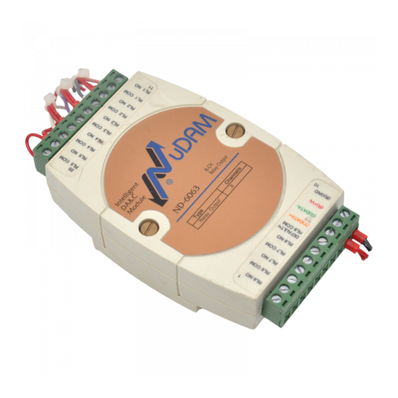
-6063 Relay Output and Isolated Input Module
1. Introduction
NuDAM-6063 provides eight form A relay output channels. It
can control high power devices without external circuits. The
isolation guarantees the industrial safety.
Features
4 channels relay output
programmable power on output state
programmable out polarity setting
programmable host watchdog timer for host failure
protection
internal watchdog timer for device failure protection
easy programming by software
easy installation and wiring
Specifications
Interface:
RS-485, 2 wires
Speed (bps): 600, 1200, 2400, 4800, 9600, 19.2k,
38.4k, 57.6k, 115.2k
Relay Output:
Channel number: 8
Output type: form A
Contact rating:
AC 0.5A/125V
DC 1A/30V, 0.3A/110V
ON/OFF time interval: 3ms
8
Expected life: 10
(at 180 cpm)
Insulation resistance: 1000 M minimum (at
500VDC)
Storage Temperature Range: -25 to 80 C
Operating Temperature Range: -10 to 70 C
Power Requirement: +10V to +30V
Unregulated
DC
with against power reversal
Power Consumption: 0.7W
Case: ABS with captive mounting hardware
CE Class A Conformity
The Optimal Choice for Harsh Environment
2. Pin Assignment
8-CH Isolated
Relay Output
ND-6063
Channels
Type
Relay Output
8
Pin Definitions
Pin #
Signal Name Description
1
RL6 NO
Relay 6, normal open
2
RL6 COM
Relay 6, common
3
RL7 NO
Relay 7, normal open
4
RL7 COM
Relay 7, common
5
RL8 NO
Relay 8, normal open
6
DEFAULT*/
Initial state setting
RL8 COM
Relay 8, common
7
(Y)DATA+
RS-485 signal, positive
8
(G)DATA-
RS-485 signal, negative
9
(R)+VS
Power supply, +10V ~ +30Vdc
10
(B)GND
Ground
11
RL1 NO
Relay 1, normal open
12
RL1 COM
Relay 1, common
13
RL2 NO
Relay 2, normal open
14
RL2 COM
Relay 2, common
15
RL3 NO
Relay 3, normal open
16
RL3 COM
Relay 3, common
17
RL4 NO
Relay 4, normal open
18
RL4 COM
Relay 4, common
19
RL5 NO
Relay 5, normal open
20
RL5 COM
Relay 5, common
*The module is in DEFAULT mode when DEFAULT* pin
connected to GND while applying power on the module.
*Do not apply any power signal to DEFAULT* pin, just left
it open or connected it to GND.
3. Application Wiring
Form A Relay Output
External Power Source
+Vs
RL n
Power
NO
Loading
From
Micro
Processor
COM
External power ground
4.Jumper Setting
Init* Mode
JP2
1
2
3
DEFAULT
INIT*
Digital
Output
Mode (Default Setting)
JP2
1
2
3
RL8. COM
INIT*
Part No: 50-12026-200
5. Installation
Equipment for Installation
A existing RS-485 network
NuDAM modules
DC Power supply (+10V~+30V)
Wires for power, communication and I/O signal
Installation Procedure
1.
Configure every single NuDAM module under the
administration utility.
2.
The baud rate setting and calibration procedure
must be done under the DEFAULT* mode.
3.
The baud rate and check-sum status must be identity
with the application network. The address ID must
not be conflict with other modules on the network.
4.
Plug the new module to the existing network.
5.
Use the NuDAM administration utility to check the
entire network.
Advertisement
Table of Contents

Related Manuals for ADLINK Technology NuDAM-6063


Summary of Contents for ADLINK Technology NuDAM-6063
- Page 1 1. Introduction 2. Pin Assignment 3. Application Wiring 5. Installation NuDAM-6063 provides eight form A relay output channels. It Form A Relay Output Equipment for Installation can control high power devices without external circuits. The isolation guarantees the industrial safety.
- Page 2 I/O Polarity Setting ~(Addr)CP(State) Functional Command watchdog timer, safe values, and the programmable leading Copyright 2001 ADLINK TECHNOLOGY INC. Read Digital Output Status Read Polarity Setting ~(Addr)CR $(Addr)6 code. All the commands used in the NuDAM analog input...
Need help?
Do you have a question about the NuDAM-6063 and is the answer not in the manual?
Questions and answers