
Subscribe to Our Youtube Channel
Related Manuals for ADLINK Technology EGX-MXM-T1000


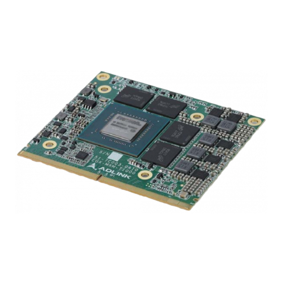
Summary of Contents for ADLINK Technology EGX-MXM-T1000
- Page 1 EGX-MXM-T1000 NVIDIA Turing™ TU117 Quadro® T1000 Embedded Graphics Module User’s Manual Manual Rev.: July 15, 2020 Revision Date: 50-1Z327-1000 Part No: Leading EDGE COMPUTING...
- Page 2 Leading EDGE COMPUTING Revision History Revision Release Date Description of Change(s) 2020-07-15 Initial release Revision History...
-
Page 3: Preface
EGX-MXM-T1000 Preface Copyright © 2020 ADLINK Technology Inc. This document contains proprietary information protected by copy- right. All rights are reserved. No part of this manual may be repro- duced by any mechanical, electronic, or other means in any form without prior written permission of the manufacturer. - Page 4 Leading EDGE COMPUTING California Proposition 65 Warning WARNING: This product can expose you to chemicals including acrylamide, arsenic, benzene, cadmium, Tris(1,3-dichloro-2-propyl) phosphate (TDCPP), 1,4- Dioxane, formaldehyde, lead, DEHP, styrene, DINP, BBP, PVC, and vinyl materials, which are known to the State of California to cause cancer, and acrylamide, benzene, cadmium, lead, mercury, phthalates, toluene, DEHP, DIDP, DnHP, DBP, BBP, PVC, and vinyl materials, which are known to the State of...
-
Page 5: Table Of Contents
EGX-MXM-T1000 Table of Contents Revision History..............ii Preface ..................iii List of Tables................. vii List of Figures ................ ix 1 Introduction ................ 1 Overview................1 Features................1 Specifications............... 2 1.3.1 Graphics Module ............2 1.3.2 Display Support and Options........3 1.3.3... - Page 6 Leading EDGE COMPUTING Important Safety Instructions..........21 Getting Service ..............23 Table of Contents...
-
Page 7: List Of Tables
EGX-MXM-T1000 List of Tables Table 1-1: Graphics Module Display Options ......3 Table 1-2: NVIDIA Link Display Types ........3 Table 1-3: MXM Connector Pin Definitions........8 Table 1-4: Thermal Policy............13 List of Tables... - Page 8 Leading EDGE COMPUTING This page intentionally left blank. viii List of Tables...
-
Page 9: List Of Figures
Figure 1-1: EGX-MXM-T1000 Functional Block Diagram ..... 4 Figure 1-2: EGX-MXM-T1000 Dimensions ........5 Figure 1-3: EGX-MXM-T1000 Layout - Top and Side Views ..6 Figure 1-4: EGX-MXM-T1000 Layout - Bottom View....7 Figure 1-5: MXM Connector............7 Figure 2-1: Power Sequencing ........... - Page 10 Leading EDGE COMPUTING This page intentionally left blank. List of Figures...
-
Page 11: Introduction
NVIDIA Quadro® T1000 GPU based on the advanced NVIDIA Turing™ TU117 architecture in MXM 3.1 Type A form factor. The EGX-MXM-T1000 brings a new level of performance to visual graphics and computing applications, fully integrating hardware acceleration for both graphics and computing code, enabling hard- ware acceleration for a wider class of software applications than ever before. -
Page 12: Specifications
Leading EDGE COMPUTING 1.3 Specifications 1.3.1 Graphics Module Graphics Core Architecture NVIDIA® Turing™ TU117 Quadro® T1000 4x DisplayPort 1.4 Display Outputs Max resolution 7680 x4320 @60Hz DSC MST: 1920x1080 for 4 ports Signal Interface MXM 3.1, PCI Express Gen3 x16 support GPGPU Computing 896 CUDA cores, 2.6 TFLOPS SP Peak CUDA Support... -
Page 13: Display Support And Options
CUDA Toolkit 8.0 and higher CUDA Compute version 6.1 and higher OpenCL™ 1.2 DirectX® 12 OpenGL 4.5 Vulcan 1.0 1.3.4 Graphics Options The EGX-MXM-T1000 supports 4xDisplayPort by default, with dis- play options as shown below. DP_A DP_B DP_C DP_D MXM port Link E... -
Page 14: Functional Block Diagram
DP_A IFPE Channel B GDDR6 x32 memory down DP1.4 DP_B IFPA GDDR6 x32 DP1.4 DP_C IFPC memory down DP1.4 DP_D IFPB VBIOS NVIDIA Quadro® LED*2 T1000 GPU Power Management (PWR_EN PWR_GOOD WAKE#) JTAG Figure 1-1: EGX-MXM-T1000 Functional Block Diagram Introduction... -
Page 15: Mechanical Layout
EGX-MXM-T1000 1.5 Mechanical Layout All dimensions shown are in mm NOTE: NOTE: Figure 1-2: EGX-MXM-T1000 Dimensions Introduction... -
Page 16: Figure 1-3: Egx-Mxm-T1000 Layout - Top And Side Views
4 pcs Top Side: OD=6.0mm; ID=3.2mm Bottom Side: OD=7.0mm; ID=3.2mm A-Section 1.25 Scale 2 : 1 1.25 0.50 0.50 0.50 0.50 E-Section D-Section Scale 2 : 1 Scale 2 : 1 Figure 1-3: EGX-MXM-T1000 Layout - Top and Side Views Introduction... -
Page 17: Figure 1-4: Egx-Mxm-T1000 Layout - Bottom View
EGX-MXM-T1000 39.76 34.74 28.75 2x4.82 129x0.35 2.35 1.85 Bottom Side Figure 1-4: EGX-MXM-T1000 Layout - Bottom View (R G5 X G6) Pin 125 Pin 281 Pin E1 Pin 133 Pin E3 Pin E2 Pin 134 Pin 124 Pin E4 Figure 1-5: MXM Connector... -
Page 18: Mxm Connector Pin Definitions
Leading EDGE COMPUTING 1.6 MXM Connector Pin Definitions Primary Side (bottom side) Secondary Side (top side) Signal PU/PD Signal PU/PD PWR_SRC PWR_SRC PRSNT_R# 0ohm PD RSVD PWR_GOOD PWR_EN 27MHZ_REF RSVD RSVD 100K PU to PWR_LEVEL 3.3V 100K PU to RSVD TH_OVERT# 3.3V 100K PU to... - Page 19 EGX-MXM-T1000 Primary Side (bottom side) Secondary Side (top side) Signal PU/PD Signal PU/PD PEX_TX15# PEX_RX15# PEX_TX15 PEX_RX15 PEX_TX14# PEX_RX14# PEX_TX14 PEX_RX14 PEX_TX13# PEX_RX13# PEX_TX13 PEX_RX13 PEX_TX12# PEX_RX12# PEX_TX12 PEX_RX12 PEX_TX11# PEX_RX11# PEX_TX11 PEX_RX11 PEX_TX10# PEX_RX10# PEX_TX10 PEX_RX10 PEX_TX9# PEX_RX9# PEX_TX9...
- Page 20 Leading EDGE COMPUTING Primary Side (bottom side) Secondary Side (top side) Signal PU/PD Signal PU/PD PEX_TX5# PEX_RX5# PEX_TX5 PEX_RX5 PEX_TX4# PEX_RX4# PEX_TX4 PEX_RX4 PEX_TX3# PEX_RX3# PEX_TX3 PEX_RX3 PEX_RX2# PEX_TX2# PEX_RX2 PEX_TX2 PEX_RX1# PEX_TX1# PEX_RX1 PEX_TX1 PEX_RX0# PEX_TX0# PEX_RX0 PEX_TX0 PEX_REFCLK# 154 PEX_CLK_REQ# PEX_REFCLK PEX_RST#...
- Page 21 EGX-MXM-T1000 Primary Side (bottom side) Secondary Side (top side) Signal PU/PD Signal PU/PD RSVD RSVD RSVD RSVD RSVD RSVD RSVD RSVD RSVD RSVD RSVD RSVD RSVD RSVD RSVD RSVD RSVD RSVD RSVD RSVD RSVD RSVD DP_C_L0# RSVD DP_C_L0 RSVD DP_C_L1#...
- Page 22 Leading EDGE COMPUTING Primary Side (bottom side) Secondary Side (top side) Signal PU/PD Signal PU/PD RSVD RSVD DP_D_AUX# RSVD DP_D_AUX RSVD DP_C_HPD PD 100K RSVD DP_D_HPD PD 100K RSVD RSVD RSVD RSVD RSVD RSVD DP_B_L0# RSVD DP_B_L0 RSVD DP_B_L1# DP_A_L0# DP_B_L1 DP_A_L0 DP_B_L2#...
-
Page 23: Thermal Policy
Retain the shipping carton and packing materials for inspection. Obtain authorization from your dealer before returning any product to ADLINK. Ensure that the fol- lowing items are included in the package. EGX-MXM-T1000 embedded graphics module Introduction... - Page 24 Leading EDGE COMPUTING This page intentionally left blank. Introduction...
-
Page 25: System Requirements
EGX-MXM-T1000 System Requirements 2.1 Power Sequencing For initial power on, or to Resume from S3 and S4, this sequence must be followed. PV-PE PE-PG PV-PE PE-PG Figure 2-1: Power Sequencing 2.2 Module Power Up and Down Issuing the PWR_EN signal powers the MXM module down, and the system designer can decide whether to keep the module input power when the MXM module is powered down. -
Page 26: Reset Requirements
Leading EDGE COMPUTING MODULE INPUT POWER PWR_EN MODULE INTERNAL POWER PWR_GOOD Figure 2-2: Module Power Down 2.3 Reset Requirements PVPERL PERST-PG FAIL PERST-CLK MODULE INPUT POWER PVPERL PERST-CLK PWR_EN PERST-PG FAIL PWR_GOOD PEX_REFCLK PEX_RST# Figure 2-3: Reset Sequencing System Requirements... -
Page 27: Dual Mode Displayport Implementation
EGX-MXM-T1000 2.4 Dual Mode DisplayPort Implementation The EGX-MXM-T1000 supports four dual mode DisplayPorts by default. HDMI is supported via dongle (see “Display Support and Options” on page 3.). The system requires a switch circuit to determine whether the AUX or DDC signal is output from the MXM module, and AC coupling capacitors should be placed on the sys- tem board. -
Page 28: Dvi/Hdmi On Displayport Interface
Leading EDGE COMPUTING 2.5 DVI/HDMI on DisplayPort Interface DVI and HDMI connectors can both be implemented through the DisplayPort interface. Circuits required on the system board are as shown. 499Ω with 1% pulldown resistors to the ground on the DP lanes must placed on the DVI/HDMI connector side of the AC cou- pling, gated by a MOSFET to limit leakage. -
Page 29: Certifications & Agencies
EGX-MXM-T1000 2.7 Certifications & Agencies Windows Hardware Quality Lab (WHQL) certified for Windows 10 EU Reduction of Hazardous Substances (EU-RoHS) Conformité Européenne (CE) Federal Communications Commission (FCC) System Requirements... - Page 30 Leading EDGE COMPUTING This page intentionally left blank. System Requirements...
- Page 31 EGX-MXM-T1000 Important Safety Instructions For user safety, please read and follow all instructions, Warnings, Cautions, and Notes marked in this manual and on the associated device before handling/operating the device, to avoid injury or damage. S'il vous plaît prêter attention stricte à tous les avertissements et mises en garde figurant sur l'appareil , pour éviter des blessures...
- Page 32 Leading EDGE COMPUTING Never attempt to repair the device, which should only be serviced by qualified technical personnel using suitable tools The device must be serviced by authorized technicians when: The power cord or plug is damaged Liquid has entered the device interior The device has been exposed to high humidity and/or moisture The device is not functioning or does not function...
- Page 33 San Jose, CA 95138, USA Tel: +1-408-360-0200 Toll Free: +1-800-966-5200 (USA only) Fax: +1-408-360-0222 Email: info@adlinktech.com ADLINK Technology (China) Co., Ltd. 300 Fang Chun Rd., Zhangjiang Hi-Tech Park Pudong New Area, Shanghai, 201203 China Tel: +86-21-5132-8988 Fax: +86-21-5132-3588 Email: market@adlinktech.com...
Need help?
Do you have a question about the EGX-MXM-T1000 and is the answer not in the manual?
Questions and answers