
Related Manuals for ADLINK Technology PXI-7901


Summary of Contents for ADLINK Technology PXI-7901
- Page 1 PXI-7901 16-ch General-Purpose SPDT Relay Module User’s Manual Manual Rev.: Rev. 1.1 Date: February 7, 2020 Part Number: 50-17010-1010...
- Page 2 Trademarks NuDAQ™, NuIPC™, NuDAM™, NuPRO™ are registered trademarks of ADLINK Technology Inc. Other product names mentioned herein are used for identification purposes only and may be trademarks and/or registered trademarks of their respective companies.
- Page 3 Environmental Responsibility ADLINK is committed to fulfill its social responsibility to global environmental preservation through compliance with the European Union's Restriction of Hazardous Substances (RoHS) directive and Waste Electrical and Electronic Equipment (WEEE) directive. Environmental protection is a top priority for ADLINK. We have enforced measures to ensure that our products, manufacturing processes, components, and raw materials have as little impact on the environment as possible.
- Page 4 Getting Service Customer Satisfaction is top priority for ADLINK Technology Inc. If you need any help or service, please contact us at Ask an Expert: http://askanexpert.adlinktech.com. ADLINK Technology, Inc. Web Site http://www.adlinktech.com Sales & Service Service@adlinktech.com Telephone +886-2-8226-5877 +886-2-8226-5717 Address 9F, No.
-
Page 5: Table Of Contents
2.4 Installing the switch module into a PXI Platform ....6 Chapter 3 Signal Connection ............ 9 3.1 PXI-7901 Topology ..............9 3.2 PXI-7901 Pin assignment & Description ......9 3.3 TB-6201 Terminal Board ..........10 Chapter 4 Operation Theorem ..........11 4.1 Hardware Block Diagram .......... -
Page 6: How To Use This Manual
How to Use This Manual This User Manual is designed to assist users in the installation of the ADLINK PXI-7901, 16-ch General Purpose SPDT Relay PXI Switch module. Chapter 1 Introduction Gives an outline and overview of ADLINK switch modules’... -
Page 7: Chapter 1 Introduction
ATE. Relays of PXI-7901 can be updated by either direct-update mode or auto-scan mode. The latter mode supports scanlist of 1k-sample for deterministic scanning. -
Page 8: Applications
1.2 Applications • Industrial ON/OFF control • External high power relay driving and signal switching • Laboratory automation • Industrial automation • Switch contact status sensing • Limit switch monitoring • Cooperating with other modules such as A/D and D/A peripherals to implement a data acquisition and control system 1.3 Specifications Relay Output... -
Page 9: Software Support
Safety Functions • Emergency shutdown • Logic level: 3.3 V/TTL (5V tolerant) • Active with logic low (for AUX2/SHDNn pin) • Emergency shutdown sources: AUX2/SHDNn, PXI star trigger input, PXI trigger bus • Watchdog timer • Base clock available: 10MHz, fixed •... - Page 10 This page intentionally left blank. 4 • Introduction...
-
Page 11: Chapter 2 Installation
ADLINK switch module. 2.1 Contents The package consists of the following items in addition to the User Manual: • PXI-7901, 16-ch General Purpose SPDT Relay module • This User’s Guide • ADLINK Software CD •... -
Page 12: Mechanical Drawing
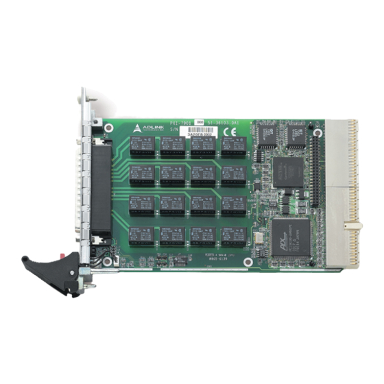
Note: Do not apply power to the module if it has been damaged. You are now ready to install the PXI-7901 2.3 Mechanical Drawing Figure 1: ADLINK Switch Module ADLINK switch module is packaged in a Eurocard form factor compliant with PXI Specifications measuring 160 mm in length and 100 mm in height (not including connectors). - Page 13 Figure 2: Installing the switch module into a PXI platform Installation • 7...
- Page 14 This page intentionally left blank. 8 • Installation...
-
Page 15: Chapter 3 Signal Connection
Signal Connection 3.1 PXI-7901 Topology The PXI-7901 has 16 independent SPDT Relays onboard. Each relay has three terminals, NC (normally closed), NO (normally opened), and COM (common). When a relay is in its reset (de-energized) state, the NC connects to COM;... -
Page 16: Tb-6201 Terminal Board
3.3 TB-6201 Terminal Board The TB-6201 is a screw terminal board with D-sub 62-pin female connector. The terminal board can attach to PXI-7901 directly, or through ADLINK custom- made high-capacity 62-pin D-sub cable. The pin description is described in Table 2. -
Page 17: Chapter 4 Operation Theorem
Operation Theorem 4.1 Hardware Block Diagram The ADLINK PXI Switch Module features an onboard FPGA for relay switching control, trigger control, scanlist storage and sequencing. The PXI triggering and synchronization functions, such as Star Trigger and Trigger Bus are also supported. -
Page 18: Operation Mode
If relay contact bouncing is of a concern, users would need to insert software delay. ADLINK recommends the debounce time to be at least 8ms on PXI-7901. Auto-scan The ADLINK PXI switch module features onboard memory to store user specified scanlist of up to 1024-entry. - Page 19 Figure 4 illustrates the available signal sources for the Trigger In signal. Signal names in the solid-line box represent the external (physical) signal on connectors, and signals in the dotted-line box represents switch module’s internal signal. Software Trigger TRG_IN Trigger In Signal Trigger Bus AUX[7…0] Star Trigger In...
- Page 20 Handshaking protocol Figures 6 and 7 depict the relationship between Trigger In, Scanner Advanced, and relay pattern in handshaking mode. In Figure 7 the Scanner Advanced is set to pulsating mode. Trigger In Scanner Advanced attern Pattern #2 Pattern #3 Relay Status Operation Start Figure 6: Handshaking operation (Scanner Advanced set in pulsating mode)
- Page 21 8 ms for PXI-7901. T is the user specified scan delay time in the scanlist entry, indicating the time between the relay being debounced and the exact moment that a measurement device takes a new measurement.
-
Page 22: Trigger Bus
Start auto-scan by sending scan start command to the switch module. ADLINK PXI Switch module Scanner Advanced Output (S_ADV) External Trigger Input Trigger Input (Trig In) (TRG_IN) Agilent 33401A Wiring 6-1/2 DMM Measurement Complete (VM Comp) Figure 8: Signal Connection between Switch Module and Agilent DMM For more information on scanlist configuration, scan mode setup, start, and stop functions of the auto-scanning process, please refer to the software programming users’... - Page 23 Figure 9 illustrates the available signal destinations for Trigger Bus[7..0]. Signal names in the solid-line boxes represent the external (physical) signals on connectors while signals in the dotted-line boxes represent the switch module’s internal signal. Software Trigger Trigger In Signal Scanner Adv.
-
Page 24: Auxiliary Digital I/O
4.5 Auxiliary Digital I/O The eight auxiliary digital I/O lines on ADLINK Switch Modules provide versatility to users’ control applications. Each digital I/O line can be input, output or tri-stated. When in output mode, users can still read back the actual logic- level on the I/O line. -
Page 25: Hot-Swap
Note: Microsoft Windows 2000 does not natively support hot-swap however, PXI-7901 can be hot-swapped by manual control via an additional hot-swap driver. For the hot-swap driver on Windows 2000 and other operating systems such as Linux, VxWorks, etc., please contact ADLINK for more information. -
Page 26: Watchdog Timer
Star Trigger In Figure 11: Available trigger sources for emergency shutdown The default relay pattern for emergency shutdown is All-Off on PXI-7901; users can change the pattern by Windows API. Upon receiving the emergency shutdown trigger, the Switch Module enters shutdown mode, and the relay pattern is switched to the preset state. - Page 27 Int. WDTimer Trigger Bus WDT Overflow Star Trigger In Figure 12:.Available trigger sources for watchdog timer overflow The watchdog timer overflow interval can be programmed through Windows API. After enabling the watchdog timer, users must periodically reset the timer by software command.
- Page 28 This page intentionally left blank. 22 • Operation Theorem...
-
Page 29: Warranty Policy
Warranty Policy Thank you for choosing ADLINK. To understand your rights and enjoy all the after-sales services we offer, please read the following carefully: Before using ADLINK’s products please read the user manual and follow the instructions exactly. When sending in damaged products for repair, please attach an RMA application form.
Need help?
Do you have a question about the PXI-7901 and is the answer not in the manual?
Questions and answers