
Related Manuals for ADLINK Technology Express-HR


Summary of Contents for ADLINK Technology Express-HR
- Page 1 Express-HR User’s Manual Manual Revision: 2.00 Revision Date: June 11, 2012 Part Number: 50-1J036-1000...
- Page 2 Revision History Release Date Change 2.00 June 11, 2012 Initial release Page 2 Express-HR User’s Manual...
-
Page 3: Table Of Contents
Signal Descriptions ......................18 Onboard Fan Connector....................26 6 Module Configuration ..................... 27 Digital Display Interface (DDI) ................... 27 PCI Express x16 Configuration ..................27 Express-HR User’s Manual Page 3 Express-IA533 User’s Manual Express-IA533 User’s Manual Express-HR User’s Manual Page 3... - Page 4 10 BIOS Checkpoints, Beep Codes ................65 10.1 Status Code Ranges ......................66 10.2 Standard Status Codes ..................... 66 10.3 OEM-Reserved Status Code Ranges ................72 Important Safety Instructions ..................73 Getting Service ......................74 Page 4 Express-HR User’s Manual...
-
Page 5: Preface
Preface Copyright 2012 ADLINK Technology, Inc. This document contains proprietary information protected by copyright. All rights are reserved. No part of this manual may be reproduced by any mechanical, electronic, or other means in any form without prior written permission of the manufacturer. - Page 6 Information to prevent minor physical injury, component damage, data loss, and/or program corruption when trying to complete a task. Information to prevent serious physical injury, component damage, data loss, and/or program corruption when trying to complete a specific task. Page 6 Express-HR User’s Manual...
-
Page 7: Introduction
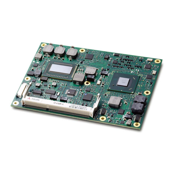
1 Introduction 1.1 Description The Express-HR is a COM Express® COM.0 R2.0 Type 6 module supporting the 64-bit Intel® Core™ i7/i5 processor with CPU, memory controller, and graphics processor on the same chip. Based on the latest Mobile Intel® QM67 Express chipset, the Express-HR is specifically designed for customers who need high-level processing and graphics performance in a long product life solution. -
Page 8: Specifications
Purpose PCI Express (2 x8 or 1 x8 with 2 x4) - see 6.2 PCI Express x16 Configuration On Chipset: 8 PCI Express x1: 0/1/2/3/4/5/6 are free, 7 is occupied by GbE LAN LPC bus for optional connections to SIO, UART, etc. LPC bus, SMBus (system), I C (user) Page 8 Express-HR User’s Manual... -
Page 9: Video
2.4 Audio Chipset: Integrated in Intel® PCH QM67 Audio Codec: on Express-BASE6 (ALC888) 2.5 LAN Chipset: Intel® Gigabit LAN PHY WG82579LM Interface: 10/100/1000 Mbps Ethernet Express-HR User’s Manual Page 9 Express-IA533 User’s Manual Express-IA533 User’s Manual Express-HR User’s Manual Page 9... -
Page 10: Multi I/O
Type: TPM 1.2 2.9 Power Specifications Input Power: AT mode (12 V +/- 5%) and ATX mode (12 V and 5 Vsb +/- 5%) Power States: supporting S0, S1, S3, S4, S5 Smart Battery Support: yes Page 10 Express-HR User’s Manual... -
Page 11: Power Consumption
S1 (standby powered on) 0.73 A N.S. 8.76 W S3 (suspend to RAM) 0.48 A 2.4 W S5 (soft off) 0.37 A 1.85W Express-HR User’s Manual Page 11 Express-IA533 User’s Manual Express-IA533 User’s Manual Express-HR User’s Manual Page 11 Page 11 Page 11... -
Page 12: Operating Systems
Form Factor : PICMG COM.0 R2, COM Express Basic form factor ™ Type : PICMG COM.0 R2, COM Express Type 6 pinout ™ Dimensions: 95 x 125 mm Standard Operating Temperature: 0°C to 60°C Relative Humidity: up to 90% at 60°C Page 12 Express-HR User’s Manual... -
Page 13: Function Diagram
Debug SLB9635 header LPC bus 4x GPI SPI 1 GPIO Monitor BIOS 4x GP0 PCA9535 ADT7490 SMBus SPI 2 BIOS Express-HR User’s Manual Page 13 Express-IA533 User’s Manual Express-IA533 User’s Manual Express-HR User’s Manual Page 13 Page 13 Page 13... -
Page 14: Mechanical Dimensions
4 Mechanical Dimensions tolerances ± 0.05 mm Other tolerances ± 0.2 mm Page 14 Express-HR User’s Manual... -
Page 15: Pinout And Signal Descriptions
5 Pinout and Signal Descriptions 5.1 COM Express Type 6 compatible pinout ® All signals on AB and CD connectors of the Express-HR comply with pinouts and conventions used in the original “PICMG COM.0 R2.0: COM Express Module Base Specification”. -
Page 16: Pin Definitions
USB3- DDI3_PAIR1+ DDI2_PAIR1+ USB2+ USB3+ DDI3_PAIR1- DDI2_PAIR1- USB_2_3_OC# USB_0_1_OC# DDI3_HPD DDI2_HPD USB0- USB1- RSVD RSVD USB0+ USB1+ DDI3_PAIR2+ DDI2_PAIR2+ VCC_RTC EXCD1_PERST# DDI3_PAIR2- DDI2_PAIR2- EXCD0_PERST# EXCD1_CPPE# RSVD RSVD EXCD0_CPPE# SYS_RESET# DDI3_PAIR3+ DDI2_PAIR3+ LPC_SERIRQ CB_RESET# DDI3_PAIR3- DDI2_PAIR3- Page 16 Express-HR User’s Manual... - Page 17 GND (FIXED) C110 GND (FIXED) D110 GND (FIXED) XXX Strikethrough pin names indicates that the signal is not supported on this module. Express-HR User’s Manual Page 17 Express-IA533 User’s Manual Express-IA533 User’s Manual Express-HR User’s Manual Page 17 Page 17...
-
Page 18: Signal Descriptions
PCI Express 5 Transmit + O - DP PCIE5_TX+ PCIE5_TX- PCI Express 5 Transmit - O - DP General Purpose Input 0 I-3.3 PU 10k 3.3Vsb GPI0 PCI Express 4 Transmit + O - DP PCIE4_TX+ Page 18 Express-HR User’s Manual... - Page 19 Power 12V VCC_12V A106 Power 12V VCC_12V A107 Power 12V VCC_12V A108 Power 12V VCC_12V A109 Power 12V VCC_12V A110 Ground Express-HR User’s Manual Page 19 Express-IA533 User’s Manual Express-IA533 User’s Manual Express-HR User’s Manual Page 19 Page 19 Page 19...
- Page 20 PCI Express 5 Recieve + I - DP PCIE5_RX+ PCIE5_RX- PCI Express 5 Receive - I - DP General Purpose Output 1 O-3.3 PU 10k 3.3Vsb GPO1 PCI Express 4 Recieve + I - DP PCIE4_RX+ Page 20 Express-HR User’s Manual...
- Page 21 Power 12V VCC_12V B106 VCC_12V Power 12V B107 Power 12V VCC_12V B108 VCC_12V Power 12V B109 Power 12V VCC_12V B110 Ground Express-HR User’s Manual Page 21 Express-IA533 User’s Manual Express-IA533 User’s Manual Express-HR User’s Manual Page 21 Page 21 Page 21...
- Page 22 DP3_LANE3- / TMDS3_CLK- Ground I - DP PEG_RX0+ PCIe 0 Recieve + PEG_RX0- PCIe 0 Recieve - I - DP not connected TYPE0# Module type ID pin 0 I - DP PEG_RX1+ PCIe 1 Recieve + Page 22 Express-HR User’s Manual...
- Page 23 Power 12V VCC_12V C106 VCC_12V Power 12V C107 Power 12V VCC_12V C108 Power 12V VCC_12V C109 Power 12V VCC_12V C110 Ground Express-HR User’s Manual Page 23 Express-IA533 User’s Manual Express-IA533 User’s Manual Express-HR User’s Manual Page 23 Page 23 Page 23...
- Page 24 O - DP DDI2_PAIR3- DP2_LANE3- / TMDS2_CLK- Ground O - DP PEG_TX0+ PCIe 0 Transmit + PEG_TX0- O - DP PCIe 0 Transmit - I-3.3 PEG_LANE_RV# PCIe Lane Reversal O - DP PEG_TX1+ PCIe 1 Transmit + Page 24 Express-HR User’s Manual...
- Page 25 Power 12V VCC_12V D106 VCC_12V Power 12V D107 Power 12V VCC_12V D108 VCC_12V Power 12V D109 Power 12V VCC_12V D110 Ground Express-HR User’s Manual Page 25 Express-IA533 User’s Manual Express-IA533 User’s Manual Express-HR User’s Manual Page 25 Page 25 Page 25...
-
Page 26: Onboard Fan Connector
Pull Up Resistor Pull Down Resistor Not Connected / Reserved 5.5 Onboard Fan Connector The Express-HR has an onboard fan connector (FAN1: 3-pin 1.25 mm Wafer) on the underside of the board, next to the SODIMM socket. FAN1: 12V Fan Power... -
Page 27: Module Configuration
6 Module Configuration 6.1 Digital Display Interface (DDI) The Express-HR’s three DDI ports support the following output types: DDI1: DP / HDMI / DVI / SDVO DDI2: DP / HDMI / DVI DDI3: DP / HDMI / DVI / eDP To set the output type, go to the BIOS setup utility and navigate to the following screens: Chipset >... -
Page 28: Embedded Functions
The AIDI library includes a demo program to demonstrate the library’s functionallity. Watchdog Timer The Express-HR implements a Watchdog timer that can be used to automatically detect software execution problems or system hangs and reset the board if necessary. The Watchdog timer consists of a counter that counts down from an initial value to zero. -
Page 29: Gpio
The COM Express Type 6 standard assigns the following pins for either GPI or GPO Signal Type # AIDI ID (bit) Remark GPI0 Express-HR can configure this pin for GPI and GPO GPI1 Express-HR can configure this pin for GPI and GPO GPI2 Express-HR can configure this pin for GPI andGPO... -
Page 30: Hardware Monitoring
On the Express-HR the following monitored values can be read from the module: CPU temperature, system temperature, Vcore, 1.8V, 5V, 3.3V and 12V. -
Page 31: System Resources
A0000 - BFFFF 128 KB Video Buffer & SMM space 0 KB - 640 KB 00000 - 9FFFF 640 KB DOS Area Express-HR User’s Manual Page 31 Express-IA533 User’s Manual Express-IA533 User’s Manual Express-HR User’s Manual Page 31 Page 31... -
Page 32: Direct Memory Access Channels
SATA controller or PCI 376 and 3F6 COM2 COM1 4D0 and 4D1 Interrupt controller Reset Control register (8 bit I/O) 4700 E000-E03F Graphics E040-E05F SMbus E060-E07F 82579Lan E080-E137 SATA E140-E147 Remote Keyboard and Text (KT)(When iAMT support) Page 32 Express-HR User’s Manual... -
Page 33: Interrupt Request (Irq) Lines
IRQ9 via SERIRQ Available Available PS/2 Mouse IRQ12 via SERIRQ Math Processor SATA Primary IRQ14 via SERIRQ SATA Secondary IRQ15 via SERIRQ Express-HR User’s Manual Page 33 Express-IA533 User’s Manual Express-IA533 User’s Manual Express-HR User’s Manual Page 33 Page 33 Page 33... - Page 34 SATA Secondary IRQ15 via SERIRQ PCIE Root Port 0 PCIE Root Port 0 EHCI Controller 0, EHCI Controller 0, HD Graphics HD Graphics SATA controller 0 SATA controller 1 PCH 82579LM Lan controller EHCI Controller 1 Page 34 Express-HR User’s Manual...
-
Page 35: Pci Configuration Space Map
0FFh Internal PCIE Port #4 0FFh Internal PCIE Port #5 0FFh Internal PCIE Port #6 0FFh Internal PCIE Port #7 Express-HR User’s Manual Page 35 Express-IA533 User’s Manual Express-IA533 User’s Manual Express-HR User’s Manual Page 35 Page 35 Page 35... -
Page 36: Pci Interrupt Routing Map
INT C INT D INT A INT C INT D INT A INT B INT C INT D INT A INT B INT D INT A INT B INT C INT D INT A INT B INT C Page 36 Express-HR User’s Manual... -
Page 37: Bios Setup Utility
9 BIOS Setup Utility The following chapter describes basic navigation for the UEFI BIOS setup utility for the ADLINK Express-HR COM Express module. The following content is for BIOS ver. A1.0. 9.1 Starting the BIOS To enter the setup screen, follow these steps: 1. -
Page 38: Uefi Bios Setup Utility
Press the <Enter> key to discard changes and exit. You can also use the<Arrow> key to select Cancel and then press the <Enter> key to abort this function and return to the previous screen. Page 38 Express-HR User’s Manual... -
Page 39: Main Setup
9.3 Main Setup System and Board Information Express-HR User’s Manual Page 39 Express-IA533 User’s Manual Express-IA533 User’s Manual Express-HR User’s Manual Page 39 Page 39 Page 39... -
Page 40: Advanced Setup
Launch Storage OpROM Enabled - Set this value to allow the option for Legacy Mass Storage Devices with option ROM. Disabled - Set this value to prevent the option for Legacy Mass Storage Devices with option Page 40 Express-HR User’s Manual... - Page 41 When AT mode is set, Windows will not turn off power when performing a shutdown. Some operating systems (e.g. Windows XP) will show the "It is safe to turn off your computer" message. When ATX mode is set, the operating system will shut down power normally. Express-HR User’s Manual Page 41 Express-IA533 User’s Manual Express-IA533 User’s Manual...
- Page 42 9.4.2 Trusted Computing 9.4.3 RTC Wake Settings ACPI RTC Wake Sets the ACPI RTC Wake time. Page 42 Express-HR User’s Manual...
- Page 43 Adjacent Cache Line P This feature is used to enable optimal use of sequential memory access for performance purposes. Disable this setting for applications requiring high use of random memory access. Express-HR User’s Manual Page 43 Express-IA533 User’s Manual Express-IA533 User’s Manual Express-HR User’s Manual...
- Page 44 Options are Enabled/Disabled. 9.4.5 SATA Configuration SATA Controller Enable or disable the SATA Controller. SATA Mode The SATA can be configured as a legacy IDE, RAID and AHCI mode. Page 44 Express-HR User’s Manual...
- Page 45 This option allows the user to configure Intel Trusted Execution Technology. 9.4.7 PCH-FW Configuration This option allows the user to view the information of the ME Firmware. Express-HR User’s Manual Page 45 Express-IA533 User’s Manual Express-IA533 User’s Manual Express-HR User’s Manual...
- Page 46 This option allows the user to configure Intel Anti-Theft Technology. Intel Anti-Theft Tech Enables or disables Intel Anti-Theft technology, and sets the maximum number of recovery attempts. Enter Intel AT Suspend Enables or disables Intel AT Suspend Mode. Page 46 Express-HR User’s Manual...
- Page 47 This option allows the user to enable/disable Intel AMT. 9.4.10 USB Configuration Legacy USB Support Enables and disables Legacy USB support. Disabling this option will keep USB devices available only for EFI applications. Express-HR User’s Manual Page 47 Express-IA533 User’s Manual Express-IA533 User’s Manual Express-HR User’s Manual...
- Page 48 Allows the user to set the connected USB devices to emulate as a specific type. Option: Auto, Floppy, Force FDD, Hard Disk, CD-ROM. 9.4.11 ADT 7490 H/W Monitor This option allows the user to view and configure the parameters of the ADT7490 hardware monitor. Page 48 Express-HR User’s Manual...
- Page 49 Smart Fan Mode Configuration Fan1 controls the Express-HR onboard FAN1 connector (next to SODIMM socket). Fan2 controls the FAN3 connector on the Express-BASE6 Reference Carrier Board. Fan1/2 Smart Fan Mode Allows the user to set the Fan1/2 Smart Fan mode.
- Page 50 Serial Port Set parameters of serial port 1/2. Options are Enabled/Disabled. Change Settings This option specifies the base I/O port address and Interrupt Request address of serial port 1/2. Configuration options: Auto, 3F8, 3E8, 2F8, 2E8. Page 50 Express-HR User’s Manual...
- Page 51 Options are Enabled/Disabled. Console Redirection Settings The settings specify how the host computer and the remote computer will exchange data. Both computers should have the same or compatible settings. Express-HR User’s Manual Page 51 Express-IA533 User’s Manual Express-IA533 User’s Manual Express-HR User’s Manual...
- Page 52 None, Hardware and Software. Recorder Mode Allows the user to enable/disable the Recorder Mode. Resolution 100x31 Allows the user to enable/disable Resolution 100x31. Legacy OS Redirection Allows the user to set Legacy OS Redirection. Options: 80x24, 80x25. Page 52 Express-HR User’s Manual...
- Page 53 This option allows the user to view and configure the settings for processor power management. EIST Allows the user to enable/disable Enhanced Intel SpeedStep Technology. Turbo Mode Allows the user to enable/disable Turbo Mode of the CPU. Express-HR User’s Manual Page 53 Express-IA533 User’s Manual Express-IA533 User’s Manual Express-HR User’s Manual Page 53...
-
Page 54: Chipset Configuration
9.5 Chipset Configuration Select the Chipset tab from the setup screen to enter the Chipset Configuration screen. 9.5.1 System Agent (SA) Configuration VT-d This option allows the user to enable/disable Intel Virtualization Technology for Directed I/O. Page 54 Express-HR User’s Manual... - Page 55 96M, 128M, 160M, 192M, 224M, 256M, 288M, 320M, 352M. DVMT Total Gfx Mem Allows the user to set the the total amount of DVMT graphics memory. Options: 128MB, 256MB, Max. Express-HR User’s Manual Page 55 Express-IA533 User’s Manual Express-IA533 User’s Manual Express-HR User’s Manual...
- Page 56 Allows the user to set the backlight control duty cycle of PWM. Options: 0%, 20%, 40%, 60%, 80%, 100%.GTT LVDS Backlight Co GTT LVDS Backlight Inverter Allows the user to set the PWM inverter state. Options: PWM Inverted, PWM Normal. Page 56 Express-HR User’s Manual...
- Page 57 NB PCIe Configuration Memory Configuration Express-HR User’s Manual Page 57 Express-IA533 User’s Manual Express-IA533 User’s Manual Express-HR User’s Manual Page 57 Page 57 Page 57...
- Page 58 Set this value to power off/on the system depending on the last system power state while AC power is restored. BC I2C Speed Control Options: 100 kHz, 200 kHz, 400 kHz Sleep & LID Button Enables or disables support of the sleep & LID button signal from GPI of the COM Express connector. Page 58 Express-HR User’s Manual...
- Page 59 Allows the user to set the link width of PCIe ports 0-3. Options: Four x1 Ports, One x4 Port. PCI Express Root Port 1~7 Allow the user to enable/disable the PCI Express Root Ports 1~7. Express-HR User’s Manual Page 59 Express-IA533 User’s Manual Express-IA533 User’s Manual...
-
Page 60: Boot Setup
Quiet Boot Disabled - Set this value to allow the computer system to display the POST messages. Enabled - Set this value to allow the computer system to display the OEM logo. Page 60 Express-HR User’s Manual... - Page 61 Then you may use the arrow keys to select the desired device, then press <+>, <-> or <PageUp>, <PageDown> key to move it up/down in the priority list. Only the first device in each device group will be available for selection in Boot Option. Express-HR User’s Manual Page 61 Express-IA533 User’s Manual Express-IA533 User’s Manual...
-
Page 62: Security Setup
Use this option to set a password for administrators with full control of the BIOS setup utility. User Password Use this option to set a password for users with limited access to the BIOS setup utility. Page 62 Express-HR User’s Manual... -
Page 63: Save & Exit
Reset the system after saving the changes. Discard Changes and Reset Reset system setup without saving any changes. Save Options Save changes made so far to any of the setup options. Express-HR User’s Manual Page 63 Express-IA533 User’s Manual Express-IA533 User’s Manual Express-HR User’s Manual... - Page 64 Restore the User Defaults to all the setup options. Boot Override Use the up/down arrow keys to highlight a boot device or "Launch EFI Shell" to immediately exit the BIOS Setup and boot from the selected device. Page 64 Express-HR User’s Manual...
-
Page 65: Bios Checkpoints, Beep Codes
Keep in mind that not all computers using AMIBIOS enable this feature. In most cases, a checkpoint card is the best tool for viewing AMIBIOS checkpoints. Express-HR User’s Manual Page 65 Express-IA533 User’s Manual Express-IA533 User’s Manual Express-HR User’s Manual... -
Page 66: Status Code Ranges
South Bridge initialization after microcode loading OEM initialization after microcode loading Cache initialization SEC Error Codes 0xC – 0xD Reserved for future AMI SEC error codes Microcode not found Microcode not loaded SEC Beep Codes None. Page 66 Express-HR User’s Manual... - Page 67 Post-Memory South Bridge initialization (South Bridge module specific) 0x3E Post-Memory South Bridge initialization (South Bridge module specific) 0x3F-0x4E OEM post memory initialization codes 0x4F DXE IPL is started Express-HR User’s Manual Page 67 Express-IA533 User’s Manual Express-IA533 User’s Manual Express-HR User’s Manual Page 67 Page 67...
- Page 68 0xF5-0xF7 Reserved for future AMI progress codes Recovery Error Codes 0xF8 Recovery PPI is not available 0xF9 Recovery capsule is not found 0xFA Invalid recovery capsule 0xFB – 0xFF Reserved for future AMI error codes Page 68 Express-HR User’s Manual...
- Page 69 Reserved for future AMI DXE codes 0x80 – 0x8F OEM DXE initialization codes 0x90 Boot Device Selection (BDS) phase is started 0x91 Driver connecting is started Express-HR User’s Manual Page 69 Express-IA533 User’s Manual Express-IA533 User’s Manual Express-HR User’s Manual Page 69 Page 69...
- Page 70 0xB4 USB hot plug 0xB5 PCI bus hot plug 0xB6 Clean-up of NVRAM 0xB7 Configuration Reset (reset of NVRAM settings) 0xB8 – 0xBF Reserved for future AMI codes 0xC0 – 0xCF OEM BDS initialization codes Page 70 Express-HR User’s Manual...
- Page 71 0xAC System has transitioned into ACPI mode. Interrupt controller is in PIC mode. 0xAA System has transitioned into ACPI mode. Interrupt controller is in APIC mode. Express-HR User’s Manual Page 71 Express-IA533 User’s Manual Express-IA533 User’s Manual Express-HR User’s Manual...
-
Page 72: Oem-Reserved Status Code Ranges
OEM SEC initialization after microcode loading 0x1D – 0x2A OEM pre-memory initialization codes 0x3F – 0x4E OEM PEI post memory initialization codes 0x80 – 0x8F OEM DXE initialization codes 0xC0 – 0xCF OEM BDS initialization codes Page 72 Express-HR User’s Manual... -
Page 73: Important Safety Instructions
- It is not functioning or does not function according to the user’s manual; - It has been dropped and/or damaged; and/or, - It has an obvious sign of breakage. Express-HR User’s Manual Page 73 Express-IA533 User’s Manual Express-IA533 User’s Manual Express-HR User’s Manual... -
Page 74: Getting Service
5215 Hellyer Avenue, #110, San Jose, CA 95138, USA Tel: +1-408-360-0200 Toll Free: +1-800-966-5200 (USA only) Fax: +1-408-360-0222 Email: info@adlinktech.com ADLINK Technology (China) Co., Ltd. Address: (201203) 300 Fang Chun Rd., Zhangjiang Hi-Tech Park, Pudong New Area, Shanghai, 201203 China Tel: +86-21-5132-8988 Fax:... - Page 75 84 Genting Lane #07-02A, Cityneon Design Centre, Singapore 349584 Tel: +65-6844-2261 Fax: +65-6844-2263 Email: singapore@adlinktech.com ADLINK Technology Singapore Pte. Ltd. (Indian Liaison Office) Address: 1st Floor, #50-56 (Between 16th/17th Cross) Margosa Plaza, Margosa Main Road, Malleswaram, Bangalore-560055, India Tel: +91-80-65605817, +91-80-42246107 Fax: +91-80-23464606 Email: india@adlinktech.com...
Need help?
Do you have a question about the Express-HR and is the answer not in the manual?
Questions and answers