
Subscribe to Our Youtube Channel
Related Manuals for MSA PrimaX IR+


Summary of Contents for MSA PrimaX IR+
- Page 1 Operating Manual PrimaX® IR+ Gas Detector Order No.: 10246567/00 Print Spec: 10000005196 (EO) CR:800000065206 MSAsafety.com...
- Page 2 Otherwise, it could fail to perform as designed, and persons who rely on this device could sustain serious injury or death. The warranties made by MSA with respect to the product are voided if the product is not installed and used in accordance with the instructions in this manual.
-
Page 3: Table Of Contents
Contents Safety Regulations Correct Use Liability Information Safety and Precautionary Measures to be Adopted MSA Permanent Instrument Warranty Description User Interface Package Contents Installation Mechanical Installation Electrical Installation Remote Controller and Menu Sequence Remote Controller (sold separately) Menu Item Start-up and Calibration Remote Controller and Menu Sequence 5.1.1 Initial Start-up... -
Page 4: Safety Regulations
Product liability claims, warranties also as guarantees made by MSA with respect to the product are voided, if it is not used, serviced or maintained in accordance with the instructions in this manual. -
Page 5: Safety And Precautionary Measures To Be Adopted
Failure to do so may seriously impair device performance. Repair or alteration of the device, beyond the scope of these maintenance instructions or by anyone other than an authorized MSA service provider, could cause the product to fail to perform as designed. - Page 6 1 Safety Regulations THIS WARRANTY IS IN LIEU OF ALL OTHER WARRANTIES, EXPRESSED, -IMPLIED OR STATUTORY, AND IS STRICTLY LIMITED TO THE TERMS HEREOF. SELLER SPECIFICALLY DISCLAIMS ANY WARRANTY OF - MERCHANT ABILITY OR OF FITNESS FOR A PARTICULAR PURPOSE.
-
Page 7: Description
2 Description Description The safety function of the device is designed to monitor the environment combustible gas concentration at the installed location and alert the user to potentially dangerous levels of hydrocarbon gas: • When the hydrocarbon gas concentration ≥ 25% LEL (±3% LEL), the first alarm relay (NC) shall be closed and the 4-20 mA output signal is 8 - 12 mA •... -
Page 8: Package Contents
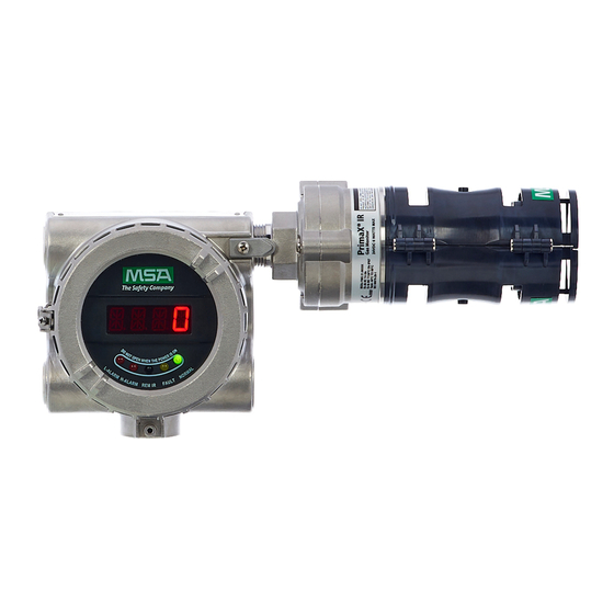
2 Description Figure 1 Device LED and Display Display Remote controller IR LED Warning LED 5 Fault LED Alarm LED Normal status LED Package Contents The device will be delivered with the following items in the shipping carton: • PrimaX IR+ Gas Detector or PrimaX IR+ Display Housing and PrimaX IR Sensor or PrimaX IR+ Display Housing (Aluminum or 316 Stainless Steel) and PrimaX IR Sensor (316 Stainless Steel) •... - Page 9 2 Description Accessories available for the PrimaX IR+ Gas Monitor include: • Optional calibration cap for calibration operations • Optional tether strap for environmental guard • Optional IR-Control remote controller For complete list of accessories see chapter 8 Ordering Information. The device will be labeled with the information shown below: •...
-
Page 10: Installation
3 Installation Installation Mechanical Installation The device’s dimensions are shown below in mm (inches): Figure 3 Dimensions (stainless steel version is shown) Figure 4 Junction box... - Page 11 Applying force to the legs can permanently damage the monitor. MSA recommends that the device’s environmental guard should be installed on the sensor at all times. If the device is to be operated without the guard, frequent checks must be made to ensure particulate or liquid matter has not collected on the windows.
- Page 12 Optional Remote Junction Box Instructions If installing the sensor on a junction box, verify that the junction box area classification is appropriate for the installation environment. Two options are available for MSA junction boxes: • Powder-coated Aluminum • 316 Stainless Steel A stainless steel mounting plate is included with the PrimaX IR+ housing to ensure sufficient clearance from the installed surface (→...
- Page 13 3 Installation Figure 7 Mounting Bracket 2. The optimum orientation for the device is horizontal. When deploying the optional remote junction box, the PrimaX IR sensor can be mounted up to 30 m (100') from the PrimaX IR+ display housing. Please see section 3.2 Electrical Installation for additional details...
-
Page 14: Electrical Installation
3 Installation Electrical Installation Instructions for Electrical Connection WARNING! • The device must be installed only in compliance with the applicable regulations, otherwise it may not operate as intended. Proper installation should prevent water and dirt from entering the unit via the wires or conduit. •... - Page 15 3 Installation NOTICE The device signal cables shall be permanently connected (fixed) and protected against external damage, e.g. by: • cable conducting, or • armouring, or • using separate multi-core cables, or • within an electrical enclosure, or • individually shielded with earth connection. Figure 8 Wiring Diagram...
- Page 16 3 Installation Figure 9 PrimaX IR Aluminum Junction Box with Sensor Connected External Controllers The device can be connected to any device capable of accepting a 4 - 20 mA sourcing analog signal. Ensure that the controller can read all signals. See www.MSAsafety.com for available controllers.
-
Page 17: Remote Controller And Menu Sequence
4 Remote Controller and Menu Sequence Remote Controller and Menu Sequence Remote Controller (sold separately) Figure 10 Remote Controller ON: Enter one menu item/Save OFF: Exit/Abandon modification +: Up roll menu item/Increase value -: Down roll menu item/Decrease value Buttons The main function of the 4 buttons used for navigation of the menu sequence: •... - Page 18 4 Remote Controller and Menu Sequence Display Contents of the Submenu Item Meaning ALARM_1=XX Low alarm point ALARM_2=XX High alarm point ALARM RELAY2 = DENE/ENER Low Alarm relay energized / de-energized ALARM RELAY2 = DENE/ENER High Alarm relay energized / de-energized ALARM RELAY1 = LTCH/ULTH Low Alarm relay latch / un-latch ALARM RELAY2 = LTCH/ULTH...
- Page 19 4 Remote Controller and Menu Sequence (M-03) - New password setting (default value is 0000) 1. Press button “+” to select M-03 in the measure mode. 2. Press button “ON” on the remote controller to enter the submenu. 3. Enter password: ○...
- Page 20 4 Remote Controller and Menu Sequence • Slave Addr =1 Factory default, Do Not Change (M-05) - LED test 1. Press button “+” to select M-05 in the measure mode. 2. Press button “ON” on the remote controller to enter the submenu. Then detector display “OFF” 3.
-
Page 21: Start-Up And Calibration
5 Start-up and Calibration Start-up and Calibration Remote Controller and Menu Sequence 5.1.1 Initial Start-up The device is factory-calibrated and ready for use. The device provides a 4 - 20 mA output signal that can be used in conjunction with data acquisition controllers. The digital HART signal that is superimposed on the 4 - 20 mA output can be read by control systems that are in compliance with HART Revision 7.0 format. - Page 22 Transient Fault conditions will be automatically cleared when the unit recovers from the fault condition. MSA recommends verifying proper response to changes in mA outputs by using the "Enter Fixed Current Mode" command described in the PrimaX IR Link Help Guide to check the four fault conditions noted with a * above. These checks should be done at every calibration phase.
-
Page 23: Primax Ir+ Calibration
PrimaX IR+ Calibration The device can be calibrated using either the optional calibration cap locally at the sensor, or using the HART digital interface. NOTE: MSA recommends using a calibration gas value in the middle of the measuring range for optimum calibration. - Page 24 Information, P/N 10122783). Failure to do so could dilute the sample and result in inaccurate calibration. Failure to follow this warning can result in serious personal injury or death. Figure 11 MSA Calibration Cap Figure 12 Remote HART Calibration Kit Figure 13 HART Hand-held (by other providers) Although both a full calibration (zero and span) and zero only calibration can be performed on the device, a zero only calibration may be sufficient to properly calibrate the monitor.
- Page 25 5 Start-up and Calibration associated with slight drifts in zero that, in turn, will adversely affect its span performance. After completing the zero calibration, perform a span check to ensure proper operation. For a span check, apply a gas of known concentration and verify that the measured response is within acceptable limits.
- Page 26 5 Start-up and Calibration Table 3 Calibration Settings Target Gas 100% Performance Measuring Calibration Span Range Value Approved Curve Range 2.5% v/v ≤ 15 Methane 4.40% 0-100% 0-100% ≤ 7 s Methane 2.5% v/v ≤ 15 Methane 5.00% 0-100% 0-100% ≤...
- Page 27 5 Start-up and Calibration Target Gas 100% Performance Measuring Calibration Span Range Value Approved Curve Range 0.55%v/v n- ≤ 11 ≤ 24 n-Pentane 1.10% 0-30% 0-100% Pentane IEC/UL/EN 80079-20-1 was used as bases for converting test and calibration gas concentrations from % LEL to % volume fraction For the measurement of n-Pentane, n-Hexane, Propylene, Ethane or Isobutane PrimaX IR shall be calibrated with the target gas at a span value of approximately 50% LEL.
- Page 28 ○ If the Zero calibration fails, remove the calibration cap and reinstall to start another zero attempt. If multiple failures occur, contact an authorized MSA service center. 9. When the display flashes the span gas symbol, apply the span gas through the calibration cap port (→...
- Page 29 5 Start-up and Calibration Steps 5-11 are shown below: Figure 17 Calibration Cap Sequence of Events...
- Page 30 5 Start-up and Calibration When a Zero or Span calibration failure occurs, the device reverts back to its previous successful calibration settings. If the calibration cap is left on for more than 15 minutes after calibration concludes, the 4 to 20 mA signal indicates Fault status.
-
Page 31: Calibration Kits
ALWAYS be removed. Failure to follow this warning can result in serious personal injury or death. For applications where access to the HART signal is needed in hazardous areas, MSA provides the HART junction box with intrinsically safe HART port (→... -
Page 32: Maintenance
Failure to follow these warnings can result in serious personal injury or death. There are NO field repairable internal components for this IR sensor. Return to MSA for warranty replacement per the Warranty section 1.4 MSA Permanent Instrument... -
Page 33: Hart Information For Troubleshooting
6 Maintenance Indication Action fail, verify adequate span gas and flow. Verify that the Span gas is applied within the 30 second window. Check the o-ring integrity to ensure a good seal between the sensor and the calibration cap. Check the cap for damage. Calibration cap rapidly flashes all The calibration cap battery is nearing the end of its useful life. - Page 34 6 Maintenance Figure 22 Light Path Obscuration 2. Place an opaque object (piece of paper, two fingers, etc.) between the light source window and the mirror to completely obscure the light path for two to three seconds (→ Figure 22 ○...
-
Page 35: Calibration Cap Cleaning Procedure
6 Maintenance WARNING! Do not place foreign objects in the sensor's analytical region (except per the Cleaning Procedure above); otherwise, the infrared beam can be partially blocked, causing the sensor to generate false readings. All objects must be removed from the sensor's analytical region for it to function properly. Failure to follow this warning can result in serious personal injury or death. -
Page 36: Technical Data
Response Time t90 with Environmental Guard < 15 sec Noise < 1% FS Humidity 15 to 95% RH, non-condensing Sensor Life (→ 1.4 MSA Permanent Instrument Warranty) In-Rush Current < 350 mA Physical Length 320 mm Characteristics 2.5 kg (Aluminum) -
Page 37: Ordering Information
8 Ordering Information Ordering Information Description Part No. PrimaX IR+, SST, No Sensor 10242977 PrimaX IR+, Aluminum, No Sensor 10242978 PrimaX IR+, SST, Methane, 4.4% 10217785 PrimaX IR+, SST, Methane, 5.0% 10217786 PrimaX IR+, SST, Propane, 1.7% 10220542 PrimaX IR+, SST, Propane, 2.1% 10220543 PrimaX IR+, Aluminum, Methane, 4.4% 10220544... -
Page 38: Flowcap
8 Ordering Information Description Part No. Section J-Box, X Series, HART, Stainless Steel, M25 10246267 IR-Control device (Battery not included) 10180277-SP Panasonic CR2025 Lithium Battery 10246473 PrimaX IR, Environmental Guard SS Tether 10114097 Adapter, M25 to 3/4 NPT 10179524 Cal Gas flow regulator (1.5 LPM) 467896 Flowcap Figure 24 Flow Cap... -
Page 39: Hart Module
HART signal. The PrimaX IR+ can be mounted to this module using an available port and all applicable facility wiring rules from Section apply to wiring the HART Module. Figure 27 HART Module An optional cable is available from MSA to connect to the XP HART port from a hand-held controller. -
Page 40: Insect Guard Remote Calibration Inserts
8 Ordering Information Insect Guard Remote Calibration Inserts For applications where HART is being used for calibration and the sensor is located in a remote location where use of the calibration cover is not practical, optional screen inserts are available. These inserts snap into the environmental guard (→... -
Page 41: General Certification Information
9 General Certification Information General Certification Information Refer to manual addendum (10217781) for additional certification information.
Need help?
Do you have a question about the PrimaX IR+ and is the answer not in the manual?
Questions and answers